Tuesday, 28 June 2022
Electrospinning promises major improvements in wearable technology
Friday, 24 June 2022
Flexing the power of a conductive polymer
3D printing of 'organic electronics'
Thursday, 23 June 2022
A Simple 555 PWM Circuit with Motor Example
In this tutorial, you’ll learn how to build a 555 PWM Circuit. The 555 timer is one of the most popular integrated circuits for hobbyists. And one of the cool features is its ability to produce a PWM signal.
The circuit is fairly easy to make, and it can control a great variety of things, including motor speed and LED brightness.
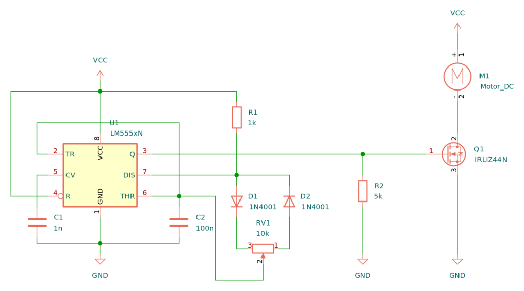
555 PWM Circuit Diagram
Note: For VCC, you can use anything from 5V to around 15V. What to choose will depend mostly on the size of the motor you are using. If it is small, you can control everything with 5V.
Components Needed
- 555 Timer IC
- IRLIZ44N MOSFET (or any other n-type MOSFET with a suitable gate threshold)
- 10 kΩ Potentiometer
- 1 kΩ Resistor
- 5 kΩ Resistor
- 1 nF Ceramic Capacitor
- 100 nF Ceramic Capacitor
- 1N4001 Diode
- Any DC motor
How the PWM 555 Circuit Works
The PWM 555 Circuit is known as an improved 555 oscillator. This is because it makes use of a couple of extra components to improve the output signal that the most common astable multivibrator circuit would give. It uses R1 and C2 to control the frequency of the signal. And you can modify the duty cycle with RV1.
With the duty cycle, you can control the average voltage in the output of the 555, which makes it a very functional analog controller for your projects. For example to control the speed of a motor or dim an LED.
In the example below, we’ll connect a motor.
How to Build the PWM 555 Circuit
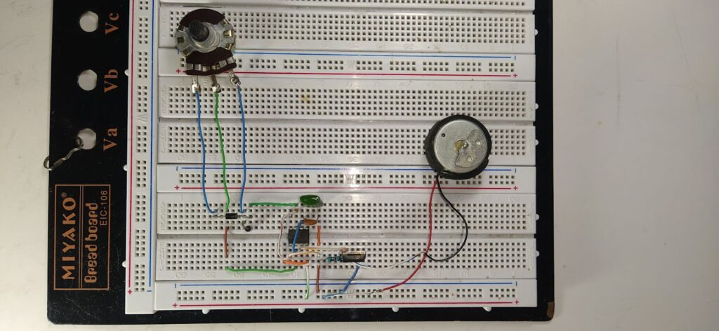
Here you can see the circuit already built:
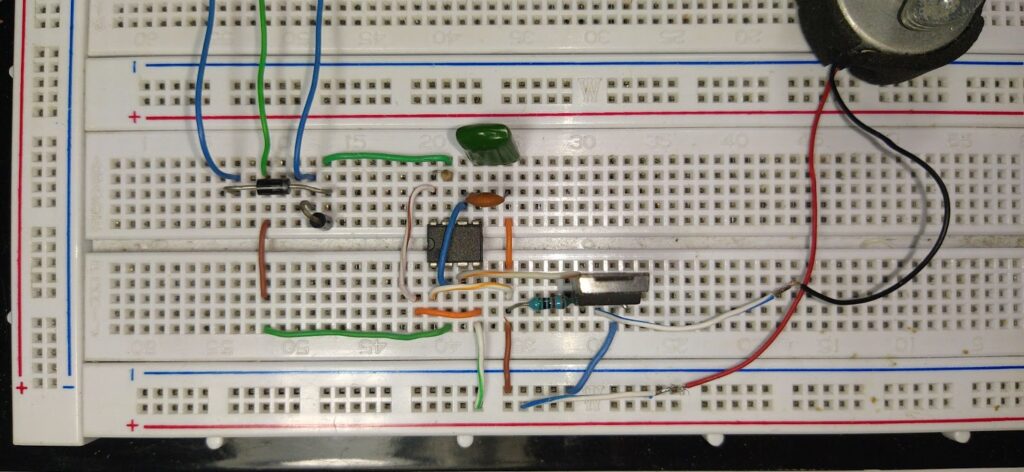
Here is a closer look, be aware of the placement of R1 and one of the diodes, which are placed in a way to not take too much space:
The Result
In this video you will be able to see the output of the PWM 555 Circuit, and how the duty cycle changes while changing the value of the potentiometer. It is also visible that the change in speed of the motor depends on the duty cycle.
Copyright Build Electronic Circuits
Wednesday, 22 June 2022
Organic bipolar transistor developed
Topological superconductors: Fertile ground for elusive Majorana ('angel') particle
Tuesday, 21 June 2022
Researchers harness the power of a new solid-state thermal technology
Friday, 17 June 2022
Next gen television and computer screens: Creating optically active polymers
Electrically conductive paints and other polymer alloys now produced easily
Thursday, 16 June 2022
Researchers change the game when it comes to activity tracking
Wednesday, 15 June 2022
New material paves the way for remote-controlled medication and electronic pills
Monday, 13 June 2022
Engineers build artificial intelligence chip
Researchers solve mystery surrounding dielectric properties of unique metal oxide
Friday, 10 June 2022
Researchers demonstrate 40-channel optical communication link
Wednesday, 8 June 2022
Scientists observe effects of heat in materials with atomic resolution
Tuesday, 7 June 2022
Yolk-shell nanocrystals with movable gold yolk: Next generation of photocatalysts
Monday, 6 June 2022
A novel all-optical switching method makes optical computing and communication systems more power-efficient
Friday, 3 June 2022
Scientists develop a 'fabric' that turns body movement into electricity
Controlling the waveform of ultrashort infrared pulses
Thursday, 2 June 2022
6G component provides speed, efficiency needed for next-gen network
'Fruitcake' structure observed in organic polymers
Researchers develop recyclable, healable electronics
Electronics often get thrown away after use because recycling them requires extensive work for little payoff. Researchers have now found a w...
-
Do you need a MOSFET gate resistor? What value should it be? And should it go before or after the pulldown resistor? If you’re a bit impati...
-
I was first introduced to logic gates when I was around 14 years old. I had heard that computers consisted of ones and zeroes. But I didn’t...
-
CMOS (Complementary Metal Oxide Semiconductor) The main advantage of CMOS over NMOS and BIPOLAR technology is the much smaller power dis...


