Wednesday, 31 March 2021
A new technique to synthesize superconducting materials
Tuesday, 30 March 2021
Scientists develop ultra-thin terahertz source
Discovery of a mechanism for making superconductors more resistant to magnetic fields
Monday, 29 March 2021
Deciphering the secrets of printed electronics
Saturday, 27 March 2021
Plasmon-coupled gold nanoparticles useful for thermal history sensing
Friday, 26 March 2021
Researchers harvest energy from radio waves to power wearable devices
From Arduino Prototype to Manufacturable Product
The Arduino is an ideal platform for proving your product concept. However, there is still a lot of engineering work required to turn it into a product that can be manufactured and sold.
The best way to progress from an Arduino prototype to a consumer product that is ready for sale is to use the same microcontroller as used in the Arduino. Although there may be higher performance and lower cost microcontrollers available, the simplest option is to just use the same microcontroller.
There are two key reasons why using the same microcontroller is the easiest option.
First, the firmware you’ve already developed is more easily ported over to the manufacturable version of your product.
Secondly, Arduino is open-source hardware so for the most part the circuit schematics can be simply copied.
Design the Schematic Circuit Diagram
The first step in migrating to a manufacturable product is to select the microcontroller. The simplest option is to use the same microcontroller as your Arduino model.
Selecting the microcontroller
The large majority of Arduino models are based on an Atmel AVR 8-bit microcontroller (see Table 1 below). The exceptions are the Arduino Due, Zero, MKR1000, and MKRZero all of which are based on 32-bit ARM Cortex-M architecture microcontrollers from Atmel (ARM Cortex-M is a very popular architecture implemented by many microcontroller manufacturers).
For this article I will be focusing solely on Atmel AVR 8-bit microcontrollers, and I will cover how to transition to an ARM Cortex-M microcontroller in a future article.
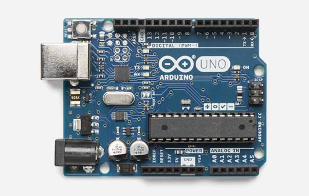
For this article we’ll be specifically dissecting the Arduino Uno which uses the Atmel ATmega328 microcontroller.
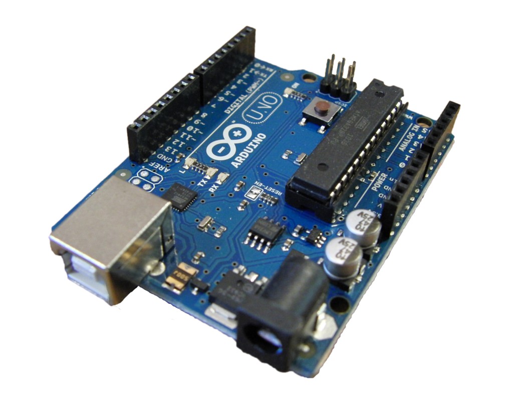 Figure 1 – Arduino Uno uses an ATmega328 microcontroller with 32kB of Flash memory
The ATmega328 used in the Uno is a through-hole DIP (Dual-Inline Package) version in a socket. Use of a socket allows the microcontroller to be easily swapped out if it becomes damaged. A socketed microcontroller may be a good idea for a development kit, but not for a production product.
First of all, a DIP package is going to be significantly larger than a SMT (Surface-Mount-Technology) package, especially with the added size of a socket. Secondly, your PCB assembly costs will be lower if you avoid through-hole packages entirely.
Finally, DIP packages tend to be more expensive since they are not generally used in high volume production. For example, the ATmega328 costs $1.66 @ 100 pieces in a DIP package, but only $1.18 for a SMT package.
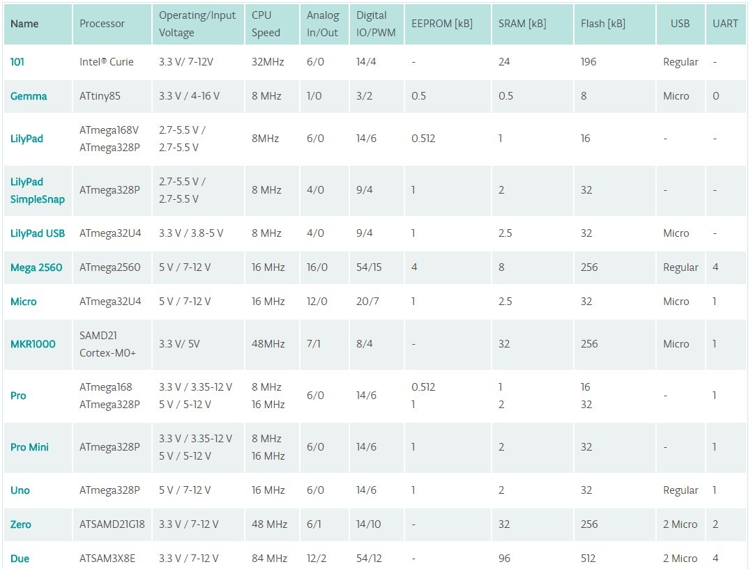 Table 1 – The microcontrollers used in the various models of Arduino.
There are numerous microcontrollers on the market that are more powerful and cheaper than the ATmega.
For example, there are 32-bit ARM Cortex-M microcontrollers available for about half the price of the ATmega328. Not only are they half the price but they include twice the memory and several times the processing power. In fact, there are 32-bit microcontrollers available for under $1!
However, using with the same microcontroller as your development kit will make the transition significantly less complicated. Both the hardware design and the software development will be simplified.
Schematic Review of Arduino Uno
One of the great things about the Arduino is that it’s an open-source platform. This means that you can easily view both the schematic and PCB layout for any of the Arduinos. Let’s start by looking at the schematic circuit for the Uno.
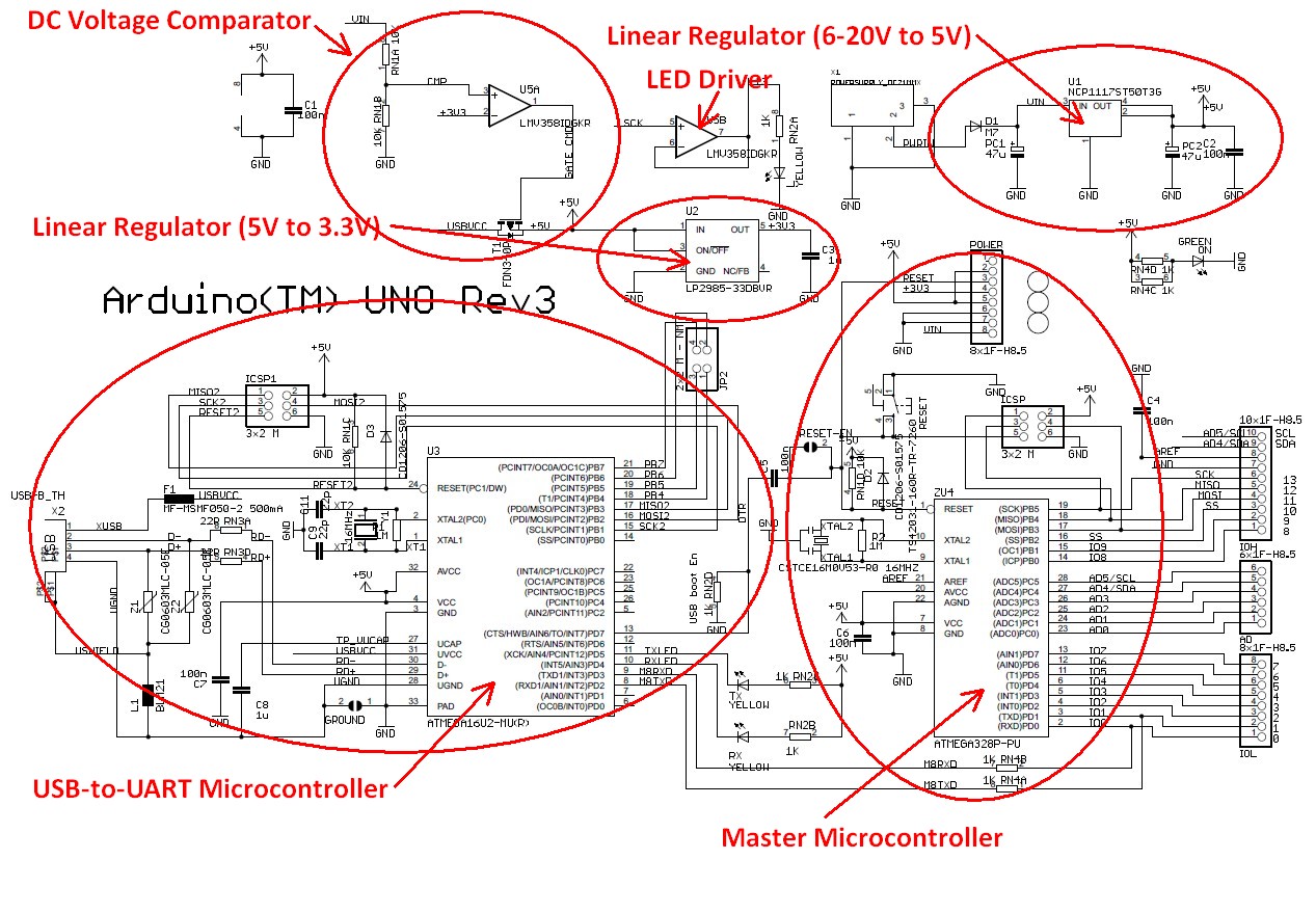 Figure 2 – Marked up schematic diagram for an Arduino Uno.
Looking at the schematic for the Arduino Uno you’ll see there are two primary integrated chips: U3 and U4. U4 is an ATmega328P microcontroller, and U3 is an ATmega16U2 microcontroller. Wait a second, why are there two microcontrollers?
The ATmega328P (U4) is the primary microcontroller. The second microcontroller (U3 – ATmega16U2) is solely there to provide a USB to UART conversion function since the ATmega328P doesn’t include a built-in USB port for programming. Older Arduinos instead used a specialized USB-to-UART chip from FTDI called the FT232RL.
By changing the FTDI chip to the ATmega16U2 it not only lowers the cost of the Arduino, but it also allows advanced users to use the USB port for other types of devices such as a keyboard or mouse. In general, a microcontroller based solution will provide more flexibility than a specialized solution like the FTDI chip.
As I will discuss later in regards to programming, with a custom microcontroller circuit you will no longer need a USB port in your design for programming purposes. So, if your product doesn’t require a USB communication for other purposes (USB charging is different), then you don’t need U3.
If you do require a USB port for your product then I would instead suggest you use a microcontroller that includes an embedded USB port, such as the ATmega32U4 microcontroller used on the Arduino Leonardo.
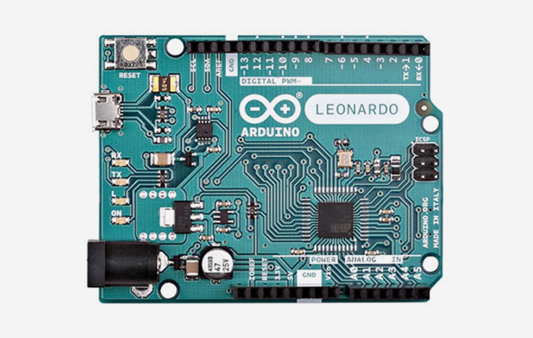 Figure 3 – Arduino Leonardo uses an ATmega32U4 microcontroller with a built-in USB port
That being said, the ATmega32U4 is quite pricey at around $3.47 @ 100 pieces. ST Microelectronics offers an ARM Cortex-M 32-bit microcontroller with USB functionality for only $1.92 @ 100 pieces.
Microcontroller Support Circuitry
Each of the two microcontroller circuits in the Uno consists of a crystal oscillator running at 16 MHz, various GPIO (General Purpose Input/Output) signals, multiple serial interfaces including one for programming, a power supply, and lots of decoupling capacitors.
U5 is a dual op-amp (operational amplifier) called the LMV358IDGKR from Texas Instruments. One of the two op-amps (U5A) is operated as a comparator since it has no feedback. This comparator is used to determine if the Arduino is being powered by the DC input or via the USB port.
If the 6-20V DC input voltage is present then the 5V supply is generated by an on-board linear regulator (as I discuss in detail shortly). On the other hand, if the 6-20V DC input is not present then the 5V supply voltage comes from the USB port.
So, if there is a 6-20V DC input voltage supplied then the positive input of the U5A comparator is higher than the negative input (3.3VDC). In this case the output of the comparator will be high, and PMOS transistor T1 will be turned off. This disconnects the internal 5V signal from the USB supply voltage.
If the 6-20V DC input is not present then the output of U5A will be low which turns on T1, thus the internal 5V supply comes from the USB port.
The other op-amp in U5 (U5B) is connected in a configuration known as a unity-gain feedback amplifier. This is a fancy way of saying that it has a gain of 1 which means it acts as a simple buffer.
Whatever voltage you put on the input of U5B is what you get on the output. The purpose is that now the output is able to drive a much larger load. In this case, this buffer is there simply to flash an LED whenever the serial programming clock (SCK) signal is present.
Power Circuit
The power circuit for the Uno is based on an NCP1117 linear regulator from ON Semiconductor. This regulator generates a 5V DC voltage from the 6-20V DC input voltage and can source up to 1A of current.
The use of a linear regulator in this situation is fine for some products, but not if your product is powered from a battery, or consumes large amounts of current. A linear regulator such as the NCP1117 is extremely inefficient when the input voltage is significantly higher than the output voltage. Being inefficient means it wastes a lot of the power by dissipating heat.
For example, on the Uno the input voltage can be as high as 20V, and the output voltage is only 5V. This means the input-output differential voltage is 15V. If you pull the maximum current of 1A from this regulator the power dissipated by the linear regulator would be (Vin – Vout) * Iout = (20V – 5V) * 1A = 15W!
If the NCP1117 didn’t have an internal thermal shutdown feature, it would literally cook while trying to dissipate this much power. Regardless, you will waste all of this power as heat.
If you need to step-down a high voltage to a significantly lower voltage then a switching regulator is a much better choice. I won’t get into the details of switching regulators in this article, but they are many times more efficient than linear regulators. However, switching regulators are also considerably more complex than linear regulators.
On the Uno a LP2985 linear regulator from Texas Instruments is used to create a 3.3V voltage. The LP2985 is rated for 150mA of load current. This type of linear regulator is also called a Low-Drop-Out (LDO) regulator because it requires very little differential voltage from the input to the output.
Older, non-LDO linear regulators required the input voltage to be a few volts above the output voltage. However, from a power dissipation standpoint it’s best to operate a linear regulator with an input voltage close to the output voltage.
The 3.3V voltage is fed into a comparator (U5A) that is used to switch to USB power, if available, when no power supply is plugged in.
The LP2985 doesn’t dissipate that much power so a linear regulator is a good choice for this regulator. This is because the input-output voltage differential is only 5V – 3.3V = 1.7V, and the maximum current is only 150mA.
A very common strategy is to use a switching step-down regulator (also called a buck regulator) followed by a linear regulator. In addition to the increased complexity, the other downside of a switching regulator is it provides a “noisy” output voltage. This is fine for many applications. However, if you require a cleaner supply voltage it’s best to add a linear regulator to clean up the output voltage from the switching regulator.
What About Any Shields?
You are probably also using some shields that will also need to be converted to a custom schematic. If the shield is providing wireless functionality then in most cases you are better off using a surface-mounted module which solders directly on to your PCB.
There are two reasons for using a module for wireless functions. First, the PCB for a wireless radio can be quite complex to lay out correctly. Secondly, the use of pre-certified modules will simplify the process of getting your product certified.
Other functions, such as sensors and motor controllers, are best accomplished with a custom circuit design.
In future articles I will discuss in detail how to migrate various Arduino shields to a production circuit.
Design the Printed Circuit Board (PCB)
Now that the schematic design is completed, it’s time to turn it into Printed Circuit Board (PCB). A schematic is simply an abstract technical diagram, but a PCB is how you turn your design into a real-world product.
Since the Arduino is open-source hardware the PCB layout design is available for reference. However, you will almost surely need to redesign the PCB for your specific product size requirements.
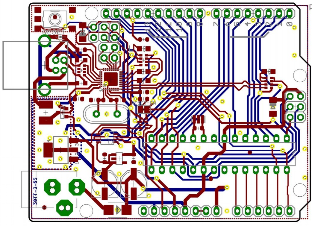 Figure 4 – PCB layout for the Arduino Uno
A microcontroller circuit with a clock speed of only 16 MHz, without wireless functionality, is a fairly simple PCB layout to design (assuming you know how to do PCB layout). Things become much more complicated once speeds approach hundreds of MHz, or especially GHz.
Be cautious about two things when laying out an Arduino Uno equivalent microcontroller circuit. First, the crystal and it’s two load capacitors need to be laid out correctly and placed as close as possible to the microcontroller pins.
Secondly, carefully lay out any decoupling capacitors so they are as close as possible to the pin that is being decoupled. Be sure to always review the microcontroller datasheet for PCB layout guidelines.
To learn how to design a custom PCB board be sure to check out this tutorial.
Order PCB Prototypes
Once the PCB layout is completed it’s now time to order the boards. However, before ordering any PCB prototypes you should really get an independent design review of the schematic and PCB layout.
Regardless of the designer’s experience level, an independent design review reduces the likelihood that mistakes will make their way into your prototype. I always get other engineers to review my own designs and so should you.
In some cases you may have two different vendors make your boards. One vendor will produce the blank PCB’s, and then another supplier will solder the components onto the board. In other cases, a single vendor will perform both steps.
For your first prototype version I suggest ordering only 3-10 boards. This is because the first version will likely have various bugs that will need to be fixed. In most cases it’s a waste of money to order a large quantity on the first version.
Once you’ve tested and debugged the first version, then increase the quantity for the second order.
Develop the Firmware/Software
One aspect of an Arduino that is different than your own, custom microcontroller circuit is how the programming is done. An Arduino is programmed via a USB port. This allows it to be programmed from any computer without the need for special hardware.
On the other hand, a custom microcontroller is usually programmed via a serial port protocol such as SPI, SWD, UART, or JTAG. In order to program a microcontroller using one of these serial programming protocols you’ll need a special piece of hardware called an In-Circuit Serial Programmer (ICSP) or In-System Programmer (ISP).
You’ll also sometimes see “programmer” substituted with “debugger” since this hardware device also allows you to see the inner workings of the microcontroller for debugging purposes.
These devices are called In-Circuit or In-System programmers/debuggers because the microcontroller can be programmed directly in the system without any need to remove the microcontroller.
The old method of programming required the microcontroller be removed from the circuit for programming, then re-inserted back into the circuit. This is a very inefficient method of programming a microcontroller during development.
The AVRISP from Atmel is an example of an in-system programmer for the Atmel AVR line of microcontrollers.
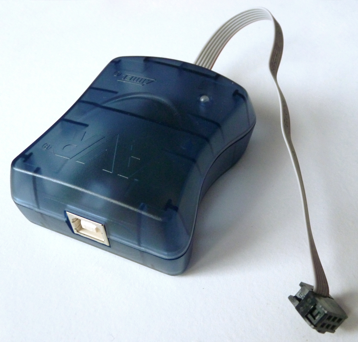 Figure 5 – The Atmel AVRISP mkII In-System Programmer (ISP)
This special programming hardware isn’t required for an Arduino since it is essentially already embedded in the Arduino. As already discussed, the Arduino Uno incorporates a USB-to-UART converter to allow programming via a standard USB port.
Once you have the necessary programming hardware it’s time to port over your Arduino sketch to native firmware code.
Just as with a custom microcontroller, an Arduino is programmed using the C language. However, programming is greatly simplified on the Arduino since it already contains a huge library of various functions.
For example, to setup a GPIO pin as an output on an Arduino, and then output a low logic level, you would use the following two functions:
pinMode(PinNumber, OUTPUT);
digitalWrite(PinNumber, LOW);
When you execute these two functions, the real work is performed by the library code behind these functions. For a custom microcontroller circuit the library code for these two functions must also be ported over to your microcontroller code (this will covered in more detail in a future article).
Finally, remember that you don’t have to use the exact same microcontroller as your Arduino to simplify programming. Selecting a microcontroller from the same line of microcontrollers will still significantly simplify the transition from Arduino to production.
For example, porting your Arduino code over to any 8-bit AVR microcontroller will be considerably less complex than porting it over to a 32-bit microcontroller.
Test, Debug, and Repeat
It doesn’t really matter how good you are at designing circuits. Unless your product is exceptionally simple, you are almost guaranteed to make at least one or two mistakes in your design.
Be sure to account for this fact in your planning. That being said, accurately planning for debugging is extremely challenging since you are inherently dealing with unknown and unexpected problems.
Conclusion
In this article we’ve looked at the simplest example of migrating from an Arduino prototype to a manufacturable product. However, the simplest method is rarely the best method.
The Atmel AVR microcontrollers used in most Arduino kits are a great choice for learning about microcontrollers, but they are not necessarily the best choice in a production product.
There are many other microcontrollers available that will give you significantly more bang for your buck. In future articles I will discuss how to migrate from a 8-bit Arduino to a more powerful, and typically lower cost, 32-bit microcontroller.
If you’d like to learn more about how to develop and sell your own electronic hardware product then be sure to download my free guide: Ultimate Guide: How to Develop and Sell Your New Electronic Hardware Product.
This article was written by John Teel who is the founder of Predictable Designs, a company which helps entrepreneurs bring new electronic products to market. John was formerly a design engineer for Texas Instruments where he created electronic designs now used in millions of products. He also developed his own hardware product that sold in over 500 retail locations in three countries.
Copyright Build Electronic Circuits
Thursday, 25 March 2021
Technology uses 'single' approach to develop electronics, acoustics
Wednesday, 24 March 2021
Optical fiber could boost power of superconducting quantum computers
Tuesday, 23 March 2021
Scientists observe complex tunable magnetism in a topological material
Sunday, 21 March 2021
A promising breakthrough for a better design of electronic materials
Artificial neuron device could shrink energy use and size of neural network hardware
Wednesday, 17 March 2021
Magnetism meets topology on a superconductor's surface
How Transistors Work – A Simple Explanation
How transistors work is something everyone interested in electronics should learn. And it’s easy. You can turn a transistor on and off with a voltage.
And I’ll show you how both an NPN and a MOSFET transistor works.
The transistor is like an electronic switch. It can turn a current on and off. A simple way you can think of it is to look at the transistor as a relay without any moving parts. A transistor is similar to a relay in the sense that you can use it to turn something ON and OFF.
But a transistor can also be turned partly on, which is useful for building amplifiers.
How an NPN Transistor Works
The NPN transistor has three legs:
- Base (b)
- Collector (c)
- Emitter (e)
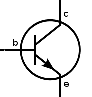
A current flowing from the base to the emitter “opens” the flow of current from the collector to the emitter.

How to get current flowing from base to the emitter?
That’s actually pretty easy. To get current flowing from base to emitter, you need a voltage of about 0.7V between the base and the emitter.
So when you apply 0.7V from base to emitter you will turn the transistor ON and allow a current to flow from collector to emitter.
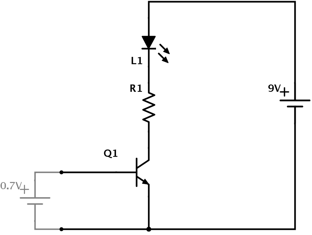
In the example above you can see how transistors work. A 9V battery is connected to an LED and a resistor. But they are connected through the transistor. And no current flows through the transistor until it’s turned ON.
To turn the transistor ON you need to apply 0.7V from base to emitter of the transistor. Imagine you have a small 0.7V battery. When you connect the 0.7V battery from base to emitter, the transistor turns ON.
This allows current to flow from the collector to the emitter. And thereby turning the LED ON!
Check out the video explanation I made on the transistor a few years back (forgive the old-school quality):
Practical Example: Basic NPN Transistor Circuit
Since most of us don’t have a 0.7V battery, how do we turn on the transistor?
Easy =) Just add a resistor in series with the base and apply a voltage. Just like you would do with an LED to make sure it doesn’t blow up.
This is because the base-to-emitter part of a transistor works like a diode. A diode has a forward voltage that it “grabs” from the available voltage. And the rest of the voltage drops across the resistor.
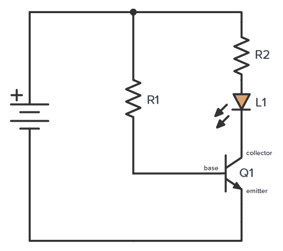
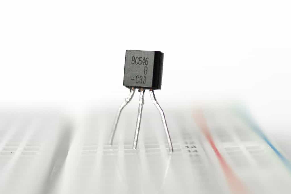
In the above circuit, R1 limits the current to the base. And R2 limits the current to the LED. If you want to build it, you can try 10 kΩ for R1 and 1 kΩ for R1. Any NPN transistor will work, for example, BC547 or 2N3904.
The above circuit isn’t very useful. But you can at least test turning the transistor ON and OFF by connecting and disconnecting R1.
The NPN transistor is the most common of the Bipolar Junction Transistors (BJT). But there is another one called a PNP transistor that works in the opposite direction.
If you want a more useful example, have a look at this light sensor circuit.
How a MOSFET Transistor Works
The MOSFET transistor is another very common type of transistor. It also has three pins:
- Gate (G)
- Source (S)
- Drain (D)

It works similar to the BJT transistors, but with one difference:
In the BJT transistor, the amount of current from base to emitter decides how much current can flow from collector to emitter.
In the MOSFET transistor, it’s the voltage between gate and source that decides how much current it lets through from drain to source.
More on the Transistor
The transistor works because of something called a semiconducting material. A current flowing from the base to the emitter “opens” the flow of current from the collector to the emitter.
The transistor is also what makes amplifiers work. Instead of having just two states (on or off) it can also be anywhere in between “fully on” and “fully off”.
A small “control current” can then control how big a portion of a bigger “main current” that is going to flow through it. Thereby, the transistor can amplify a signal.
If you want to learn more about using the transistor as an amplifier, electronics-lab.com has some nice tutorials that go through the three basic BJT amplifier setups.
We use transistors in almost all electronics and it’s probably the most important component in electronics.
Do you understand how transistors work? Go check out the H-Bridge circuit and see if you can understand it.
Copyright Build Electronic Circuits
Tuesday, 16 March 2021
Catching electrons in action in an antiferromagnetic nanowire
Friday, 12 March 2021
New perovskite LED emits a circularly polarized glow
Unique Ag-hydrogel composite for soft bioelectronics created
Thursday, 11 March 2021
Scientists stabilize atomically thin boron for practical use
New analysis of 2D perovskites could shape the future of solar cells and LEDs
Tuesday, 9 March 2021
The Pull-Up Resistor: How It Works and Choosing a Value
The pull-up resistor is very common and you’ll see it in digital circuits all the time. It’s just a resistor connected from an input up to VDD, the positive supply of the circuit.
For example on digital inputs on an Arduino. Or the input of digital chips such as the 4000-series IC.
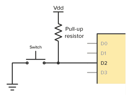
Pull-up resistors are used to make sure you have a HIGH state on the input pin when the button is not pushed. Without one, your input will be floating, and you risk that the input randomly changes between HIGH and LOW as it picks up noise in the air.
How To Choose a Pull-Up Resistor Value
Rule 1: The value can’t be too high.
The higher the pull-up value, the lower the voltage on the input becomes. It’s important that the voltage is high enough for the chip to see it as a HIGH, or logical 1, input.
For example, if you use a CD4017 with a power supply of 10V, it requires a minimum of 7V on the input for it to be seen as HIGH.
Rule 2: But it can’t be too small either.
If you for example choose 100 Ω, the problem is that you get a lot of current flowing through it when the button is pushed.
With a 9V power supply, you get 9V across 100 Ω, which is 90 mA. It’s an unnecessary waste of power, but it also means the resistor needs to withstand 0.81W. Most resistors can handle only up to 0.25W.
Rule of thumb
The rule of thumb when choosing a pull-up resistor is to choose a resistance value that is at least 10 times smaller than the input impedance (or the internal resistance) of the pin.
Often, a pull-up value of 10 kΩ will do the trick. But if you want to understand how it works, keep reading.
How Do Pull-Up Resistors Work?
You can think of the input pin of an integrated circuit (IC) as having a resistor connected to ground. This is called the input impedance:
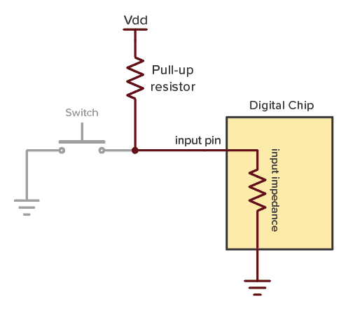
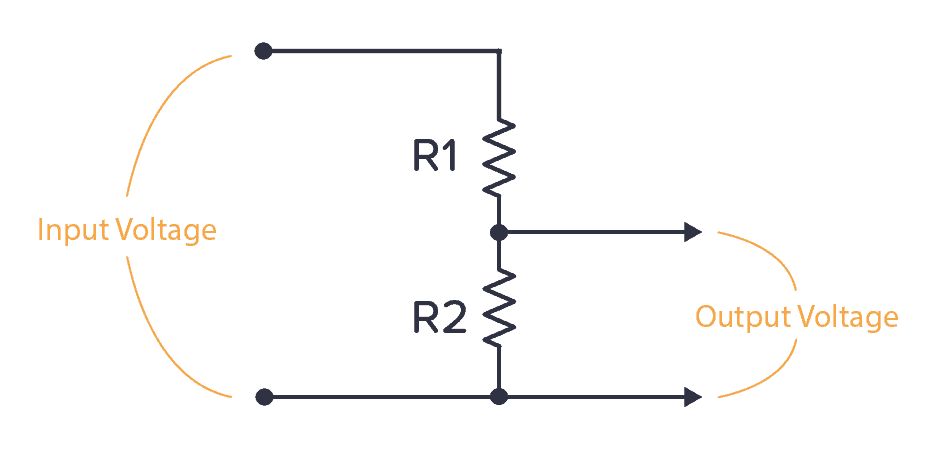
These two resistors make up a voltage divider. If you look at the standard voltage divider circuit, you can see that the pull-up resistor is R1 and the input impedance is R2:
You can use the voltage divider formula to find the voltage on the input pin when the button is not pushed:

Below, I’ve renamed the components of the formula to fit the pull-up example. The input voltage is VDD from our pull-up example. And the output voltage is the voltage on the input pin. So the formula becomes:

Example Calculation
Let’s say your chip has an input impedance of 1MΩ (100kΩ to 1MΩ is normal for many chips). If your power supply is 9V and you choose a pull-up resistor value of 10 kΩ, what’s the voltage you get on the input pin?

You get 8.9V on the input pin, which is more than enough to act as a HIGH input.
In general, if you stick to the rule of thumb of using a pull-up resistor that is no more than ten times lower than the input impedance, you’ll make sure you always have a minimum of 90% of the VDD voltage on the input pin.
How To Find the Input Impedance of an IC
You can easily measure the input impedance of a chip. Impedance is actually a term for resistance that can change depending on frequency. But for this pull-up case, we only deal with DC currents.
Connect a pull-up resistor of for example 10 kΩ to the input of the chip, and measure the voltage on the input.
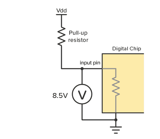
Let’s say you got 8.5V when you measured.
Use this to find the current flowing through the resistor by using Ohm’s law. The voltage drop across the resistor is 9V – 8.5V = 0.5V, so you get:

There is 0.05 mA flowing through the resistor, and thereby also through the input pin down to ground. Again, use Ohm’s law to find the resistance of something with a voltage drop of 8.5 V and a current of 0.05 mA:

The input impedance is 170 kΩ. That means a pull-up resistor for this input should be no more than 17 kΩ.
Questions?
What questions do you have about the pull-up resistor? Let me know in the comments field below!
Copyright Build Electronic Circuits
Monday, 8 March 2021
Lights on for silicon photonics
Reduced heat leakage improves wearable health device
Friday, 5 March 2021
Life's rich pattern: Researchers use sound to shape the future of printing
The Voltage Divider: How This Simple Formula Works
A voltage divider is a circuit that divides a voltage between two resistors. You’ll see it in both simple and advanced circuits all the time.
It’s extremely useful to know!
If you know how it works, it’s much easier to see how circuits work. And it will let you calculate voltages at many different points in a circuit – which is often needed to understand it.
Voltage Divider Formula
I have to admit that I have made more use of my practical experience with building circuits than I have from the electronics theory I learned at the university. But this formula is one of the few electronics formulas I actually use on a regular basis.
It’s for finding the output voltage when you have two resistors connected like this:
The formula for calculating the output voltage is:

I recommend you memorize this formula. It will come in handy often.
Where Do You Find The Voltage Divider?
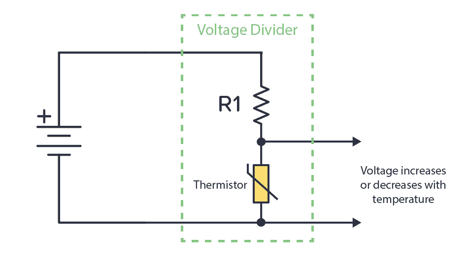
One example of the voltage divider circuit is for analog sensors. For example, the thermistor is a temperature sensor. It changes its resistance based on the temperature. If you connect it with a known resistor value in a voltage divider setup, you’ll get a voltage that depends on temperature:
Or you can combine a known resistor with a photoresistor. The photoresistor changes resistance based on the amount of light it detects. This way, you have a circuit that increases or decreases the voltage based on light.
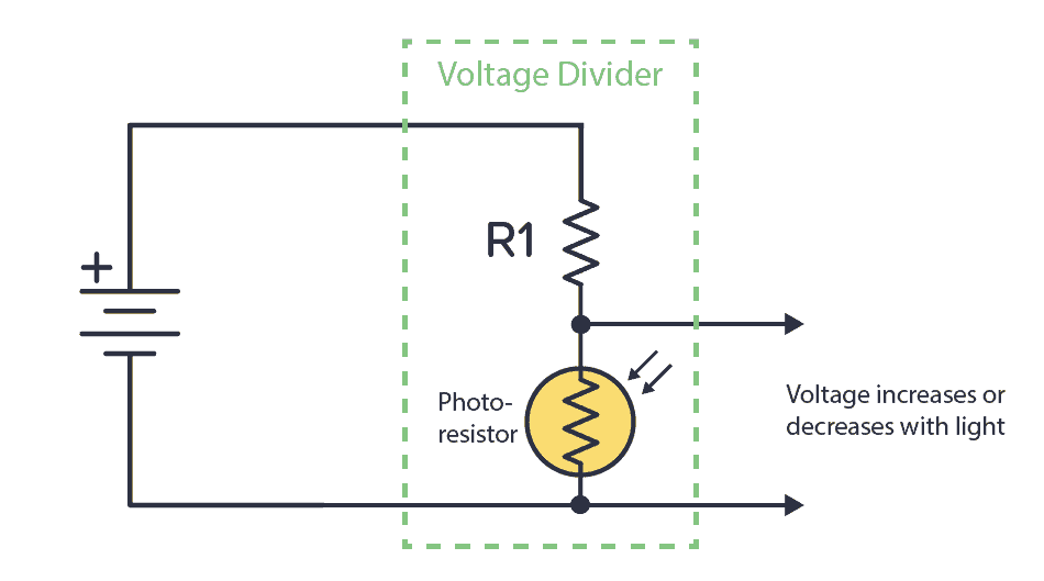
You can connect the output of any of these circuits into a comparator to check it’s above or below a certain voltage. Then do something based on that. For example, if the temperature is above 40 degrees, turn on a fan.
Or connect into an analog pin of an Arduino or a microcontroller and do cool stuff with it. Maybe turn on a light if the photocell indicates that it’s dark?
Calculation Example: Different resistor values
Let’s say we have the following values:

By using the formula above we get

Calculation Example: Equal resistor values
Now, let’s say R1 and R2 has the same value.

By using the formula above we get

This means that when the two resistors have the same value, the output is always half the input.
Questions?
What are your questions around the voltage divider? Let me know in the comment section below.
Copyright Build Electronic Circuits
Thursday, 4 March 2021
'Egg carton' quantum dot array could lead to ultralow power devices
Tuesday, 2 March 2021
New strategy for efficient OLED active matrix displays
-
CMOS (Complementary Metal Oxide Semiconductor) The main advantage of CMOS over NMOS and BIPOLAR technology is the much smaller power dis...
-
I was first introduced to logic gates when I was around 14 years old. I had heard that computers consisted of ones and zeroes. But I didn’t...
-
Do you need a MOSFET gate resistor? What value should it be? And should it go before or after the pulldown resistor? If you’re a bit impati...


