Monday, 30 January 2023
Superconductivity switches on and off in 'magic-angle' graphene
Powering wearable technology with MXene textile supercapacitor 'patch'
Saturday, 28 January 2023
Transistors repurposed as microchip 'clock' address supply chain weakness
Wednesday, 25 January 2023
The T Flip-Flop (Quickstart Tutorial)
The T Flip-Flop is a flip-flop that can toggle its output. Toggling means switching its output to its opposite; 1 becomes 0, and 0 becomes 1. This type of flip-flop is often used in counters and frequency dividers.
In this quickstart tutorial, you will learn how it works, its truth table, and how to build one.
What is a T Flip-Flop?
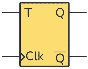
Flip-flops are components commonly used to store a digital value on their output. They have a Clock (Clk) input that decides when to update their output.
The T Flip-Flop is a single-input flip-flop that either holds or toggles its output value.
Toggling, which is the reason for the “T” in the name, means changing between two states. If the output is 1, toggling will change the output to 0. If the output is 0, toggling will change the output to 1.
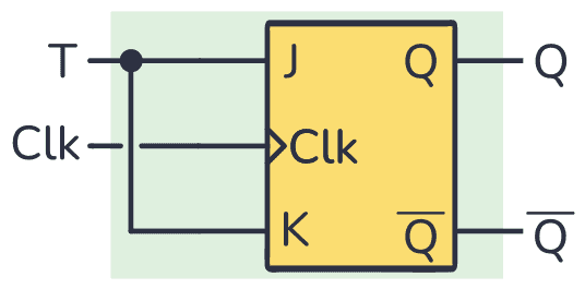
You can build a T Flip-Flop from other flip-flops, for example by using the JK flip-flop and connecting the J and K inputs as follows:
Truth table
In general, you can trigger T Flip-Flops with a falling edge signal, which is the change from a digital state of 0 to 1 ↓, or with a rising edge signal, a change from 1 to 0 ↑. The following truth table corresponds to a flip-flop that triggers on the rising edge:
| Clk | T | Previous Q | Next Q | Description |
|---|---|---|---|---|
| 0 or 1 | X | Q | Q | No rising edge no change |
| 0→1 (↑) | 0 | Q | Q | Memory (no change) |
| 0→1 (↑) | 1 | 0 | 1 | Toggle |
| 0→1 (↑) | 1 | 1 | 0 | Toggle |
You can see that if there is no rising edge in the Clk input, no matter what you put into the T input, the Q output will remain unchanged.
Something like the previous case happens when you have a 0 in the T input. Even if the flip-flop is triggered, if you have either 0 or 1 in the Q output it will stay that way.
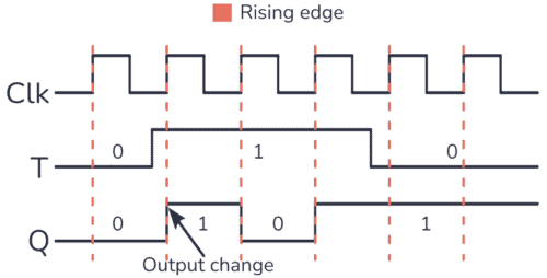
To get the Toggling behavior you have to place a 1 in the T input. What you will observe is a change from 0 to 1 or from 1 to 0 every time the flip-flop is triggered. You can see this behavior in the timing diagram below:
Building a T Flip-Flop Circuit
You can build a T Flip-Flop just by shorting the J and K inputs of a JK flip-flop. However, some websites out there suggest you build the circuit like below. But this is an incomplete circuit that will not work properly:
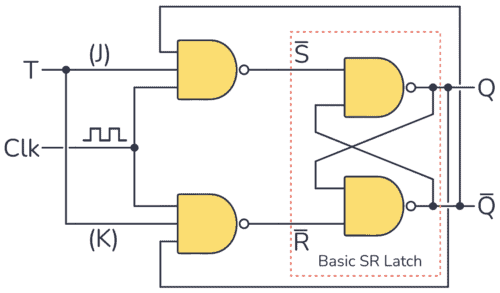
On paper, it seems to work. But what most websites that publish this circuit fail to mention is that you need a very short clock pulse for it to work.
Your clock pulse needs to go high, then low again before the output (Q) changes state. Otherwise, the Q output will toggle quickly between 1 and 0 during the entire positive pulse duration. You can see this behavior in the following timing diagram:
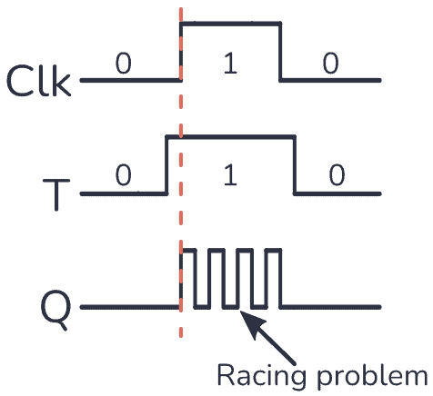
This is a problem called Racing. But it’s easily solved by using an edge-triggered JK Flip-Flop instead.
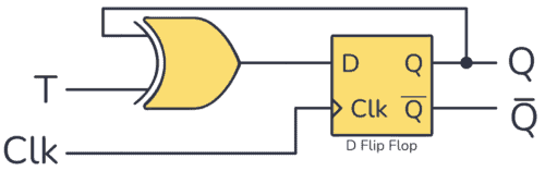
You can also build a fully functional T Flip-Flop by using a D Flip-Flop combined with an XOR gate, like this:
Example Circuit: Toggling an LED
As a practical example, you can toggle a light-emitting diode (LED) using just one push button, the T Flip-Flop, and some resistors. Check out the circuit below:
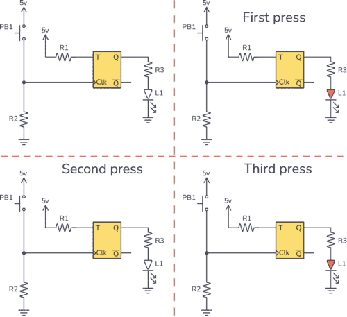
You can see how the T input is connected to 5V, which means logic 1. So every time you trigger the T Flip-Flop, the Q output will toggle its state.
The Clk input uses a pulldown resistor configuration, which means that the Clk input is 0 whenever the button is not pushed. When you press the button PB1, the Clk input will go from 0 to 1 (rising edge signal).
So every time PB1 is pushed, the LED connected to the output Q turns on or off.
To assemble the above circuit you need:
- 1x T Flip-Flop circuit (ex by combining a CD4013 and a CD4030)
- 2x 10 kΩ resistor (R1 and R2)
- 1x 330 Ω resistor (R3)
- 1x Pushbutton
- 1x LED
Questions?
Do you have any questions about this component? Let me know in the comments below and I’ll get back to you as soon as possible.
Copyright Build Electronic Circuits
Tuesday, 24 January 2023
Spin transport measured through molecular films now long enough to develop spintronic devices
Friday, 20 January 2023
Two technical breakthroughs make high-quality 2D materials possible
Thursday, 19 January 2023
Polysulfates could find wide use in high-performance electronics components
Wednesday, 18 January 2023
Microelectronics give researchers a remote control for biological robots
Engineers grow 'perfect' atom-thin materials on industrial silicon wafers
How To Use A Breadboard – The Beginner’s Guide
A breadboard is a simple and useful tool for connecting a circuit. It’s really useful for beginners as you can easily experiment and test out circuits without soldering. But it’s also useful for more experienced people since you can prototype an idea, or parts of a circuit, quickly.
I often use breadboards in my work.
Want a quick introduction to the breadboard? Check out my short video below (2:30) or continue reading.
How To Use A Breadboard
The breadboard has internal connections between its holes. Some vertical connections and some horizontal connections.
Normally, you use the columns on the sides to connect your power supply. And you use the rows in the middle to connect your components.
Power Supply Columns
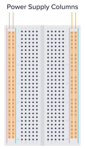
It’s common to use the columns on the left and right for connecting the power supply. These columns are connected vertically. So, if you connect 5 volts to the top hole of one of the side columns, you will have 5 volts in all the holes of this column.
Use the columns marked with a red line for plus, and the column marked with a blue line for minus.
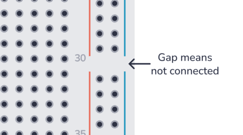
Note: Some larger breadboards are split into two so that the upper half is disconnected from the lower half. This is indicated by the vertical blue and red lines being split in two.
Component Area
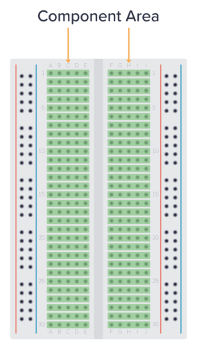
In the middle of the board, you’ll find the component area. This is where you normally connect your components. Here, the holes are connected horizontally, in rows. And the left side is separated from the right side.
This means that the pins of your component must be on different rows, or on different sides of the board. Below you can see two ways to connect a resistor:
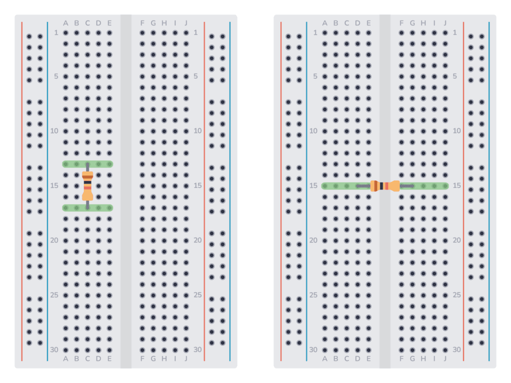
To connect something to either pin of the resistor, you need to connect it to one of the rows marked in green.
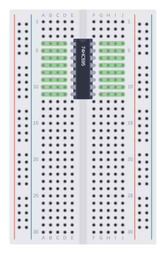
If you want to connect a chip, you need to connect it across the gap in the middle. Then, to connect something to one of the pins, use the holes marked in green:
Example Breadboard Circuit
Here’s a simple circuit diagram of a resistor and LED connected to a 9V battery:
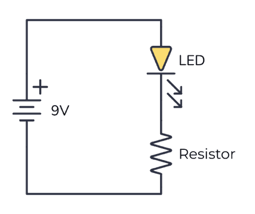
To connect this circuit to a breadboard, first connect the resistor, making sure the pins are on different rows. Then connect the LED, making sure its negative leg is connected to the same row as the upper leg of the resistor.
This is such a simple circuit, that it’s not necessary to use the power supply columns. You can connect the battery directly to the component area. Here’s the complete circuit with a resistor and LED connected to a 9V battery on a breadboard:
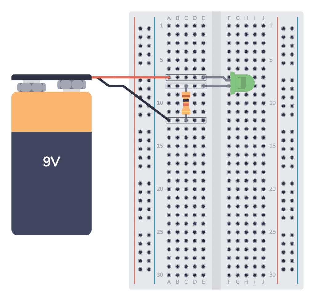
In the circuit above, I used three rows:
- The upper row connects the plus of the battery to the positive leg of the LED.
- The middle row connected the negative leg of the LED to the upper leg of the resistor.
- The lower row connects the lower leg of the resistor to the minus of the battery.
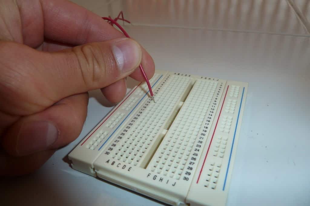
Best Wire Thickness to Use on a Breadboard
Not all wires work well with breadboards. In my experience, the best wires to use are 22 or 23 AWG single-strand wires. Single-strand means the wire has one solid core inside (as opposed to lots of tiny wires wrapped together).
AWG stands for American Wire Gauge. And 22 AWG means a diameter of 0.65 mm. And 23 AWG is 0.57 mm.
For other basic components, buy them with a leg thickness of 0.5-0.7 mm for the best fit. Most through-hole components will fit in a breadboard, but I’ve come across components with legs that are too thick to fit, or too thin to give a good connection.
What Can You Build With A Breadboard?
Breadboards are often used to build a prototype or to test a circuit. Or a part of a circuit that you are unsure about.
For example, let’s say you wanted to build a microcontroller circuit that controlled relays with the output pins from the microcontroller. Then you would want a little driver on the output. If you are unsure about this driver circuit, you could throw it together on a breadboard quickly to make sure it works before you put it into your final design.
Or if you are learning about circuits you will come across a lot of little circuits that you want to test. Connecting these on a breadboard can be really useful.
But you can also use breadboards to build complicated circuits, as long as you have enough space and are comfortable with lots of wire connections.
Check out how to build a blinking LED circuit on a breadboard.
Copyright Build Electronic Circuits
Tuesday, 17 January 2023
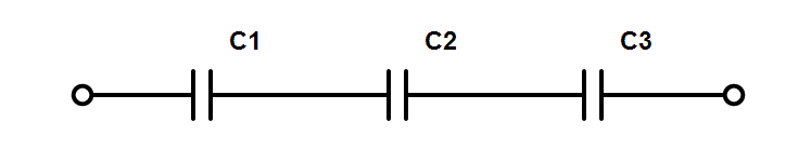
Capacitors in Series
When you connect capacitors in series, you connect them one after the other. And you can think of them as one capacitor with a value that is always lower than the lowest value.
For example, if you connect three 300 µF in series, the combined capacitance becomes 100 µF. This can be useful for getting a specific capacitor value that you don’t currently have in your component selection.
How to Calculate the Value of Capacitors in Series
Calculating capacitors in series is done in the same way as you calculate resistors in parallel.
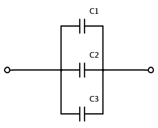
This is the formula for calculating the total capacitance of three capacitors connected in series:

To find CTOTAL you need to flip both sides, and you’ll end up with this:

This is a little bit less intuitive than calculating capacitors in parallel. But if you use equal values for all the capacitors, the result becomes the value of one, divided by the number of capacitors. So if you for example place three 330 nF capacitors in series, you’ll end up with 330 nF / 3 = 110 nF.
You can place as many capacitors in series as you want. Just add more C’s to the formula above.
The fact that the capacitance becomes lower as you add more capacitors makes sense when you think about how capacitors work: A capacitor is basically just two metallic plates, placed close to each other, with an insulating material in between.
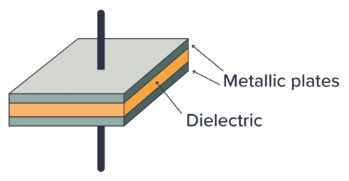
The larger the space between the plates, the lower the capacitance. So when you place two (or more) capacitors in series, it’s more or less the same as having more space between the first and last plates.
Voltage Across Capacitors in Series
The voltage across capacitors connected in series will be divided between the individual capacitors. If you know that there is 5V across all the capacitors, it means that the sum of the voltages across each individual capacitor will be 5V.
But it’s hard to say what the value for each capacitor is since it depends on its capacitance, internal resistance, and how much it’s been charged.
This isn’t specific to capacitors. Any series connection of components will have the total voltage divided among the components. I recommend reading up on the basics of voltage and current if you’re not comfortable with this concept.
Why Use Capacitors Connected in Series?
The most common reason for connecting capacitors in series among hobbyists is simply that you don’t have the exact capacitor value needed. By connecting several capacitors in series, you can achieve other values.
Let’s say you have built the blinking light circuit, and find that the LED is blinking too slowly. You used 100μF for C1 in the schematic below, and that’s the only value you have in your component kit.
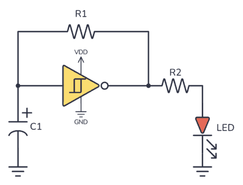
By adding another 100 µF in series with C1, the total resistance becomes 50 µF. And your light blinks with twice the speed instead.
Normally, you never need capacitors connected in series unless you need to achieve a capacitance value that you don’t have at hand.
Summary
The formula for calculating the value of capacitors in series becomes easier if you use the same value for all capacitors. Then the result becomes the value of one, divided by the number of capacitors. Ex five 1000 µF capacitors in series become 1000 µF / 5 = 200 µF.
You usually only place capacitors in series if you need a specific value that you don’t have available.
Copyright Build Electronic Circuits
Capacitors in Parallel
When you connect capacitors in parallel, you connect them alongside each other. And you can think of them as one capacitor with a higher value. You’ll find that value by adding the values of each capacitor.
For example, if you connect three 1000 µF in parallel, the combined capacitance becomes 3000 µF. This can be useful for getting a specific capacitor value that you don’t currently have in your component selection.
How to Calculate the Value of Capacitors in Parallel
Calculating capacitors in parallel is very easy. You just add the values from each capacitor.

So if you place a 470 nF capacitor and a 330 nF capacitor in parallel, you’ll end up with 800 nF. You can place as many capacitors in parallel as you want.
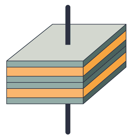
The formula for calculating capacitors in parallel makes sense when you think about how capacitors work: A capacitor is basically just two metallic plates, placed close to each other, with an insulating material in between.
The larger the plates, the higher the capacitance. So when you place two (or more) capacitors in parallel, it’s more or less the same as using bigger plates.
Voltage Across Capacitors in Parallel
The voltage across capacitors connected in parallel is the same for each capacitor. If you know that there is 5V across one capacitor, it means that all the other capacitors that are connected in parallel with this also have 5V across.
This isn’t specific to capacitors. Any type of component in parallel will have the same voltage for all the components. If this sounds like a mystery to you, I recommend reading up on the basics of voltage and current.
Why Connect Capacitors in Parallel?
The most common reason for connecting capacitors in parallel among hobbyists is simply that you don’t have the exact capacitor value needed.
Let’s say you want to build a blinking light circuit that blinks at some specific rate. You’ve calculated that you need a capacitor of 147 µF. In your component box, you don’t have this value, but you have 100 µF and 47 µF.
Well, just replace C1 in the circuit above with a 100 µF and a 47 µF capacitor in parallel, and you end up with a total capacitance of 147 µF.
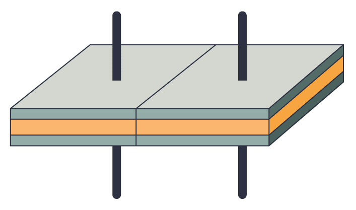
Another typical place where you’ll see capacitors connected in parallel is with microcontroller circuits. Microcontroller chips often have several power pins. And it’s common to place a capacitor from each positive power pin to ground.
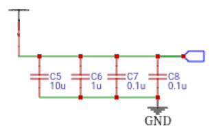
In this case, the point isn’t to get a new capacitor value, but instead to show you how many capacitors you’ll need for the circuit. Although they are connected in parallel, they’ll be distributed across the board.
Summary
To get the total value of capacitors connected in parallel, just add up the value of each. Ex five capacitors of 1 µF become 5 µF. And three capacitors of 100 nF become 300 nF.
For simple circuits, you usually only place them in parallel if you need a specific value that you don’t have available.
Copyright Build Electronic Circuits
Monday, 16 January 2023
Blocking radio waves and electromagnetic interference with the flip of a switch
Friday, 13 January 2023
Artificial nerve cells -- almost like biological
Thursday, 12 January 2023
Screen-printing method can make wearable electronics less expensive
Tuesday, 10 January 2023
The JK Flip Flop (Quickstart Tutorial)
The JK Flip Flop is a type of flip flop that can be set, reset, and toggled. It can be used for making counters, event detectors, frequency dividers, and much more.
In this tutorial, you will learn how it works, its truth table, and how to build one with logic gates.

What is a JK Flip Flop?
Flip flops are components that can store a digital value on their output. They have a Clock input (Clk) which determines when they can change the state of their output.
Contrary to what you’d think, the two inputs of the JK Flip Flop, “J” and “K”, are not abbreviations for what the pins do (which is the case for the S-R latch). They were chosen by its inventor Jack Kilby (JK) to distinguish his flip flop design from other types.
You can see a basic implementation of the circuit below. It’s based on the S-R latch and built with NAND gates:

The J and K inputs of the JK flip flop can be used to set, reset, or toggle the output, like this:
- J=1 and K=0 sets the output to 1
- J=0 and K=1 resets the output to 0
- J=1 and K=1 toggles the output
But for the flip flop to make any change, its Clock input must be 1. Check out the truth table below:
| Clk | J | K | Q | Description |
|---|---|---|---|---|
| 0 | X | X | Q | Clk in 0 no change in Q |
| 1 | 0 | 0 | Q | Memory (no change) |
| 1 | 1 | 0 | 1 | Set |
| 1 | 0 | 1 | 0 | Reset |
| 1 | 1 | 1 | Q̅ | Toggle |
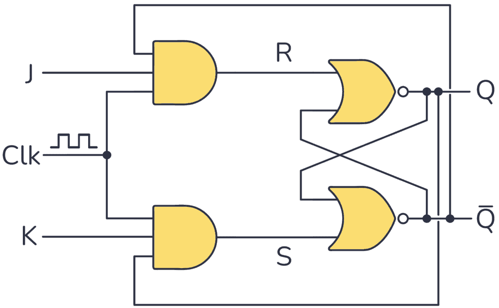
An alternative way to implement the basic JK flip flop circuit is using two AND gates and two NOR gates as follows (it works exactly like the one built with NAND gates):
Racing Problem
In principle, the basic implementation above works, but a timing problem arises. When the clock is “1” and you want to toggle the output, it will toggle really fast between “1” and “0” until the clock goes back to “0”. This issue is called a race condition.
You can solve this by making the the flip flop pulse-triggered or edge-triggered.
Pulse-Triggered JK Flip Flop
Below you have a pulse-triggered JK flip flop based on the Master-Slave principle:

As you can see, to build this configuration you need a basic JK Flip Flop circuit tied together with an S-R flip flop.
To understand how this version works check out its timing diagram below:

As soon as the clock makes a rising edge ↑, which is a change from 0 to 1 (0→1), it triggers the master section. As a result, the value of the outputs in this section changes. These signals are connected to the slave section, but this doesn’t trigger on the rising edge because the clock has been inverted.
Once the clock signal produces a falling edge ↓, a change from 1 to 0 (1→0), it triggers the slave section, causing the Q output to reflect the master’s output value.
So this circuit requires a complete pulse (0→1 →0) in order to change the output. That’s why this configuration is called pulse-triggered JK Flip Flop.
| Clk | J | K | Q | Description |
|---|---|---|---|---|
| 0 or 1 | X | X | Q | No pulse no change |
| 0→1 →0 | 0 | 0 | Q | Memory (no change) |
| 0→1 →0 | 1 | 0 | 1 | Set |
| 0→1 →0 | 0 | 1 | 0 | Reset |
| 0→1 →0 | 1 | 1 | Q̅ | Toogle |
Edge-Triggered JK Flip Flop
Unlike the Master-Slave design, you can trigger this edge-triggered JK Flip Flop just with either a rising edge ↑ or a falling edge ↓.
Below you have the timing diagram for one that triggers on the rising edge:

The above picture shows how this circuit just needs a rising edge on the Clk input to change the state of the output Q. And it will only change on the rising edge.
| Clk | J | K | Q | Description |
|---|---|---|---|---|
| 0 or 1 | X | X | Q | No rising edge no change |
| 0→1 (↑) | 0 | 0 | Q | Memory (no change) |
| 0→1 (↑) | 1 | 0 | 1 | Set |
| 0→1 (↑) | 0 | 1 | 0 | Reset |
| 0→1 (↑) | 1 | 1 | Q̅ | Toogle |
To build a JK Flip Flop that triggers only with rising edge signals, you can use a rising edge-triggered D flip flop, a NOT gate, and NAND gates as follows:

Questions?
Do you have any questions about how this type of flip flop works? Let me know in the comments below.
Copyright Build Electronic Circuits
Tuesday, 3 January 2023
Researchers discover new process to create freestanding membranes of 'smart' materials
-
CMOS (Complementary Metal Oxide Semiconductor) The main advantage of CMOS over NMOS and BIPOLAR technology is the much smaller power dis...
-
I was first introduced to logic gates when I was around 14 years old. I had heard that computers consisted of ones and zeroes. But I didn’t...
-
Do you need a MOSFET gate resistor? What value should it be? And should it go before or after the pulldown resistor? If you’re a bit impati...


