Friday, 24 February 2023
Electrodes grown in the brain -- paving the way for future therapies for neurological disorders
Thursday, 23 February 2023
Let there be (controlled) light
Tuesday, 21 February 2023
The switch made from a single molecule
Solid-state thermal transistor demonstrated
Beginner’s Guide to the Shift Register in Digital Electronics
A shift register is a common building block in digital electronics that is used to store and move bits, for example, to convert from serial to parallel data and vice versa.
It is basically a group of flip-flops that can store bits, and shift its stored bits sideways by one bit-position every time it is triggered. It is made using a series of D flip-flops with the output of one connected to the input of the next. Each clock pulse triggers a shift.
In this tutorial, you will learn the different types of shift registers, how they work, and how to build them using flip-flops.
What is a shift register?
A flip-flop can store just one bit of digital data, a 1 or 0. What if you want to store more than one bit? In order to store multiple bits of data, you need multiple flip-flops.

In digital electronics, a register is a group of flip-flops connected together to store multiple bits of data. For example, if you use eight flip-flops at once, then you are creating a register that can hold eight bits – or one byte.
The binary data in a shift register can be moved sideways within the register from one flip-flop to another. Registers that allow you to move bits sideways are called shift registers. There are four types of shift registers:
- Serial in – serial out
- Serial in – parallel out
- Parallel in – serial out
- Parallel in – parallel out

What is a shift register used for?
A shift register is commonly used in data storage, data movement, and data manipulation. The number of bits you can store in a shift register is equal to the number of flip-flops used.
You can find prebuilt shift registers ready to be used in a circuit for example in these chips:
- CD4015 – contains two 4-bit shift registers
- CD4014 – contains an 8-bit shift register with parallel outputs
- CD4017 – contains a ring counter (see below)
Among plenty more.
Circuit example for a shift register: Ring counters
Shift registers can be used in a wide variety of circuits. For instance, If you modify a serial in – parallel out shift register a little bit, you can create a ring counter circuit, like this:

To create a ring counter, you have to take the output from the last flip-flop in the register and connect it to the input of the first flip-flop. You also have to preset the first flip-flop to start with a 1.
You can do this by connecting its set input to the reset signal that all the D flip-flops share. This means that when you reset the circuit, it will start with 1 in the first flip-flop and 0 in the rest.
As a result, the 1 you set in the first flip-flop will shift around and around – in a “ring” – throughout the Q outputs.
The IC 4017 is a chip with this type of functionality, but with 10 outputs instead of just 4, like above. This makes for a fun chip you can use for example to create the Knight Rider LED bar, for example.
Now that you know a practical application of a shift register, here are more details about the different types you may come across.
What are the different types of shift registers?
Serial in – serial out (SISO) shift registers
The following circuit shows the structure of a serial in – serial out shift register made with D flip-flops:
This shift register accepts just one bit of data at the serial data input. It will move sideways to the next D flip-flop every time the Clk input receives a valid trigger signal. A valid trigger signal in flip-flops could be a rising edge – which is the change from a digital state of 0 to 1 ↑ – or a falling edge – a change from 1 to 0 ↓. In this tutorial, we are using flip-flops that trigger with rising edge signals.
As you can see, the above circuit has four D flip-flops. Let’s suppose you place a digital 1 into the serial data input. It will take four rising edge signals for the input bit to reach the serial data output. You can see the movement of bits in the SISO shift register timing diagram below:

Serial in – parallel out (SIPO) shift registers
This type of shift register is very similar to the SISO one we looked at above, but the difference is that a SIPO shift register has more than one output. This shift register has an output pin from each flip-flop so that you can access the bits in parallel. Let’s see its circuit:

This circuit receives one bit at a time in the serial data input. This bit will move from one flip-flop to the other – left to right – every time the Clk input in the D flip-flops receives a rising edge signal.
As the SIPO version has parallel outputs Q0, Q1, Q2, and Q3, you don’t have to wait for the input bit to arrive at the last flip-flop to be available; it will be at the Q3 output in the first trigger signal, in Q2 at the second one, with the third one it will be in Q1, and finally with a fourth rising edge in Q0. You have this behavior below:

A common practical example for the SIPO register is to add more output pins to an Arduino or other microcontroller. For example, check out this example using the 74HC595 with an Arduino.
Parallel in – serial out (PISO) shift registers
This shift register has a parallel input, which means that bits are loaded separately onto each flip-flop at the same time. In contrast to the input, the output has a serial format, meaning just one bit is output every time the flip-flops are triggered.

The circuit above consists of four D flip-flops, where the clock signal is shared among all the Clk inputs. Every D input is connected to a multiplexer, which receives the bit input (IN0, IN1, IN2, IN3) and the output of the previous flip-flop (left to right). Since the first flip-flop lacks a prior flip-flop, one input of the multiplexer is placed in a digital 1.
With this type of register a rising edge signal is not required to parallel load the register because the bits are already present in the inputs. Nevertheless, if you consider the above circuit with four flip-flops, then four rising edges will be required to unload the data. This will start with the bit in IN0, followed by the bit in IN1, then IN2, and finally IN3. Here you have an example with a timing diagram:

Parallel in – parallel out (PIPO) shift registers
This type of shift register acts as a multi-bit temporary storage device. Take a look at its circuit and try to guess why.

As you might have observed, in the PIPO shift register, the D flip-flops are not connected together through the D inputs and the Q outputs. Instead, they only share the clock signal.
The parallel input corresponds to every D input of each flip-flop (D0, D1, D2, D3). Because every flip-flop has the same clock signal in the Clk input, each will be triggered at the same time. When this happens, all the bits in the parallel input will move simultaneously to the parallel output (Q0, Q1, Q2, Q3). In other words, to transfer the entire data set, you only need one trigger signal.
This circuit wouldn’t qualify as a shift register since it doesn’t actually shift any bits. But with some additional logic gates between the output of one and the input of the next one, you can load data in parallel, shift the data, then get the shifted version of the data in parallel format.
Questions?
Do you have any questions about shift registers and their applications? Let me know in the comments below.
Copyright Build Electronic Circuits
Friday, 17 February 2023
Electronic metadevices break barriers to ultra-fast communications
TFT strategy to enhance flexible display panel performance
What is a Light-Emitting Diode (LED)?
A Light-Emitting Diode (LED) is a small component that lights up when there is current flowing through it. It’s used in light bulbs, displays, lighting decorations, and much more. In electronics, it’s often used for showing the state (is the gadget turned on?).
You can see the light-emitting diode everywhere! In laptops, on mobile phones, on cameras, on toys, in our car +++.

It’s a type of diode, so it only works when you connect it with its anode towards your battery’s plus terminal.
Chances are you will be working with LEDs a lot when you start learning electronics. They are cheap and simple to use, and it’s a great way to check if your circuit is working properly or not.
How Light-Emitting Diodes Work
To understand how a light-emitting diode works, you need to get into the physics part of semiconductors. Simply explained, the LED is similar to a standard diode, but with the addition of a phenomenon called Electroluminescence.
The LED is made of electroluminescent materials, such as gallium arsenide, and has a p-n junction, just like a standard diode. When electrons in the semiconductor recombine with holes, they release energy in the form of photons, which is what makes up light.
The energy required for electrons to cross the band gap of the semiconductor decides the color of the light.
How To Connect A Light-Emitting Diode
An LED has two pins – anode and cathode:
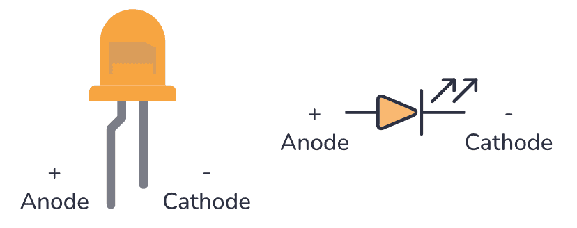
The anode is the longest pin. This is the pin you connect to the most positive voltage. The cathode is the pin you connect to the most negative voltage.
They must be connected correctly for the LED to work. If you connect them in the opposite direction no current will flow, just as with standard diodes.
In addition to connecting the LED with the correct orientation, it’s important to connect it in series with a resistor to limit its current. A resistor connecting in series with an LED is called a current-limiting resistor.
Simple LED Circuit Example
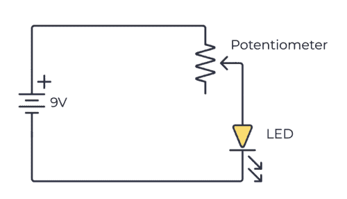
Here’s a simple example of how to connect a light-emitting diode in a circuit:
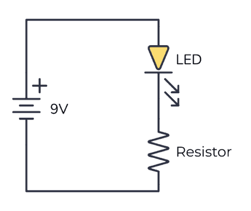
Usually, an LED needs about 2-3 volts and about 1-10 mA to light up. But this varies among different LED types. The easiest way to find this information is to look it up in the datasheet (look for LED forward voltage and Test Current) – or ask the store where you bought it.
You don’t have to worry too much about the voltage. For most standard LEDs, if you have a voltage of around 9V and use a resistor in series of around 1 kΩ to 10 kΩ, the LED will “grab” the voltage it needs.
If you run too much current through an LED, it will get really hot and break down. That’s why the resistor is there – to control how much current that goes through the LED. The only time you don’t need the resistor is when you have a battery or other voltage source that provides exactly the voltage your LED needs.
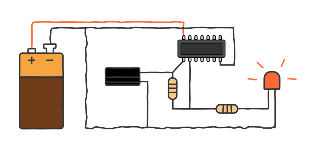
How To Blink An LED
If you want to blink an LED, you need to build an oscillator circuit that will turn the LED on and off. LEDs with this circuit built-in exist. But normal LEDs won’t blink without this circuit.
There are several ways to blink an LED, but one of the easiest ones to both build and understand is the blinking LED circuit based on a NOT gate.
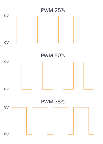
How To Adjust the Brightness of an LED
There are two ways to adjust the brightness of an LED.
(1) You can turn the LED on and off really fast (using PWM), and the ratio between being on and off will decide how bright the LED will seem to the human eye:
(2) Or you can control the current going through the LED, which directly translates to brightness. More current gives you more brightness. The resistor in series with the LED sets the current. So by changing the resistance of the resistor, you can change the brightness.
A potentiometer is a variable resistor. If you add the potentiometer in series with the LED, you can turn the knob of the potentiometer to adjust the brightness of the LED.
Light-Emitting Diode Colors
LEDs come in many colors. Common colors are red, green, yellow, amber, blue, and white. Or a combination of colors, like the RGB LED.
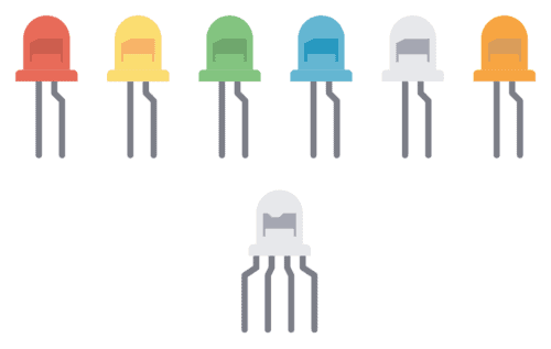
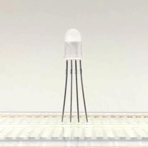
RGB LEDs (Multicolor LEDs)
RGB LEDs are LEDs that have three light-emitting diodes inside; red, green, and blue. By controlling the brightness of each color, you can combine them to create other colors.
Bicolor LEDs
Bicolor LEDs are light-emitting diodes with two colors. They are made so that if you set up the current to flow in one direction, you get one color, while in the other direction, you get a different color.
A typical color combination is red and green which you can use to show if your gadget is working correctly (green) or nor (red).
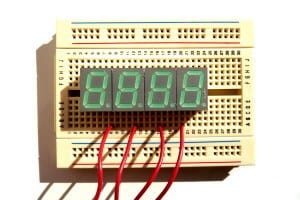
The 7-Segment LED Display
LEDs are also used to build displays. One of the simplest displays you can build with the LED is the 7-segment display. It consists of seven LEDs that you can turn on or off to display a number:
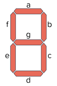
If you turn on all the segments, you get an 8. If you turn on only the b and c segments, you get a 1. These displays are common in alarm clocks and other places where you only need to show a number.
Copyright Build Electronic Circuits
Monday, 13 February 2023
Atom-thin walls could smash size, memory barriers in next-gen devices
Chiral phonons create spin current without needing magnetic materials
Friday, 10 February 2023
Beyond lithium: A promising cathode material for magnesium rechargeable batteries
Thursday, 9 February 2023
What is a Diode?
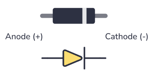
A diode is a component that lets current flow in one direction and blocks it from flowing in the other direction. It has two pins; anode and cathode.
The diode symbol looks like an arrow pointing toward a line. The line represents the cathode side, and so does the line marking on the diode component itself.
How To Connect A Diode in a Circuit?
A diode will block or let current flow, depending on how you connect it in a circuit. Below you can see an example circuit.

In the circuit above the diode is connected in the right direction. This means current can flow through it so that the LED will light up.
But what happens if we connect it the other way around?

In this second circuit, the diode is connected the wrong way. This means that no current will flow in the circuit and the LED will be turned OFF.
What Is a Diode Used For?
A standard diode is can be used for a range of things, from creating sound effects to power supplies. Below you can see a few circuit examples with an explanation of what the diode is used for:
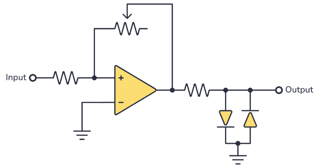
Sound Effects Clipping: By placing two diodes in parallel in opposite directions, you can get a clipping effect which creates an overdrive sound effect, often used in guitar pedals.
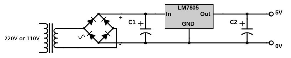
Converting from AC to DC: Sometimes diodes are used to convert from AC to DC by placing four diodes to create a bridge rectifier. This is often used after a transformer in a power supply, followed by a voltage regulator.
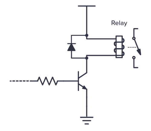
Protecting from voltage spikes: Components like motors and relays are basically inductors, which means their current will try to keep on flowing after the power is shut off. Diodes are used to safely discharge them.
How a Diode Works
The diode is created from a PN junction. You get a PN junction by taking a negatively doped and positively doped semiconductor material and putting it together.

At the intersection of these two materials, a depletion region appears. This depletion region acts as an insulator and refuses to let any current pass.
When you apply a positive voltage from the positive side to the negative side, the depletion layer between the two materials disappears and the current can flow from the positive to the negative side.
When you apply a voltage in the other direction, from the negative to the positive side, the depletion region expands and resists any current flowing.
Things To Note About Diodes
- You have to apply enough voltage in the “right” direction – from positive to negative – for the diode to start conducting. Usually, this voltage is around 0.7 V to 1 V.
- It has limits and cannot conduct unlimited amounts of current.
- Diodes are not perfect components. If you apply voltage in the wrong direction, there will be a little bit of current flowing. This current is called leakage current.
- If you apply a high enough voltage in the “wrong” direction, the diode will break down and let current pass in this direction too.
Types of Diodes
There are many different types of diodes. The most common ones are:
- Signal diode
- Rectifier diode
- Zener diode
- Light-Emitting Diodes (LED)
- Schottky Diode
- Photodiode
- PIN diode
Signal and rectifier diodes are pretty much the same things except that rectifier diodes are built to handle more power.
Zener diodes are diodes that make use of the breakdown voltage when applying voltage the “wrong” way. They act as very stable voltage references.
Schottky Diodes have a lower forward voltage drop and faster switching speeds than standard signal diodes.
Photodiodes are diodes that are sensitive to light. They let current flow through them when exposed to light.
Light-Emitting Diodes (LED) are components that light up when current flows through them.
Questions
Do you have any questions about diodes or any feedback you want to share? Let me know in the comment field below!
Copyright Build Electronic Circuits
Wednesday, 8 February 2023
Wear and forget: An ultrasoft material for on-skin health devices
Tuesday, 7 February 2023
Biosensor could lead to new drugs, sensory organs on a chip
-
CMOS (Complementary Metal Oxide Semiconductor) The main advantage of CMOS over NMOS and BIPOLAR technology is the much smaller power dis...
-
I was first introduced to logic gates when I was around 14 years old. I had heard that computers consisted of ones and zeroes. But I didn’t...
-
Bluetooth Controlled Electronic Home Appliances is a simple project, where we can control different electrical appliances and electronic de...


