Saturday, 29 April 2023
A transistor made of wood
Tuesday, 25 April 2023
Zener Diode Basics (A Beginner’s Guide)
In this guide, you’ll learn exactly how a Zener diode works and how to use it in circuits.
Did you know that some of the common things you can build with Zener diodes include simple power supplies and guitar pedals?
Sounds interesting? Let’s jump in!
What Is a Zener Diode?
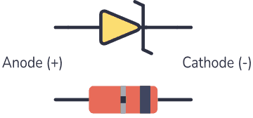
A Zener diode is a type of diode that is often used for voltage regulators and shaping waveforms.
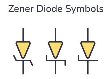
Its symbol is an arrow pointing towards a crooked line. There are actually three different ways you can draw the Zener diode symbol in schematics:
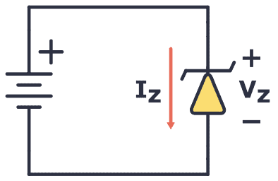
While a normal diode only allows current to flow through a circuit when it is forward-biased (current going from anode to cathode), the Zener diode also works when it is reverse-biased (current going in the opposite direction).
With standard diodes, if you place it in reverse, no current flows.
At least, so it appears. But actually, if you apply enough voltage in reverse, current will start to flow.
This voltage is called the breakdown voltage of the diode.
For example, the rectifier diode 1N4001 has a breakdown voltage of 50V.
The Zener diode is basically the same as the standard PN junction diode. However, it is specially designed to work in reverse bias with a low and specified reverse breakdown voltage.
So, why is that interesting?
Because you’re not limited to the standard forward voltage of 0.7V. You can design the breakdown voltage to be for example 3.3V or 12V – or many other voltages. The manufacturers call this Zener Voltage (Vz).
This means a Zener diode can act as a voltage regulator because it keeps the breakdown voltage at a nearly constant value across its terminals.
How To Make A Zener Diode Voltage Regulator
Making a voltage regulator is easy with the Zener: Just add a resistor!
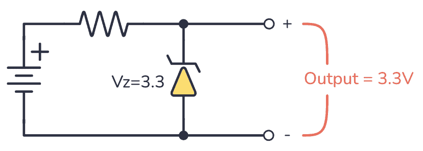
Here’s how it works:
When a voltage (must be higher than the Zener voltage) is applied across the resistor and Zener diode, the diode starts conducting in reverse and keeps the voltage drop across it at a constant value of 3.3V.
The rest of the voltage drops across the resistor. This means the resistor acts as a current-limiting resistor so that you can easily calculate the current by using Ohm’s law.
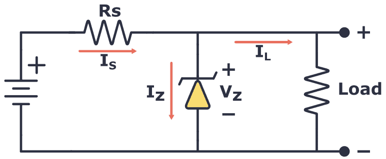
The resistor (RS) limits the maximum current that can flow through the circuit. If there is no load connected to the circuit all the current flows through the Zener diode, causing it to dissipate its maximum power.
A smaller value of resistor RS gives you a higher maximum current. But at the same time, you have to make sure that you don’t exceed the maximum power rating of the Zener. Therefore, it’s important to choose the right value of series resistance.
Example: Choosing a resistor for a 12V to 3.3V voltage regulator
In this example, you’re going to use a Zener diode that can handle up to 2W of power. What’s a suitable value for the resistor (RS)?
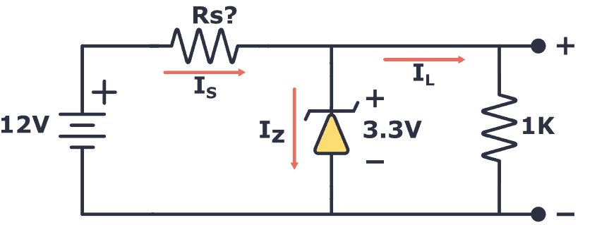
First, you need to find the maximum current that can flow through the Zener diode:

That means that the minimum value of the resistor is:

So a value of 14.5 Ω is the absolute minimum. But you can use higher resistances of course.
Next, you need to check how much current your load needs. The load resistor is 1 kΩ, so its current is calculated as follows:

That’s much lower than the 0.6A you’d get from the 14.5 Ω resistor, so no problem here.
If you want to use a higher resistor value, just use the following formula with your chosen resistor value and make sure that it’s above the current you need for your load:

For example, if you want to use a 100 Ω resistor, this would give you a maximum current of:

Still, high above the needed 0.0033A for the load, so you’re good to go.
That said, Zener diodes have their disadvantages. Check out this article about why Zener diodes make lousy voltage generators.
Wave-Shaping With the Zener
In the previous example, you saw how the Zener works with DC power. However, what happens when it’s used with AC power? How would it react to a constantly changing signal such as an audio signal?
Check out the following circuit:
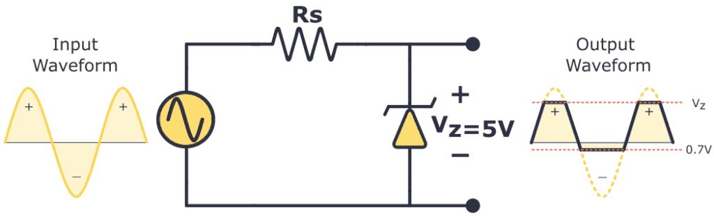
In the above diagram, the Zener diode has a VZ of 5V, so if the waveform exceeds this limit, the diode will “clip off” the excess voltage from the input, resulting in a waveform with a flat top maintaining a constant output of 5V.
When forward-biased, the Zener diode behaves like a regular diode. So when the waveform reaches negative values below 0.7V, the Zener acts like a typical rectifier diode, resulting in output clipping at -0.7V.
Zener Diode Example: Distortion Guitar Pedal
Diode clipping and clamping circuits can shape a waveform to produce an output waveform with a different shape. A clipper circuit clips off the positive or negative part of an AC signal, which is why they are commonly used as waveform shaping circuits.
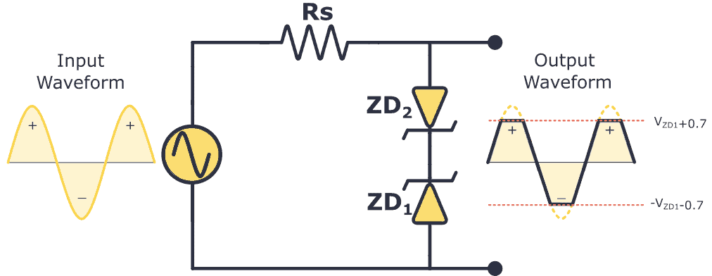
When you cut off the top of an audio signal, it sounds distorted. This is exactly what you want in a distortion guitar pedal!
But the output signal of an electric guitar isn’t high enough to be clipped. So in order to clip it, you must amplify it first. Here’s a basic guitar distortion pedal circuit that uses Zener diodes to distort the sound:
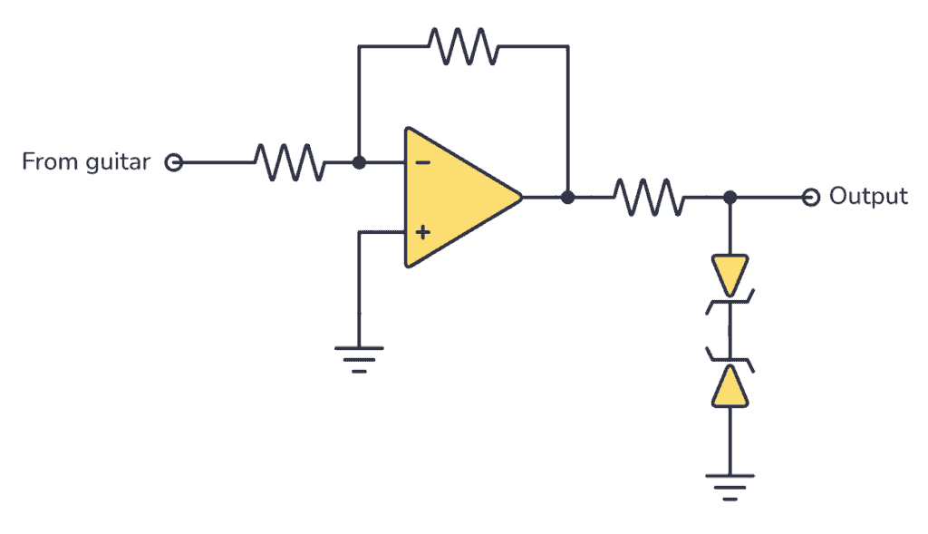
So, if you build the circuit above the output waveform will be clipped at the VZ voltage plus 0.7V, which is the forward voltage drop of the other diode.
Zener Diode Characteristics (The I-V Graph)
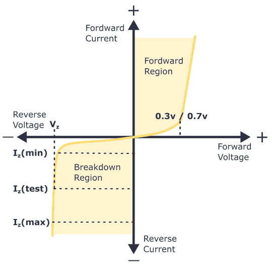
The I-V characteristics curve of a Zener diode is shown in the image above. By studying this graph, it becomes clear why Zener diodes are employed in reverse bias.
By observing the behavior of a Zener diode, you can notice that as the reverse voltage rises, the reverse current also increases gradually until it hits the Zener knee current, IZ (min). At this point, the breakdown effect starts, and the Zener impedance (ZZ), which is the internal resistance of the diode, begins to rapidly decrease as the reverse current increases.
In general, the breakdown voltage of the Zener (VZ) is fairly constant, although it increases slightly with increasing Zener current (IZ). VZ is commonly set at a value of the Zener current known as the IZ (min).
A Zener diode’s ability to maintain almost constant voltage in its breakdown region makes it suitable for regulating voltage even in the simplest voltage regulator applications.
A voltage regulator’s main role is to deliver a steady output voltage to a load connected in parallel. This is even when the supply voltage has ripples or the load current varies. Zener diodes can maintain a constant voltage output as long as their reverse breakdown region holding current does not drop below IZ (min).
Common Zener Diode Voltages
Here you have a table with the most common Zener voltages in diodes of 0.3 W and 1.3 W.
| 0.3W BZX55 zener diode | |||||||
| 2.4V | 2.7V | 3.0V | 3.3V | 3.6V | 3.9V | 4.3V | 4.7V |
| 5.1V | 5.6V | 6.2V | 6.8V | 7.5V | 8.2V | 9.1V | 10V |
| 11V | 12V | 13V | 15V | 16V | 18V | 20V | 22V |
| 24V | 27V | 30V | 33V | 36V | 39V | 43V | 47V |
| 1.3W BZX85 zener diode | |||||||
| .3V | 3.6V | 3.9V | 4.3V | 4.7V | 5.1V | 5.6 | 6.2V |
| 6.8V | 7.5V | 8.2V | 9.1V | 10V | 11V | 12V | 13V |
| 15V | 16V | 18V | 20V | 22V | 24V | 27V | 30V |
| 33V | 36V | 39V | 43V | 47V | 51V | 56V | 62V |
Copyright Build Electronic Circuits
Saturday, 22 April 2023
Cheaper method for making woven displays and smart fabrics -- of any size or shape
Friday, 21 April 2023
New findings pave the way for stable organic solar cells that may enable cheap and renewable electricity generation
Thursday, 20 April 2023
Informed by mechanics and computation, flexible bioelectronics can better conform to a curvy body
Now you can be comfortable in your e-skin
Wednesday, 19 April 2023
A team creates 'quantum composites' for various electrical and optical innovations
Physicists discover transformable nano-scale electronic devices
Thursday, 6 April 2023
Fully recyclable printed electronics ditch toxic chemicals for water
Wednesday, 5 April 2023
Solid-state lithium-sulfur batteries: Neutrons unveil sluggish charge transport
Monday, 3 April 2023
What is an Integrated Circuit (IC)?
An integrated circuit is simply any type of circuit, made to fit onto a small chip. Sometimes referred to as a chip, a microchip, or an IC. It can be a microcontroller, an amplifier, a Bluetooth module, or anything in between.
By making a circuit on a small chip, it’s much easier to build advanced projects. Let’s say you want to make a tracking device for your car. You can find a GPS chip for positioning, a GSM chip to send text messages with the position, and a microcontroller chip to control everything. Then create a printed circuit board design to connect them all.
This would be pretty much impossible to do if you were to design everything from scratch with individual components. Integrated circuits make building circuits so much easier!
Back in 2008, I made my own integrated circuit as I was doing my master’s degree at the University of Oslo. So if you want to learn how these tiny and powerful components are actually made, from a practical point of view, (and how you can make one yourself as a hobbyist), read on!
What are Integrated Circuits?
An integrated circuit is made up of lots of miniature versions of basic components such as transistors, resistors, and capacitors. The functionality of the chip depends on how the components have been connected inside. It can be a radio transmitter, a collection of logic gates, a microcontroller, or any other circuit you can think of.
Every IC comes with a datasheet that explains what it does, what each pin’s function is, and how to use it.
Common IC Series
- 4000 series IC (digital integrated circuits)
- 7400 series IC (digital integrated circuits)
- LM-series of IC (analog integrated circuits)
How Are Integrated Circuits Made?
To design an integrated circuit from scratch, you need to use software for this specific purpose. In the software, you draw different rectangles to create your circuit. The different rectangles represent different types of material. And different combinations of those materials give you different components.
You actually design every component from scratch by putting together different materials. Below you can see a cross-section of a chip with the materials needed to design an nMOS and a pMOS transistor:
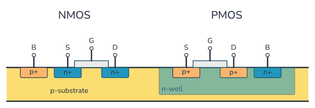
A typical integrated circuit consists of mostly transistors like the one above. So designing an IC is a lot of copying and pasting, then making sure you connect the transistors so that they make up the circuit you want.
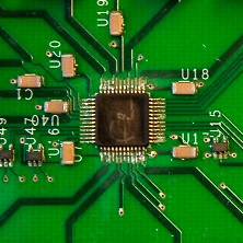
Here is the design of the chip I made back in 2008. Each color is a different layer of material:
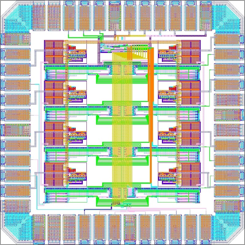
This design is then transferred to a silicon wafer by using a process of etching and stereolithography. (Learn more about this process here)
What Does an Integrated Circuit Do?
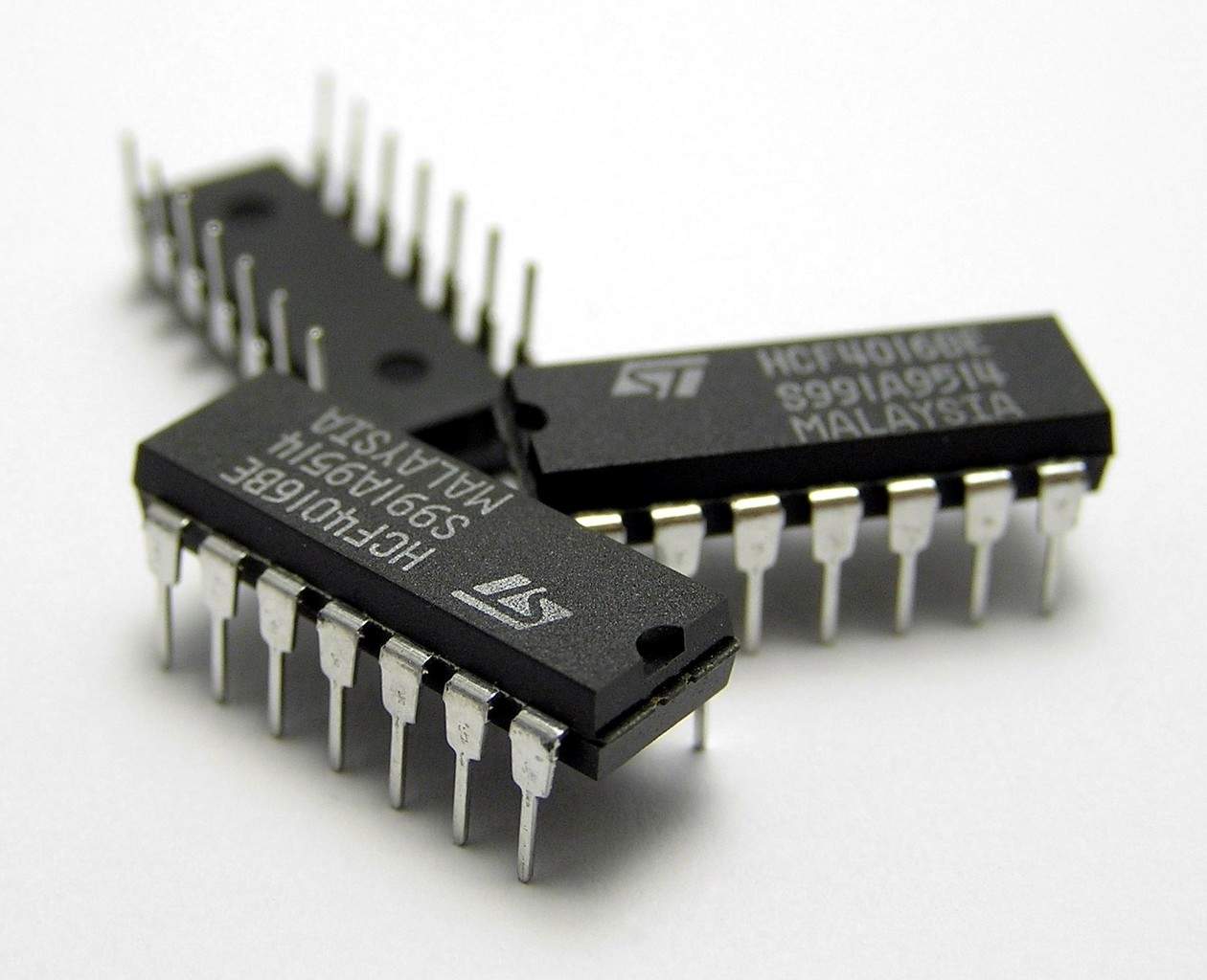
If you have an integrated circuit, but you don’t know what it does, don’t worry. Usually, it is very easy to figure out what it does. Just take the model number that you find on the top, and type it into Google with “datasheet” after.
Most likely, you will find a PDF file of the datasheet. The datasheet is a technical document that describes the component. By opening and reading the first page of the datasheet, you should be able to get an understanding of what it does.
Next, find the pinout or pin description section to figure out the function of each pin. And have a look at the Typical Application section to see an example of how to connect the chip in a circuit.
What is an Application-Specific Integrated Circuit (ASIC)?
The difference between an application-specific integrated circuit (ASIC) and a normal integrated circuit is that the ASIC is specifically designed for something or someone, instead of being mass-produced.
To say it in another way – an ASIC is a custom integrated circuit. It’s something you design for a specific purpose. But it’s designed and made with the same methods as a normal integrated circuit.
You don’t have to be a big corporation to make an ASIC. You can make your own custom integrated circuit as a hobbyist too! Just have a look at the Tiny Tapeout project.
Questions?
Do you have any questions about the integrated circuit or how to make one? Let me know in the comments section below and I’ll do my best to answer as soon as possible.
Copyright Build Electronic Circuits
Sunday, 2 April 2023
Plastic transistor amplifies biochemical sensing signal
Magnon-based computation could signal computing paradigm shift
Saturday, 1 April 2023
Modern origami method creates glass shapes by folding
-
CMOS (Complementary Metal Oxide Semiconductor) The main advantage of CMOS over NMOS and BIPOLAR technology is the much smaller power dis...
-
I was first introduced to logic gates when I was around 14 years old. I had heard that computers consisted of ones and zeroes. But I didn’t...
-
Do you need a MOSFET gate resistor? What value should it be? And should it go before or after the pulldown resistor? If you’re a bit impati...


