Friday, 31 May 2019
Organic laser diodes move from dream to reality
Thursday, 30 May 2019
Laser technique could unlock use of tough material for next-generation electronics
Scientists design organic cathode for high performance batteries
Lights, camera, fracture
Beyond 1 and 0: Engineers boost potential for creating successor to shrinking transistors
Best Robot Dog Toys for Kids in 2019 Reviews
Since our childhood toys played an important role in shaping our lives. They kept us entertained, helped to develop our cognitive functions, motor skills. So, if you want to purchase a toy for your baby boy or girl, you need to be sure regarding the quality of the toy.
One of the most popular type of toys are the dog toys. You can find the soft and cuddly ones in the stores but these days with the advancement of technology robot dog toys are available in the stores. These toys are amazing, a proper replacement for actual pet dogs. The almost act like the real ones and using the advance sound and visual modifications they are designed to sound and feel like real puppies.

But different manufacturers are designing them and a lot of varieties are available on the market and online shops. So, it would be quite hard for you to get the best robot puppy for your kid as there are a lot factors you need to consider like the price, quality, sound, movements and even the popularity of the manufacturer. So, there is a detailed buying guide on the factors you should look for while buying it on this article.
Also, in order to reduce the burden of searching and looking for the dog toy we have compiled a list of 10 best companion robot dog toys for you. They are detailed and listed below.
Top 10 Best Robot Dog Toys Reviews in 2019
1. Ageless Innovation Joy For All Companion Pets Golden Pup

This is called the Golden Pup, designed by Hasbro, it’s one of the best companion pet toys available on the market. It has a very simple but attractive design with a fur that looks and feels real. It also features heartbeat, the most realistic bark and life like responses. This is an amazing interactive puppy designed for comfort and convenience. According to us, this is the best interactive puppy in this list which deserved to be on the first place.
Pros
- The advanced BarkBack tech was used to makes it sound so real.
- Touch sensitive, responds to your touches accordingly like a real puppy.
- The soft and quality fur and the real-life design makes it very comfy and attractive.
- It runs on 4 C batteries which are included in the package.
Cons
- The fur quality is not so good.
- Battery runs out pretty quickly.
2. FurRealGoGo My Walkin’ Pup Pet

This interactive dog toy provides rich real pet like experience. This toy is engaging, exciting and creates a life-long bond with the kids. You use the leash controller to take her for a walk, you can even pet and talk to her. She responds to your voice and the movements are life-like. This Get Up&GoGo puppy is designed by FurReal and it is one of the best looking interactive robot puppy we have seen; and thus currently it is holding the 2nd position on our list.
Pros
- A very attractive robot puppy, perfect for kids.
- Comes with a remote control leash, you can take it to walk. Feels like a real pet.
- If you pet it, it sits down.
- Covered with soft fur which is very life-like.
- Sounds just like a real puppy.
Cons
- Does not have a wrist band or a remote.
- Bit over-priced.
3. Electronic Pet Dog Interactive Puppy – Robot Harry

The cuteness and functionality of this robot dog has attracted a number of customers, including us. This is the 3rd toy robot on our list and it is quite attractive. The big cute eyes of robot puppy Harry attract kids. It is a portable battery operated toy. Very durable and capable of interacting with its owner in a fun lovable way. Although the sounds are a bit below par, it makes it up with its functionalities.
Pros
- This robot dog works on most of the surfaces.
- It is equipped with Bump n Go feature.
- The robot dog harry runs on 3AA batteries.
- The sensors are touch sensitive and they are very responsive.
- The tuff plastic case provides it an extremely long life time and much wanted durability.
Cons
- Robot Harry is a bit on the expensive side.
- The sound it makes are not good at all.
4. WowWee Chippies Robot Toy Dog

This toy robot is equipped with advanced technology and its superior design made us put it in the 4th position on your list. WowWee is a famed company known for their toy robots and Chip is their trademark product.
The design is quite different than other robot dogs, they completely threw away the idea of making it looking life-like, instead they gave it a futuristic robo-like look which is adored by kids. A remote control and an intruder alert are also added. If Chip sensed an intruder, its eyes turn red immediately and tell to stay away.
Pros
- Chip is equipped with advanced technology.
- The design is baby proof.
- Very durable.
- Addition of the intruder alert is great.
- A remote is added to control is from a distance.
Cons
- The toy has attached wheel under its 4 legs, the wheel makes constant noise which is very annoying.
5. Westminster Chi-Chi Chihuahua

The Chihuahua is a very popular breed of puppies and Westminster went straight for it. It is one of the best looking cuddly robot dog for your kids. The inside is made of plastic but the outside is coated with good quality fur that is almost life-like, making it best suited for the 5th position on our list.
It acts like a real Chihuahua too. It can move its tail, nod its head and makes cute noises. Very suitable for kids above the age of 4.
Pros
- The fur is very soft and realistic.
- Suitable for kids above the age of 4.
- Movements are very real.
- It can nod, walk and even move its tail.
Cons
- If your kid is older then, this puppy will be too small for them.
6. Little Live Pets – Rollie

The 6th position is taken by Rollie. It may not be so technologically advance but it is the cutest puppy you will ever find. It has the most amazing look, the fur is soft and it is super huggable making it one of the best choices for you.
It can kiss, cuddle and move just like a real puppy. It also makes cute puppy sounds.
Pros
- It’s cute and cuddly.
- The most huggable puppy ever.
- It licks and kiss and it is very adorable.
- It can also wag its tail and makes realistic movements.
Cons
- The build quality is not so good.
7. Fisca Remote Control Dog Programmable Robot Puppy

The 7th position is taken by the robot dog manufactured by fisca. It is an amazing intelligent and programmable robot dog that interacts with you if you just pat its head. It is great for children and its 4 dance number with music makes it so cute and attractable to our kids.
It has a very smooth and shiny surface and a power saving mode designed to preserve energy.
Pros
- The setup is very easy.
- It can dance with music, walking movement is also available.
- Remotely controllable. The remote control and its batteries are included.
- After charging it can play for an hour.
Cons
- Charging takes too long.
8. Contixo Puppy Smart Interactive Robot Pet Toy for Kids

This is the smart puppy designed by Contixo. It is responsive to voice and even touch and it also comes with an app. The app control is amazing and it is integrated with quality Bluetooth speakers.
A rhythm feature is also added which makes the one of the best robotic puppies and 8th best choice on our list.
Pros
- It has a futuristic robot type look.
- If you just rub its chin, it will react.
- It is also susceptible to voice commands.
- An infrared motion sensor is also added.
- The app controlled features are amazing.
Cons
- The operation is just too complicated for the kids.
9. Zoomer responsive Robotic Dog with Voice Recognition

The playful pup by Zoomer is an ideal friend for your child. It responds to your voice and capable of learning new tricks. It has a smooth robotic body but it has pair of cute fur coated ears and a fur coated tail. This pet robot is very adorable and responds to your touch and it deserves to be at the 9th position on your list.
Needless to say, this puppy is very interactive and engaging. It will keep your kid busy for a long period of time. It barks and movements are excellent too.
Pros
- The design is outstanding and different.
- Responsive if you touch it.
- It learn ticks like “Puppy Sit” or “Lie Down”.
- It barks and begs.
Cons
- The use is too complicated.
- Not very durable.
10. Dimple Wireless Remote Control Robot Puppy

The Dimple’s wireless toy robot is very responsive to voice commands. This hi-tech interactive puppy has a sleek design and with the help of the provided remote control you can operate this puppy even from 50 meter distances. This futuristic looking robot puppy is the last product on our list due to its conveniently accessible nature.
It has an interesting design, the eyes are equipped with large LED lights which can turn into screen and display alphabets. Basically, this robot toy helps to educate your kid.
Pros
- It comes with a rechargeable battery.
- It can sing, 4 cute songs are included.
- It is designed with BPA free plastic.
- Comes with a remote control which can be used from 50 meter distance; very convenient.
Cons
- There are no additional features.
- Not very engaging.
Robot Dog Toys Buying Guide
After all you got an exclusive insight into our selection of the 10 best robot pet puppies. But it is still not enough for you to purchase the best robot pet within your price range. If you are getting a robot dog for your kid you have to learn about a few attributes in order to choose the right one. Learn about the attributes in details, below;
-
Type of Robot Toys
First, you need to decide which type of robot dog you want to get for your kid. These toys come in different sizes and different looking ones are also available. So, you need to select the one that your kid will really love to play with, if you have a toddler then you must buy a small one, it will be easier to manage. The bigger and bulkier toys are suitable for older kids. But finally, you need to check the design. It needs to be attractive or your kid won’t like it.
-
Technology
These are not just toys, the advancement and technologies are also related to it. So, you also have to think about the technology used on the toy too. Generally, most of such toys look similar but the technology used inside is completely different. So, you need to remember these things while you are buying these toys. Thoroughly check the toy, see if can move around properly, the sound it makes and even the additional features. Then, get the one that shows maximum promise.
-
Durability
Just remember that you are getting this toy for your little kid; so, it has to face a tremendous amount of abuse. They can throw it or smack it on the floor and even bite it. So, there is a big chance that it will get destroyed pretty soon but if you want to get value for your money you need to choose a model that is capable of withstanding the abuse a bit longer. You have to makes sure that material used on it are the best and there are a lot of movable parts; so, they need to be unbreakable and can take up wear and tear.
-
Safety
The safety is obviously important! They are definitely fun to play with but you also have to remember that you are going to give it to your little kid and these are electronic products. There are obviously the Chocking hazards! So, look for things that can cause it while buying it, also check the material of the fur, if it is cheap it can cause irritation or even rashes. Lastly, check the batteries as they need to be in a safe place in order to prevent accidents.
Conclusion
Toys are important and they are one of the most essential parts of your kid’s life. Hopefully, after going through this article you won’t have any problems to purchase the best interactive dog toy for your kid that fits perfectly within your price range. You can simply choose any one from the mentioned list or use the buying guide to make a different choice.
Our personal recommendation is the Ageless Innovation Joy For All Companion Pets Golden Pup. The life-like responses, heartbeat and the close to perfect bark are its USP. It also looks very real when compared to other products here. Given the price and the overall package, it is very hard to beat this product!
The post Best Robot Dog Toys for Kids in 2019 Reviews appeared first on Electronics Hub.
Wednesday, 29 May 2019
How small can they get? Polymers may be the key to single-molecule electronic devices
Sunday, 26 May 2019
A simple, yet versatile, new design for chaotic oscillating circuitry inspired by prime numbers
Friday, 24 May 2019
Adding a carbon atom transforms 2D semiconducting material
How To Use A Breadboard [VIDEO]
 A breadboard is a really simple way to put together a circuit. You don’t have to solder, just plug in the components.
I love to use breadboards for testing out new circuits quickly.
You can build really cool things on the breadboard. For example, check out this color-changing lamp or this radar that detects my breath.
If you don’t know how to use a breadboard, don’t worry. It’s very easy.
Just check out my video:
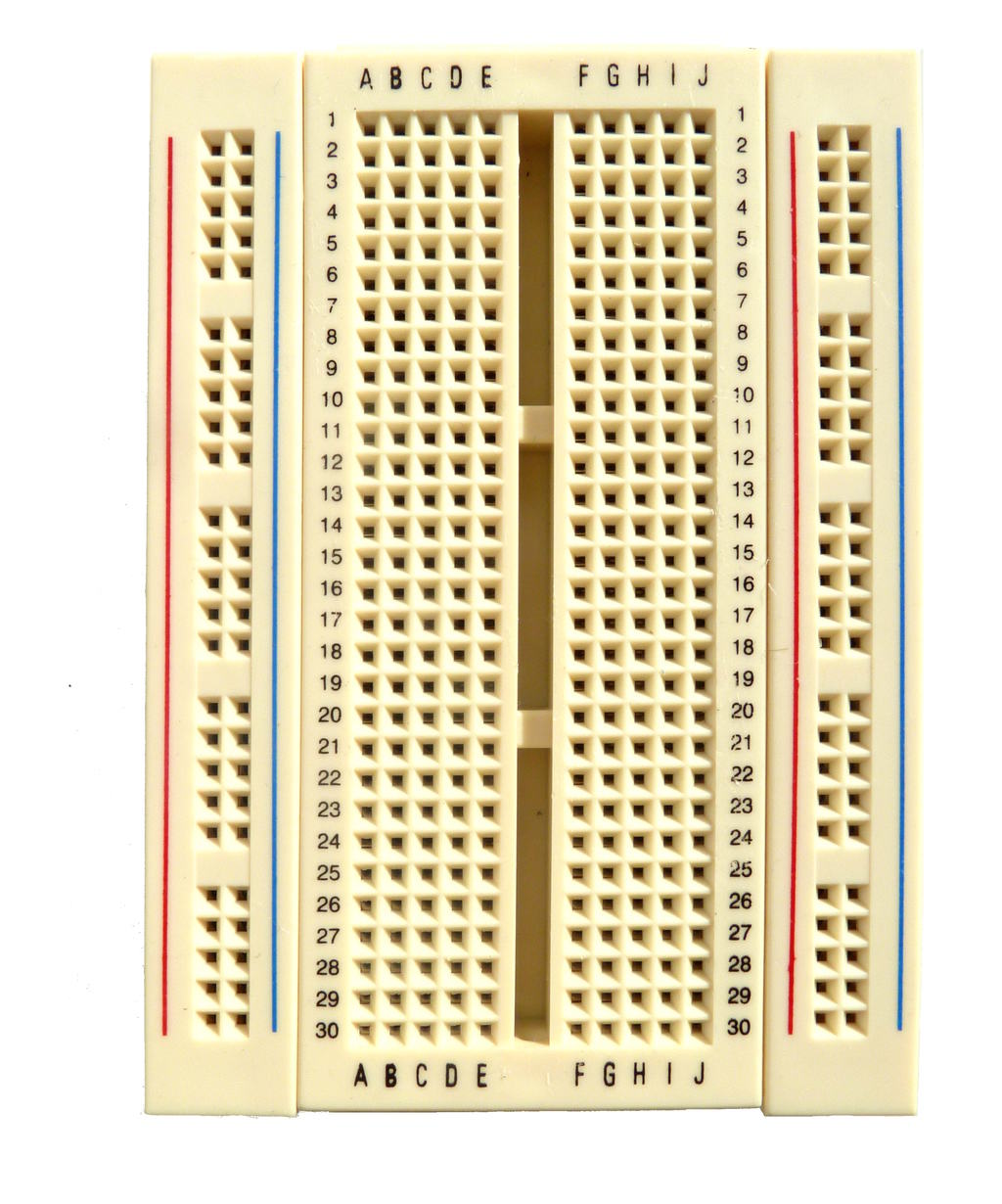
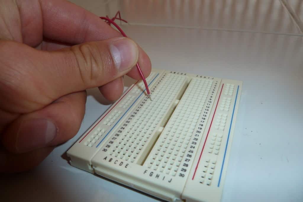
Where To Connect Components On A Breadboard
The breadboard has connections between its holes. Some vertical connections and some horizontal connections.
Power Supply On The Sides
It’s common to use the vertical columns on the left and right for connecting the power supply. Each of these columns are connected vertically. So, if you connect 5 volts on the top hole of one of the side columns, you will have 5 volts in all the holes of this columns.
Some larger breadboards are split into two, so that the upper half of the left and right columns is connected and the lower half is connected. This is indicated by the vertical blue and red lines.
Components In The Middle
You connect your electronic components in the middle of the board. On the picture above, you can see that each column is marked with a letter, A to J. Each row is marked with a number, 1-30.
For each row, holes A to E are connected and F to J are connected. The gap in the middle splits the row into two parts.
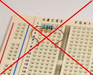
Below you can see a correct and a wrong connection of a resistor:
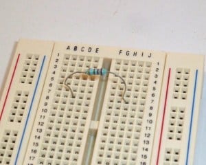
You can also connect the resistor from one row to another.
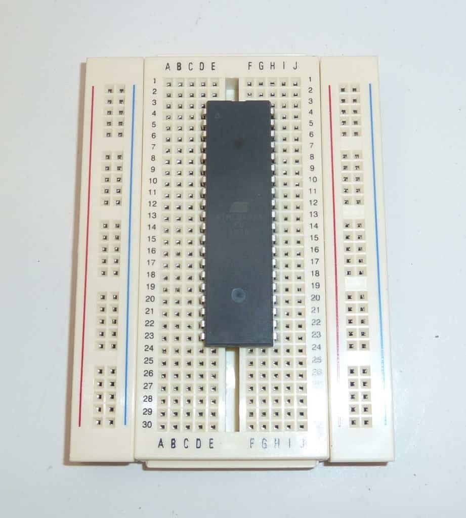
If you want to connect a chip, you need to connect it across the gap in the middle like this:
Connecting Components On A Breadboard
To connect a component or a wire to the breadboard, simply push it into a hole.
The best wires to use are 22 gauge single strand wire. Single strand means the wire has one solid core inside (as opposed to lots of tiny wires wrapped together).
What Can You Build With A Breadboard?
Breadboards are often used to build a prototype or to test a circuit. Or a part of a circuit that you are unsure about.
For example, let’s say you wanted to build a microcontroller circuit that controlled relays with the output pins from the microcontroller. Then you would want a little driver on the output. If you are unsure about this circuit, you could throw it together on a breadboard quickly to make sure it works before you put it into your final design.
Or if you are learning about circuits you will come across a lot of little circuits that you want to test. Connecting these on a breadboard can be really useful.
Check out this page to find circuits to build.
Where To Get Breadboards
Breadboards can be bought almost everywhere where you can buy electronic components. For example on Amazon.
Copyright Build Electronic Circuits
Thursday, 23 May 2019
Researchers create soft, flexible materials with enhanced properties
Wednesday, 22 May 2019
DIY Solar Battery Charger for 18650 Li-Ion Batteries
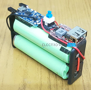
In this DIY project, I will show you how to design and build a simple but effective Solar Battery Charger for 18650 batteries. Using this project, you can charge two 18650 Li-Ion batteries directly from solar without any wall adapter.

Introduction
The need for sustainable living has led to the increased usage of renewable energy. Keeping aside the efficiency numbers, Solar Energy is one of the convenient alternatives (when compared to other renewable energy sources such as wind) to the grid supply.
Now-a-days, large Solar Farms are being setup in acres of barren lands in many countries. But small-scale solar plants like on independent building rooftops and near small home communities are also becoming popular.
The setup of a Solar Power Plant. whether large or small, is fairly simple. Setup an array of Solar Panels on rooftop, connect them to a Solar Charge Controller and charge the batteries. From the batteries, you can run any mains appliances using appropriate inverters.
As a beginner’s solar project, I have designed a very simple Solar Battery Charger to charge 18650 Li-Ion batteries. Using these batteries, you can charge your mobile phones, tablets or use the batteries in LED Lamps, emergency lights etc.
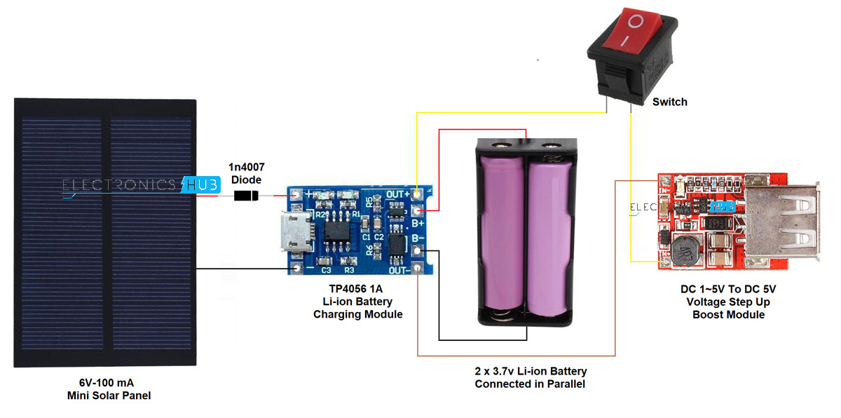
Circuit Diagram
Let us dive into the project by taking a look at the circuit diagram or rather the connection diagram of this DIY Solar Battery Charger for 18650. All the components, which I will list out in the next section, are very easy to acquire and are easily available in local electronics stores (you can get them online as well).
Components Required
- 6V – 100mA Mini Solar Panel
- 2 x 18650 Li-Ion Batteries
- 18650 Battery Holders
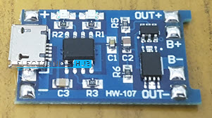
- TP4056 Li-Ion Battery Charger Module with protection
- 1V to 5V Input to 5V Output Step-up Converter (Boost Converter)
- 1N4007 PN Junction Diode
- Switch (Push to ON and Push to OFF)
- Connecting Wires
For more information on TP4056 Li-Ion Battery Charger Module, read “TP4056 Lithium Ion Battery Charger“.
How to Setup DIY Solar Battery Charger for 18650?
First, I will explain the connections and the step by step setup of the Solar Battery Charger for 18650. Then we will understand the principle of operation.
Coming to the connections, the Mini Solar Panel has two wires coming from it. One is Red, which is the positive wire and the other is black (or brown in my case), which is the negative wire.
Now, take the TP4056 Li-Ion Battery Charger Module with battery protection. At the input side, it has two connections named IN+ and IN-. Take the Red wire from the solar panel and connect it to the anode of 1N4007 Diode.
Connect the cathode of the diode to the IN+ terminal of the TP4056 Module and directly connect the black wire of the solar panel to the IN- terminal of TP4056. This completes the input section.
On the output side of the TP4056, there are four connections named B+, B-, OUT+ and OUT-. Take two 18650 Li-Ion batteries with holders and connect them in parallel i.e. both positive terminals of the batteries are common and both negative terminals are common.
Connect the common positive terminal of the batteries to B+ of TP4056. You may have to solder the wires on to the Li-Ion Charger board. Similarly, connect the common negative terminal of the batteries to the B- of TP4056.
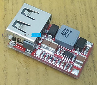
The final step of the constriction is to connect the output of the TP4056 to the 5V Boost Converter Module. The Step-up converter module has two input terminals named IN+ and IN-. Connect the OUT+ of TP4056 to IN+ of Boost Converter module and OUT- to IN- respectively.
You can use a switch between TP4056 and Boost converter so that you can turn ON or OFF the output. I have glued the entire setup on to the battery holder case with a switch in the center and the USB port on the edge.
Principle of DIY Solar Battery Charger for 18650
The solar panel used in this project is small 6V panel with a small output of 100mA. The output of this solar panel will not be a constant 6V but it might fluctuate between 5V and 7.5V (as per its data sheet).
This voltage is given as input to the TP4056 Li-Ion Battery Charging Module, which in this scenario, acts as a Solar Charge Controller. The input to TP4056 can be in the range of 4V to 8V (which is the range of the output of the solar panel).
TP4056 then charges the battery from the solar power itself. If you only want to charge the batteries, then this is sufficient. But since our project also needs to charge a Mobile Phone, we need to have a 5V output and the output of the 18650 Li-Ion batteries is only 3.7V.

Here comes the Boost Converter to the rescue. The boost converter I have used is a 1V-5V input to 5V output step-up converter i.e. it takes an input anywhere between 1V and 5V and produces a constant 5V output. Also, this boost converter can support a current up to 1A, so the charging of mobile phone will not be that slow.
I have used the project to charge my mobile phone as well as to power up an Arduino board.
The post DIY Solar Battery Charger for 18650 Li-Ion Batteries appeared first on Electronics Hub.
Charging into the future: novel rock salt for use in rechargeable magnesium batteries
Tuesday, 21 May 2019
Strain enables new applications of 2D materials
VLOG – Sewable circuits and kebabs in Berlin
I went to Berlin with Elias Bakken. It’s such a cool city.
We met up with Helen Leigh and Drew Fustini to eat kebabs, see homemade instruments, play artsy video games and learn about sewable circuits:
The sewable circuit I made is a touch sensor circuit. Click here to learn how to make a simple touch sensor.
Have you ever been to Berlin? What’s your favorite thing?
Copyright Build Electronic Circuits
Monday, 20 May 2019
Friday, 17 May 2019
Wearable cooling and heating patch could serve as personal thermostat and save energy
Ultra-clean fabrication platform produces nearly ideal 2D transistors
Heart of next-generation chip-scale atomic clock
Thursday, 16 May 2019
New way to beat the heat in electronics
Washable, wearable battery-like devices could be woven directly into clothes
Tuesday, 14 May 2019
New coating could have big implications for lithium batteries
A new sensor for light, heat and touch
Monday, 13 May 2019
Quantum world-first: Researchers reveal accuracy of two-qubit calculations in silicon
A step for a promising new battery to store clean energy
What is Load Factor? Importance, Calculation and Improvement
In this tutorial, we will learn about Load Factor, what is its importance, a simple example to calculate LoadFactor and also different ways to improve the LoadFactor.
Introduction
Almost everything in the World is somehow dependent on Electric Power. From operating your mobile phone to building an Airbus A380, everything requires electricity. The demand for electricity is always increasing and the need for better and efficient ways to generate electric power is higher than ever before.
Power Plants, whether Hydro or Thermal or Nuclear, generate a large quantity of electricity by converting mechanical energy to electrical energy. Irrespective of the method used for generation, power must be carried from the generating stations to the destination i.e. the consumer.
Due to uncertain demands of power by the consumer, the amount of load on the power station varies from time to time. For example, during summer in India, the demand for electricity increases drastically as everyone tries to turn on their air conditioning units.
But the demand will be less during winter as the air conditioning units will be scarcely used, at least in case of residential users. Regardless of the demand, the power plants must be able to meet the requirements instantly.
Commonly used Terms
Before going into the topic of discussion, the LoadFactor, let us first take a look at some of the commonly used terms and their definition in the world of Power Generation.
Load Curve
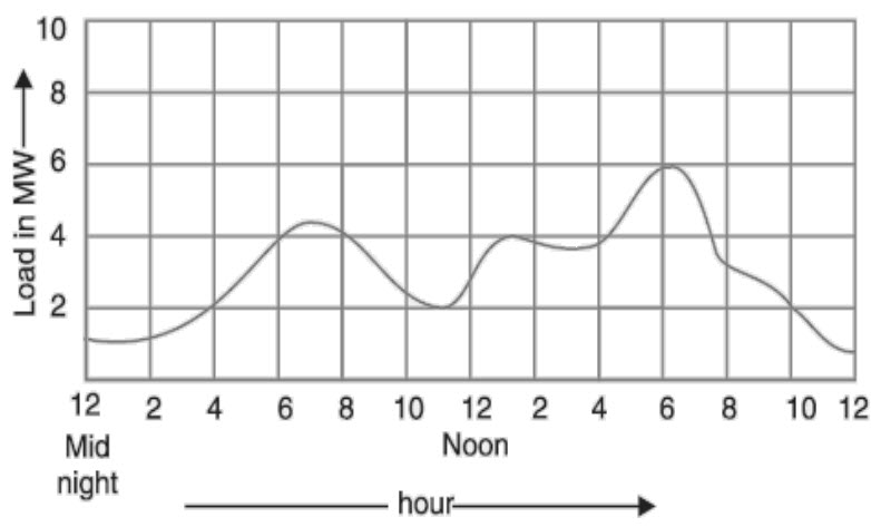
It is a graph representing the load on a power station with reference to hourly time intervals. The Load Curve shows the variations of load on a generating station as a function of time.
The following graph shows a typical load curve of a power station for a period of 24 hours with load in megawatts.
Maximum or Peak Load
It represents the maximum power consumed by the load during a specific period of time. It also represents the maximum power generated by a power station during that period of time (neglecting the transmission losses).
Knowing the Maximum Load is important as it helps in determining the capacity of the power plant.
Average Load
By the name, the Average Load is the average power consumed by the load in a given period, usually, a day or a month. It also represents the average power generated by the power station during the same period (also neglecting transmission losses).
Average Load (kilowatts) = No. of units generated (kWh) / No. of hours (h)
What is Load Factor?
Now coming to Load Factor, it is simply the ratio of Average load to the Maximum or Peak Load during a given period of time. Using LoadFactor, you can easily express the usefulness of a generating station in essence, it determines the efficiency of a power plant.
Load Factor = Average Load / Maximum Load
If we assume that the generating station is in operation for a certain number of hours, then
Load Factor = Energy Generated in a Given Period / (Maximum Load X Hours of Operation)
Depending on the duration of observation, LoadFactor can be calculated on Daily, Monthly or Yearly basis. It is important to observe that the value of LoadFactor will always be less than 1.
LoadFactor acts as a useful factor is describing the electricity consumption characteristics over a period of time as it is an expression of how much energy was used in a given time period versus the amount of energy that would have been used if the power is left on during peak demand.
At the consumer side, an improved load factor means that demand is reduced and will essentially decrease the average unit cost of kWh. This means that for large industries and commercial operations, increasing load factor will definitely lead to significant amount of savings.
Why is Load Factor Important?
Before seeing examples of how to calculate load factor, let us understand the importance of load factor. Every power generating station should be able to meet the peak load demand of electricity at any given time.
Having a higher load factor is desirable and a low load factor means that the electricity usage is inefficient compared to if you were controlling your peak demand. As the load factor represents the actual energy usage versus the peak demand, consumers can use the same amount of electricity from one month to the next and still reduce the average cost per unit (kWh) by reducing the peak demand.
For example, by comparing two months’ electricity usage and assuming they are same, with a 25% LoadFactor in summer will have an average cost per unit of 13 cents while having a 75% load factor in winter will have an average cost per unit of 7 cents.
Calculating Load Factor
Mathematically, Daily Load factor is given by
Daily LoadFactor = Total kWh in 24 hours / (Peak Load in kW X 24 Hours)
Similarly, Monthly and Yearly LoadFactors can be calculated.
For example, the monthly consumption is 48000 kWh and peak demand is 100 kW, then monthly LoadFactor is calculated as follows:
LoadFactor = 36000kWh / (100 kW X 30 X 24h) = 0.5 or 50%
In this example, the 50 % LoadFactor indicates that the monthly consumption was 50% of the total energy available for use at peak demand of 100 kW.
How can we improve Load Factor?
As mentioned earlier, having a higher lower LoadFactor is always desirable. For any consumer, commercial or industrial, lowering its peak demand will be first step in improving the load factor and as a result, reducing the electricity bill amount.
For example, assume an industry with 10 loads or machines. Instead running all the loads at the same time, if certain number of loads are operated in specific time periods, the peak demand would be reduced.
Another way to improve LoadFactor is to analyze the previous electricity bills and identify the periods of peak demand, like summer for example. Make necessary changes so that all the high wattage cooling equipment are not running simultaneously but are scheduled for efficient distribution of peak usage.
The post What is Load Factor? Importance, Calculation and Improvement appeared first on Electronics Hub.
Sunday, 12 May 2019
2D insulators with ferromagnetism are rare; researchers just identified a new one
Thursday, 9 May 2019
Marcus regime in organic devices: Interfacial charge transfer mechanism verified
Substrate defects key to growth of 2D materials
Wednesday, 8 May 2019
Development of 'transparent and flexible battery' for power generation and storage at once
Development of graphene with enhanced speed of high frequency signal transmission
A Simple DIY Universal Remote using Arduino
In this project, we will see how to design a simple DIY Universal Remote using Arduino. Using this remote application, you can control various electronic appliances like T.V., A.C., DVD Players, etc.
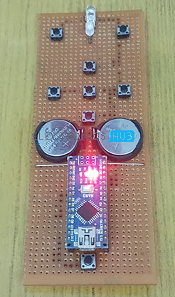
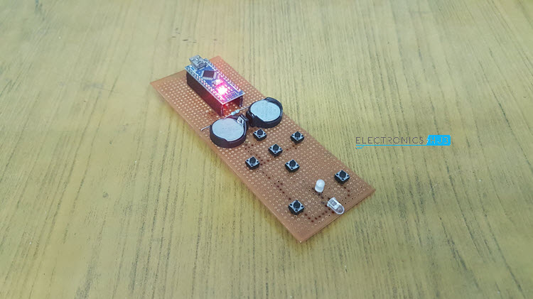
I have implemented the Universal Remote using Arduino Nano and places it on a small perf board along with all the buttons, power supply etc. The final build looks something like this.
Introduction
An IR Remote control is a line of sight based wireless communication device that works in tandem with an IR Receiver. You can find IR Remote controls and corresponding IR Receivers in almost all major electronic appliances like televisions, air conditioners, TV boxes, audio players and many more.
The main problem with this setup is that each device has its own IR Remote control and the more the number of appliances you have, the larger the pile of remote controls.
What if you have a single remote control that can control, if not all then majority of your electrical appliances? This concept is known as Universal Remote Control and it is already existing in the market.
Bringing the same concept to makers and hobbyists, a DIY Universal Remote using Arduino is developed in this project. The reason for building your own Universal Remote using Arduino can be as simple as the satisfaction of building a practical application with your own hands or can be to bypass the cost of an already existing universal remote control from the market.
Principle behind Universal Remote using Arduino
The main principle behind the implementation of an Arduino based Universal Remote Control is very simple. First, using an existing remote control of any appliance like TV for example, the IR Signals are decoded.
These decided signals are then used in the final application to emit the corresponding infrared signals using an IR Emitter LED.
Decoding the IR Signals using Arduino
The first logical step is to decode all the infrared signals from the existing remote controls. I have a Sony TV and a Voltas AC. Using these two remote controls, I have decoded the basic buttons like Power, Volume Up, Volume Down, Previous, Next, Source for the TV and Power, Temperature Up, Temperature Down, Swing, Fan, Turbo for the AC.
Before proceeding with this, I recommend you to go through this simple project called “Arduino IR Receiver Tutorial”, where I have discussed all the important aspects to setup an IR Receiver with Arduino and decode the signals.
Circuit
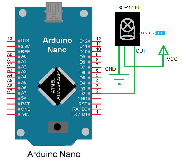
For now, the circuit diagram for decoding the TV and AC Remote keys is shown below, where I have used Arduino Nano along with TSOP1740 IR Receiver.
Code
The code for decoding IR Signals is given below.
All the decoded signals will appear on the serial window. Make a note of all the decoded values.
NOTE: A special library called “IRremote” is used in this project. You can directly install it using Arduino IDE’s Library manager and search for IRremote by shirriff or download the zip file for this GitHub page.
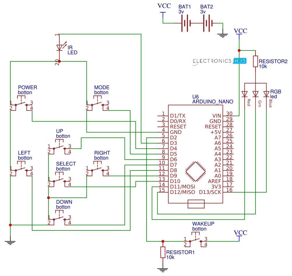
Circuit of Universal Remote using Arduino
Now that we have decoded all the necessary signals from the original remotes, we can now proceed with the actual build of the Universal Remote using Arduino. The circuit diagram is shown below.
Components
- Arduino Nano
- IR LED
- Push Buttons x 8
- CR2032 Battery x 2
- CR2032 Battery Holder x 2
- RGB LED x 1
- 10KΩ Resistor x 2
- Connecting Wires
- Perf board
- Female Header strips (for Arduino Nano)
Circuit Design
First, an IR Led is connected to Digital IO pin 3. Then the buttons are connected as follows:
| Button | Arduino Digital IO Pin |
| Power | 4 |
| Mode | 5 |
| Up | 6 |
| Down | 7 |
| Left | 8 |
| Right | 9 |
| Select | 10 |
Additionally, there is a Wakeup button connected to Digital IO pin 2. Digital IO pin is pulled down using a 10KΩ Resistor, while all the other button pins are pulled up internally. The other ends of all the buttons (except Wakeup button) are connected GND. The other end of the Wakeup button is connected to VCC.

An RGB LED is used to indicate the appliance selected. The RGB LED used here has a common anode terminal, which is connected to VCC through a 10KΩ Resistor. The R, G and B ends of the LED are connected to pins 11, 12 and 13 respectively.
The entire system is powered by a couple of CR2032 3V Lithium cells in series.
Code
Following is the code for the application Universal Remote using Arduino. From the previously collected values, place the corresponding values in the appropriate arrays provided for TC and AC in the code.
These arrays are named tv_onoff[], tv_volup[], tv_voldown[], tv_prev[], tv_next[], tv_source[] for TV related data and ac_onoff[], ac_tempup[], ac_tempdown[], ac_swing[], ac_fan[], ac_turbo[] for AC.
NOTE: An additional library called “LowPower” is used to put the Arduino to sleep after a preset time to save battery. Download this library from this GitHub page.
Working
After inserting the decoded values and uploading the code to Arduino Nano, you can start using the application as a Universal Remote control. First, press the mode button to select the appliance. I have assigned Red LED for TV and Green LED for AC.
So, by pressing the mode button you can select between TV and AC and the Led acts as a visual indicator. Once the mode is set, you can use the remote for that particular device. If no key is pressed for a period of 10 seconds, the LowPower library will kick in and puts the Arduino to sleep.
Use the Wakeup button to wake the Arduino.
Conclusion
A simple but very useful DIY Project called Universal Remote using Arduino Nano is designed here. Using this application, you can control a number of electronic appliances with the help of a single remote control.
The post A Simple DIY Universal Remote using Arduino appeared first on Electronics Hub.
Tuesday, 7 May 2019
New material also reveals new quasiparticles
What are Circuit Breakers? Different Types of Circuit Breakers
In this tutorial, we will learn about one of the very important and extremely useful electrical devices: The Circuit Breakers. We will try to understand what a circuit breaker is, what is the use / importance / function of circuit breakers in power systems, what are the Different Types of Circuit Breakers and also their applications.
Introduction
Circuit Breakers are quite unique devices in the sense that they are mechanical devices connected to electrical system. Since the time when first electrical systems were utilized, there is always a need for a mechanism or a device that can initiate and interrupt the flow of electric current.
In power system, it is often necessary to switch on or off various electrical devices and circuits like generating plants, transmission line, distribution systems, etc. either in normal operating conditions or under abnormal situations. Originally, this task is performed by a switch and a fuse connected in series with the electrical circuit.
The main disadvantage of such a setup is that if a fuse is blown, it is often time consuming to replace one and restore the power supply. The other and main disadvantage is that a fuse cannot interrupt heavy fault currents.
These limitations restricted the usage of switch and fuse combination to small voltage and small capacity circuits. But in case of high voltage and large current system, a more dependable way than using a switch and fuse is desired.
This is achieved with the help of Circuit Breakers.
What are Circuit Breakers?
Circuit Breakers are mechanical switching devices that can make, carry or break a circuit either manually or automatically under normal and abnormal circuit conditions. Under normal conditions, a circuit breaker can make, carry or break currents and under abnormal conditions, it can make or carry for a specific time and break the currents.
The characteristics of a Circuit Breaker are as follows:
- It can make or break a circuit under normal operating conditions either manually or using a remote control.
- Under abnormal or fault conditions, it can break the circuit automatically.
- It can make the circuit under fault conditions either manually or using a remote control.
These characteristics of a Circuit Breaker makes it a very useful device for switching and protection in a power system.
Principle of Operation of Circuit Breakers
The main duty of a Circuit Breaker is to switch ON and OFF the electrical circuits during normal or abnormal operating conditions, once or several times repeatedly. The operating principle of a circuit breaker is very simple.
A typical circuit breaker consists of a fixed and a moving contact called Electrodes. These contacts are closed under normal circuit operating conditions.
If the system becomes faulty, the contacts will open automatically and alternatively, these contacts can also be opened manually whenever desired (for example, during maintenance).
Under faulty system conditions, a simple mechanism will pull the moving contacts away as a result of trip coil getting energized and essentially opening the circuit.
An important phenomenon that occurs during the opening of the contacts is the Arc Phenomenon. If a fault is detected on any part of the system, the contacts of the circuit breaker are separated and during this process, an arc is struck between them. Until the arc discharges, the current in the circuit continues to flow.
The arc not only delays the circuit interruption but also produces a significant amount of heat that could potentially damage the circuit breaker itself or the entire system. Hence, one of the main challenges in circuit breakers is to extinguish the arc as quickly as possible.
Arc Phenomenon in Circuit Breakers
During faulty conditions like a short circuit, for example, a significantly large amount of current flows through the contacts of the circuit breaker before the protective mechanism kicks in and opens the contacts.
The instant when the contacts start to open, the contact area is suddenly reduced and the current density increases due to the large short circuit current. This leads to a rise in temperature and the heat produced is sufficient to ionize the medium (air or oil). The ionized medium acts as a conductor and an arc is struck between the contacts.
This arc provides a low resistance path between the contacts (even though they are open) and the large faulty current continues to flow as long as the arc exists an it defeats the purpose of the circuit breaker.
Reasons for Arc
Before understanding the methods to extinguish arcs, let us try to analyze the factors responsible for the maintaining the arc between the contacts of the circuit breaker.
The reasons can be confined to the following two:
- Potential Difference between the contacts
- Ionized particles between the contacts
The potential difference between the contacts is sufficient for the arc to exist as the separation between the contacts is less. Also, the ionized medium i.e. ionized air or oil have a tendency to maintain the arc.
Different Methods of Arc Extinction
Basically, there are two ways in which you can extinguish the arc between the contacts of a circuit breaker. They are:
- High Resistance Method
- Low Resistance Method
High Resistance Method
In the High Resistance method, the resistance of the arc is increased so that the current will become insignificant to maintain the arc. There are several ways in which you can implement the High Resistance Method.
Some ways to increase the resistance of the arc are:
- Increasing the arc length
- Cooling the arc
- Reducing the area of cross section of the arc
- Splitting the arc
This method is usually implemented in DC Circuit breakers and Low Capacity AC Circuits as it produces enormous amount of heat during the arc extinction.
Low Resistance Method
In the low resistance method, as the name suggests, the resistance of the arc maintained low until the current becomes zero and the arc extinguishes naturally. Hence, this method is also known as Current Zero Method.
The low resistance method is often implemented in high power AC circuit breakers as this method prevents restriking of the arc even when the voltage across the contacts rises.
Another important factor to consider is the ionization of the medium and the tendency of ionized particles to maintain the arc. If the medium between the contacts is deionized, as quickly as possible, the possibility of restriking can be reduced significantly.
Deionization of the medium can be achieved by the following ways:
- Increasing the gap between the contacts
- Increasing the pressure
- Cooling the arc
- Gas Blast effect
Classification of Circuit Breakers
There are several ways of classifying different circuit breakers. Some of the common criteria used for classification of circuit breakers are:
- Intended Voltage Applications
- Location of the installation
- Design Characteristics
- Method and medium used for current interruption (Arc Extinction)
Even though there are several ways to classify circuit breakers, the classification based on the medium and method of current interruption is most general and significant in the industry as well. For now, we will briefly about all these classifications and in the later sections, we will discuss the main classification (i.e. based on method of arc extinction) more thoroughly.
Based on Voltage Class
The first logical classification of circuit breakers is based on the operating voltage intended for the circuit breakers to be used. There are two types of circuit breakers based on the voltage level. They are:
- Low Voltage Circuit Breakers, which are intended to be used at voltages up to 1000V.
- High Voltage Circuit Breakers, which are intended to be used at voltages greater than 1000V.
Again, high voltage circuit breakers are further divided into 123kV or above and 72.5kV or below.
Based on Type of Installation
Circuit breakers are also classified based on the location of installation i.e. outdoor or indoor installation. These circuit breakers are usually high voltage circuit breakers. Indoor circuit breakers are designed to be used inside buildings or with special weather resistant enclosures, usually a metal clad switchgear enclosure.
In fact, the main difference between indoor and outdoor circuit breakers is the packaging structures and enclosures while the internal structure like current carrying parts, interrupting mechanism and operation are pretty much the same.
Based on Type of External Design
The classification of circuit breakers is also done based on the physical structural design and it is usually done in two ways. They are:
- Dead Tank Type Circuit Breakers
- Live Tank Type Circuit Breakers
In Dead Tank Type Circuit Breakers, the switching device is placed in a vessel at ground potential and it is surrounded by interrupters and insulating medium. One the other hand, in a Live Tank Type Circuit Breaker, the vessel containing the interrupters and insulating medium is at higher potential than ground.
Dead Tank Circuit Breakers are more common in the US while Live Tank Circuit Breakers are frequently used in Europe and Asia.
Based on Type of Interrupting Medium
The most significant and important classification of circuit breakers is based on the interrupting medium and arc extinction method. In fact, the current interrupting medium and the arc extinction method have become the main factors in designing the circuit breakers and also, they dictated the overall design parameters.
Originally, oil and air served as the interrupting medium and continue to be still used even after almost a century since their first implementation.
There are two newer techniques, one involving vacuum and the other one based on Sulfurhexafluoride (SF6) gas as the interrupting medium. These two dominate today’s circuit breaker industry but oil and air circuit breakers are also still in service.
Different Types of Circuit Breakers
Since the general and most common way of classification of circuit breakers is based on medium used for arc extinction, we will see different types of circuit breakers based on the same.
Usually, the medium used for extinction of arc is air, oil, Sulfurhexafluoride gas or vacuum. Hence, the different types of circuit breakers based on these media are:
- Air Magnetic Circuit Breakers
- Air Blast Circuit Breakers
- Oil Circuit Breakers
- Sulfurhexafluoride (SF6) Circuit Breakers
- Vacuum Circuit Breakers
Each type has its advantages and disadvantages and we will take a look as all these different types of circuit breakers in detail.
Air Magnetic Circuit Breakers
The first circuit breaker is the Air Magnetic Circuit Breaker. It is also called as Arc Chute Circuit Breaker. Usually, it consists of a number of plates between the contacts and are made up of either metallic or insulated materials.
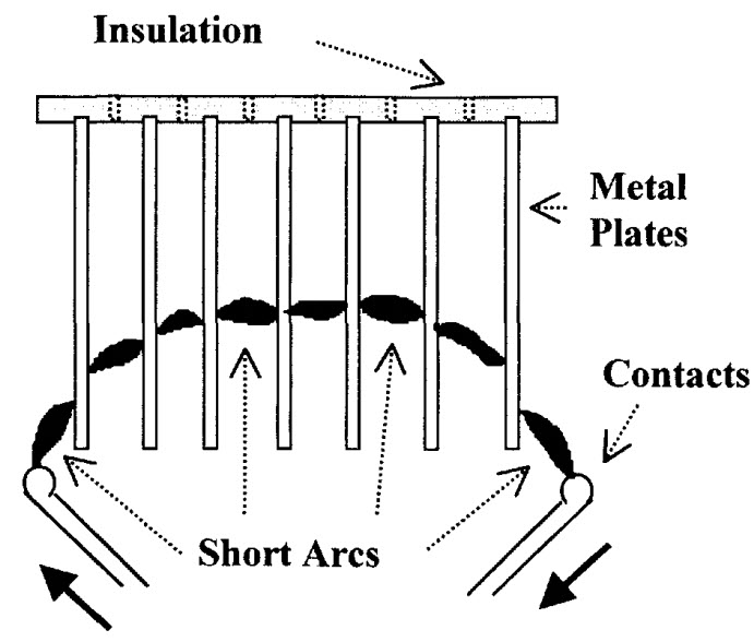
When the arc is struck, it comes in contact with the series of metal plates. As a result, the main arc is divided into a number of smaller arcs that across the plates and the voltage drop is usually 30 to 40 volts. In this type of circuit breaker, the plates are usually metallic.
Another type of arc chute circuit breaker is based on a magnetic low-out assist. This type usually uses insulated arcing plates and are made of ceramic.
In this type, the arc is first made to travel between the insulating plates to elongate the arc. Then the arc is cooled by diffusion. When the circuit breaker begins to open and the arc is initiated, the separation between the contacts is increased. A coil, which is not part of the main conducting circuit, comes into contact with the current.
The magnetic field created by this coil will exert a force on the arc and as a result, the arc tends to move deeper into the chute.
Air Blast Circuit Breakers
The second ‘air’ based circuit breakers are air blast circuit breakers. In this type, a high-pressure air-blast is used as arc extinguishing medium. In case of a fault, the air-blast, controlled by a blast valve, will open the contacts and also cools the arc.
The arc and the arching products are swept into the atmosphere, which rapidly increases the dielectric strength of the medium. As a result, the restriking of arc is prevented. The arc is extinguished consequently and the flow of current is completely interrupted.
There are three types of air blast circuit breakers based on the direction of the air-blast in relation to the arc. They are:
- Axial Blast Type
- Cross Blast Type
- Radial Blast Type
In axial-blast circuit breakers, the air-blast flows in the same direction as the arc. The high-pressure air-blast will push the moving contact away, opening the circuit and also pushes the arc along with it.
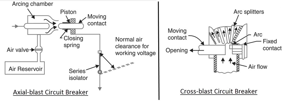
The air-blast in cross-blast type circuit breakers is perpendicular to the arc path and in radial-blast type circuit breakers, it is directed radially.
Advantages
- Risk of fire is eliminated.
- Arcing products are completely removed by the air-blast.
- Significantly faster increase in dielectric strength. Hence, the contact gap can be less, resulting in smaller device.
- Arcing time is very small and the arc energy is also small. Suitable for frequent operations.
- Air-blast is independent to the interrupting current.
Disadvantages
- Arc extinguishing properties of air are inferior.
- Sensitive to variations in restricting voltage.
- Air-blast compressor needs to be maintained.
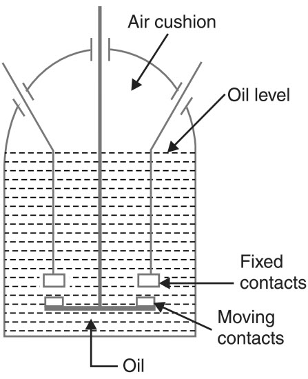
Oil Circuit Breakers
In Oil Circuit Breakers, an insulating oil is used as the arc extinguishing medium. As the contacts are opened in oil, when the arc strikes, the surrounding oil is evaporated as hydrogen gas.
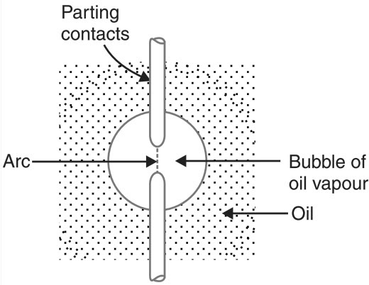
The hydrogen gas bubble will surround the arc region. Hydrogen gas, due to its high thermal conductivity, cools the arc and also deionizes the medium. Also, the gas causes turbulence in the surrounding oil and all the arcing products are pushed away from the arc.
There are two types of oil circuit breakers. They are:
- Bulk Oil Circuit Breakers
- Low Oil Circuit Breakers
As the name suggests, bulk oil circuit breakers use a significantly large quantity of oil. Further, bulk oil circuit breakers are again divided into two types.
- Plain Break Oil Circuit Breakers
- Arc Control Oil Circuit Breakers
In Plain Break Oil Circuit Breakers, the contacts are separated in the oil tank and the system for arc control is to increase the separation of the contacts. When a critical gap between the contacts is reached, the arc extinction occurs.
The lack of control over the arc in plain break oil circuit breakers is overcome in Arc Control Oil Circuit Breakers. The arc control is implemented in two ways known as:
- Self-blast Oil Circuit Breakers
- Forced-blast Oil Circuit Breakers
In self-blast type breakers, an insulating rigid pressure chamber is used with the contacts and the gases released during arcing are confined to this chamber or pot. The high pressure developed in the small chamber will force the oil as gas to go through the arc and subsequently extinguishing it.
There are three type or designs of pressure pots in Self-blast Oil Circuit Breakers. They are:
- Plain Explosion Pot
- Cross Jet Explosion Pot
- Self-compensated Explosion Pot
Coming to Forced-blast Oil Circuit Breakers, a piston cylinder is used to create the necessary oil pressure in contrast to Self-blast Oil Circuit Breakers, where the pressure is developed by the arc itself.
In all the Bulk Oil Circuit Breakers mentioned above, the oil has two jobs. One is to act as an arc extinguishing medium and the other is to insulate live circuit from earth. Only a small percentage (10% or less) is actually used for arc extinction and the majority of the oil is used for insulating purpose.
In Low Oil Circuit Breakers, oil is used for arc extinction and a solid material like porcelain and paper are used for insulation.
Advantages
- Oil has excellent cooling property and the arc energy converts the oil into gas.
- Acts as insulator between live wires and earth.
Disadvantages
- Oil is inflammable and is a fire hazard.
- Arcing products cannot escape and remain in the oil.
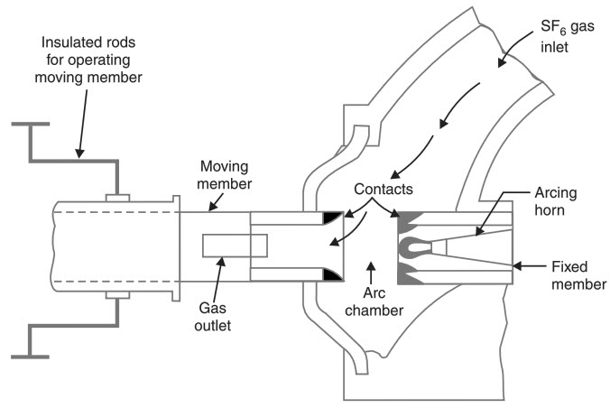
Sulfurhexafluoride (SF6) Circuit Breakers
In Sulfur Hexafluoride circuit breakers, Sulfur Hexafluoride with chemical formula SF6, is used as the arc extinguishing medium.
The Sulfurhexafluoride gas is electro-negative in nature i.e. it attracts free electrons. When the circuit contacts are opened, a high pressure Sulfurhexafluoride gas flows through the chamber as the arc strikes.
Free electrons produced during the arcing are quickly absorbed by the SF6 gas resulting in immobile negative ions. As the arc loses its conducting electrons, the insulating strength of the surrounding medium is quickly increased and the arc completely extinguishes.
Following image shows a simplified construction of SF6 Circuit Breaker. Both the fixed and moving contacts are placed in arc chamber, which contains Sulfurhexafluoride gas. When the contacts open, a high pressure SF6 gas from a reservoir will flow through the chamber’s inlet.
Advantages
- Superior arc extinguishing property.
- Can interrupt larger currents as the dielectric strength of SF6 gas is almost 3 times greater than air.
- Noise free operation and no exhaust into atmosphere.
- Moisture free operation as the gas filled chamber keeps in interior dry.
- Very low maintenance and requires minimum equipment.
- Suitable for hazardous and hostile conditions like coal mines as the breakers are enclosed and sealed.
Disadvantages
- Sulfurhexafluoride gas is very costly.
- SF6 has to be reconditioned after every operation.
- This high pressure Sulfurhexafluoride gas will absorb all the conducting free electrons and as a result causes the extinction of the arc.
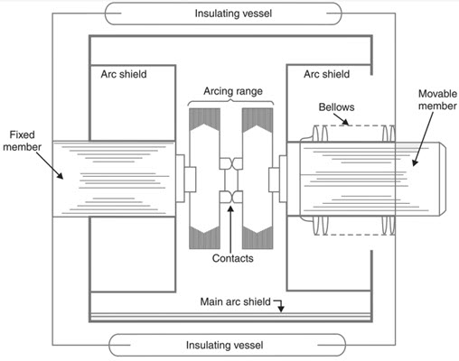
Vacuum Circuit Breakers
In vacuum circuit breakers or VCB, the arc extinguishing medium is, well Vacuum. It offers superior arc extinguishing properties than other medium as it has the highest insulating strength.
When the contacts of the circuit breaker in vacuum are opened, an arc is formed due to ionization of the metal vapours of the contacts. But the arc is quickly extinguished as the vapours rapidly condense.
A typical vacuum circuit breaker is shown in the following image. It consists of a moving contact and a fixed contact and also an arc shield mounted in a vacuum chamber. The outer insulating body is usually made up of glass or ceramic.
Advantages
- No fire hazards.
- Compact, very reliable and have very long life.
- No gas is generated during or after operation.
- No or very little maintenance.
- VCB can interrupt any fault current.
- Can withstand lightning strikes.
- Low arc energy is released.
The post What are Circuit Breakers? Different Types of Circuit Breakers appeared first on Electronics Hub.