Monday, 31 July 2023
Way cool: 'freeze ray' technology
Arduino Blink LED – Getting Started Tutorial
The Arduino blink LED circuit is a simple circuit that works great for starting to learn Arduino. Both the code and the connections are straightforward so that you can understand it with little to no background.
In this quickstart guide, you’ll learn how to connect an LED to an Arduino board and make it blink.
Parts Needed
- Arduino Uno
- Breadboard (and some breadboard wires)
- Light-Emitting Diode (LED) (Most LEDs will work)
- Resistor (220 Ω)
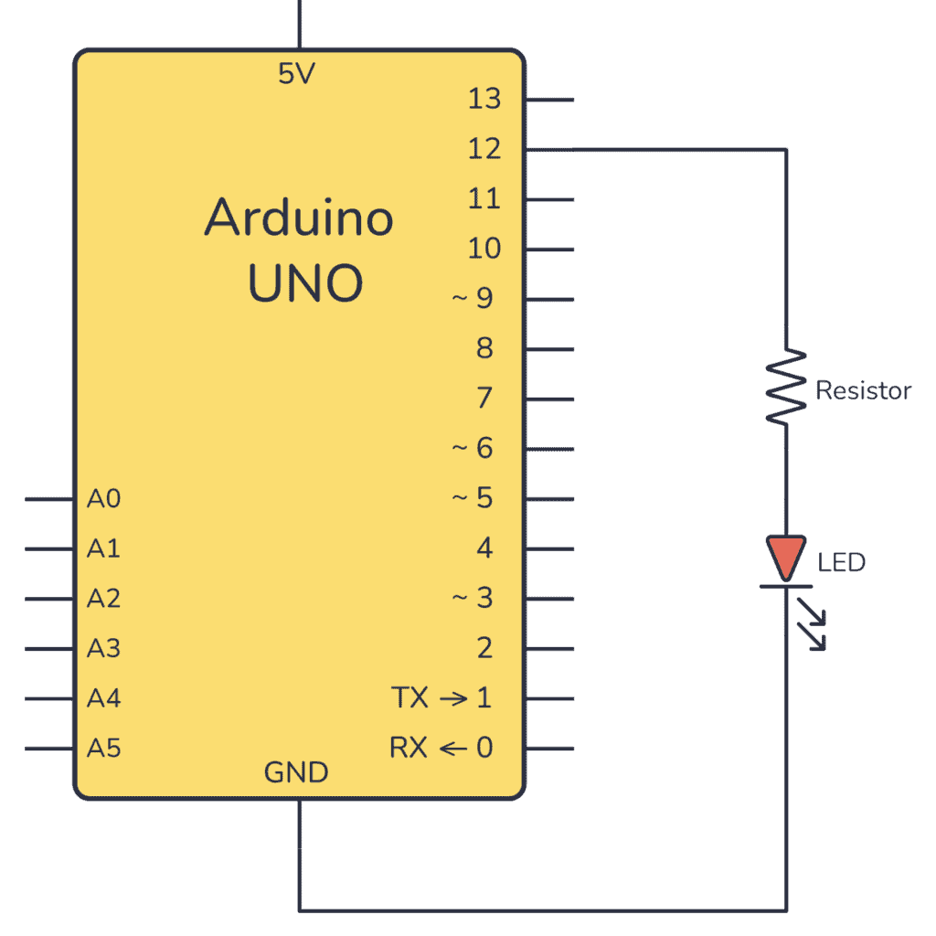
Arduino Blink LED Circuit
To connect an LED to an Arduino, you need a resistor in series with the LED. This is to limit how much current the LED pulls out of the Arduino pin. The value isn’t crucial but should be between 220 Ω and 1000 Ω.
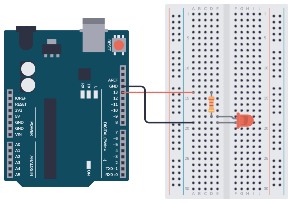
Connecting On a Breadboard
Here’s how you can connect the LED and the resistor to the Arduino by using a breadboard and a couple of cables:
Arduino Blink LED Code
All Arduino code is structured around the two main functions setup() and loop().
The setup() function runs only once when the Arduino board starts up. It is used for initializing variables, pins, and other settings.
The loop() function runs repeatedly after the setup() function has been executed. Whatever code is inside this function will be executed over and over again in an endless loop until the Arduino is powered off or reset.
Inside setup(), you need to configure pin 13 as an output.
Inside loop(), you need to set pin 13 HIGH, wait for a second, turn it low, then wait for another second.
Check out the complete code:
// The setup function that runs one time at startup
void setup() {
  pinMode(13, OUTPUT);     // Initialize digital pin 13 as an output.
}

// The main loop that continues forever
void loop() {
  digitalWrite(13, HIGH);  // turn the LED on (HIGH is the voltage level)
  delay(1000);             // wait for a second
  digitalWrite(13, LOW);   // turn the LED off by making the voltage LOW
  delay(1000);             // wait for a second
}
How the code works
Inside the setup() function there is only one line: pinMode(13, OUTPUT); This line sets pin 13 as an output so that we can use it to turn the LED on or off.
Inside the loop() function there are four lines:
digitalWrite(13, HIGH);This line turns on the LED connected to pin 13.HIGHsets the voltage of the pin to the logic HIGH level (usually 5V on most Arduino boards), which turns on the LED.delay(1000);This line adds a delay of 1000 milliseconds (1 second). It means the LED will remain on for one second before moving on to the next line of code.digitalWrite(13, LOW);This line turns off the LED by setting the voltage level of pin 13 to LOW (0V).delay(1000);This line adds another 1-second delay. So after the LED is turned off, the program waits for one second.
After this, the program goes back to the beginning of the loop() function where it turns the LED on again, and the process repeats.
This code results in a LED (connected to pin 13) blinking on and off repeatedly, with each state (on and off) lasting for one second.
Copyright Build Electronic Circuits
Sunday, 30 July 2023
Engineering team uses diamond microparticles to create high security anti-counterfeit labels
Saturday, 29 July 2023
This 3D printed gripper doesn't need electronics to function
Tuesday, 25 July 2023
How Capacitors Work – A Tutorial For Hobbyists
A capacitor is a basic electronic component that works like a tiny rechargeable battery with very low capacity. Capacitors are used to create oscillators, time delays, add a power boost, and much more.
Like most components, the easiest way to understand how a capacitor works is to see with your own eyes what it does in a circuit.
When I started learning electronics as a teenager, this was the first component I learned about. The way my father explained it to me made it easy to understand even though I had no understanding of the basics of electronics.
In this guide, I’ll show you how a capacitor works so that you’ll be able to understand what it does in circuits, and how you can use it in your own projects.
Covered in this guide:
- What Is a Capacitor?
- How Capacitors Work
- Charging a Capacitor
- Types of Capacitors
- What Are Capacitors Used For?
- Typical Capacitor Values
What Is a Capacitor?
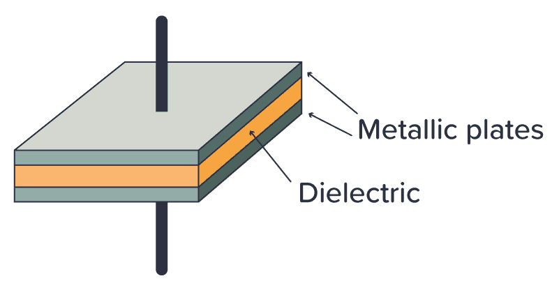
A capacitor is made up of two metallic plates with a dielectric material (a material that does not conduct electricity) in between the plates. And there’s actually no more magic to it. It’s that simple and you can even make your own capacitor by using two sheets of aluminum foil with a piece of paper in between.
When you apply a voltage across the two plates, a current flows as the voltage tries to push electrons through the capacitor. But electrons can’t flow through the dielectric between the plates, so instead the electrons will build up on one plate and leave the other plate.
Eventually, the side where the electrons gather won’t have room for more electrons, so the current stops flowing. When that happens, the capacitor is fully charged. The amount of electric charge the capacitor can hold is called its capacitance.
Electrons don’t like being crowded together on one plate. They want to go over to the side with fewer electrons. So if you provide a path for the electrons to flow (for example by connecting a resistor between its legs) the electrons will flow back to the other side until there’s an equilibrium of electrons on both sides of the capacitor again.
How Capacitors Work
I like to answer the question of “How does a capacitor work?” by saying that a capacitor works like a tiny rechargeable battery with very low capacity.
But a capacitor is usually charged and discharged in a fraction of a second. So it’s not used for the same purpose as a battery. Instead, it’s used for things like adding a time delay, creating oscillators, and as tiny backup generators for microcontrollers.
Check out the video below to see how the capacitor works:
A Simple Capacitor Circuit
If you want to understand how the capacitor works without reading theory and formulas – then build this circuit:
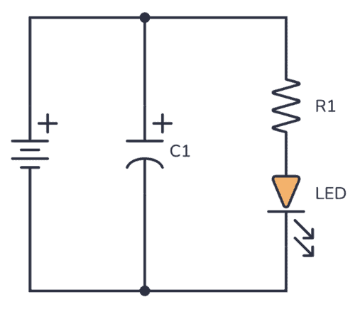
You can use a 9V battery, a standard Light-Emitting Diode (LED), and a 1000 µF capacitor. The resistor value can be around 500-1000 ohms.
Connect the battery, and you should see the LED turn on. Nothing special yet.
But when you disconnect the battery, something interesting happens… The LED stays lit for a few more seconds without being connected to the battery!
This happens because the capacitor is first charged by the battery. When you disconnect the battery, the stored charge in the capacitor flows through the resistor and LED and thereby keeping the LED on for a few more seconds, until the capacitor is discharged.
So the capacitor works similarly to a battery – it can be charged and discharged.
Charging a Capacitor
If you want to get a really good understanding of capacitors and how to use them in your circuits, there are two important things you need to know:
- What happens to the voltage across the capacitor when you charge it?
- What happens to the current through the capacitor when you charge it?
The Voltage Across a Capacitor
If you charge a capacitor from a 9V voltage source, the voltage across the capacitor will eventually become 9V – but not immediately. At the moment when you start charging it, the voltage will start at 0V.
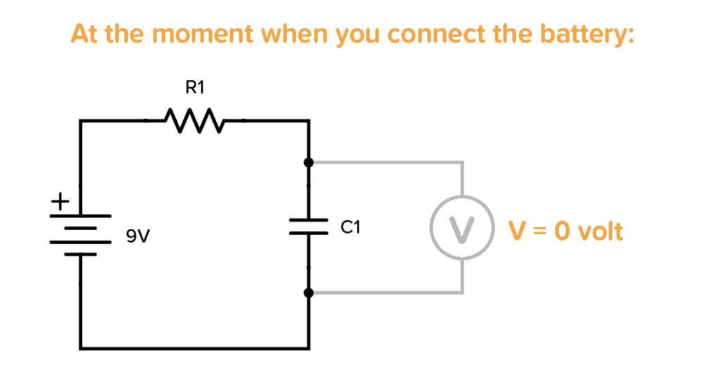
But the voltage increases quickly, so if you try to measure it with a multimeter, you won’t be able to read 0V.
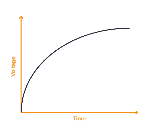
After some time, when it is fully charged, the voltage across it becomes 9V (or whatever voltage you used to charge it):
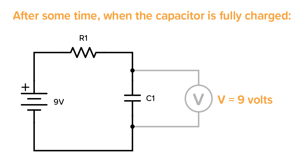
The voltage increases quickly in the beginning, then slowly at the end. The time it takes to charge the capacitor depends on how much current is flowing. In the example above, it would be determined by the resistor R1.
The Current Through a Capacitor
When you start charging a capacitor, the current flows freely without any resistance in the very beginning.
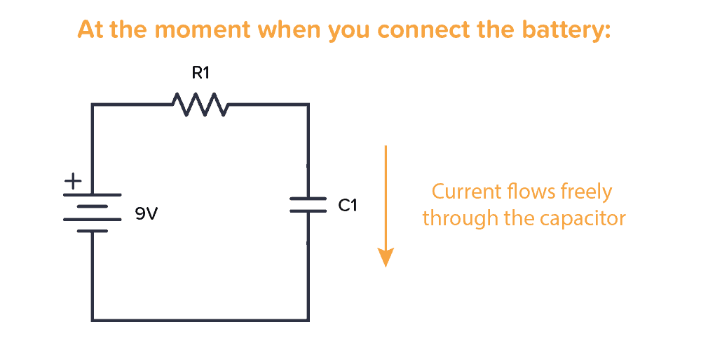
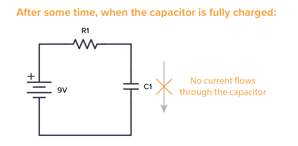
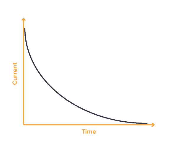
As the capacitor charges, the resistance increases so that less and less current can flow. When the capacitor is fully charged no more current flows through it:
Here’s a simplified graph that shows how the current slows down with charging time:
Types of Capacitors
There are many different capacitor types. But when you start out, the main thing to remember is the difference between a polarized and a non-polarized capacitor.
A polarized capacitor needs to have its positive side connected toward plus, and the other side toward minus. Otherwise, you might destroy it. This is a side-effect of how large-value capacitors are made.
A non-polarized capacitor can be connected either way, it doesn’t matter.


You can recognize one or the other in a schematic diagram by looking at the capacitor symbol. The polarized capacitor will have a plus marking.
Polarized vs Non-Polarized Capacitors
A non-polarized capacitor can be used, even if the schematic for the project you’re building calls for a polarized capacitor. But not necessarily the other way around.
If you need a polarized capacitor, you need something called an electrolytic capacitor. The most common types are Aluminium and Tantalum. Aluminum is the cheapest of the two. But if you need a smaller and more durable capacitor, you should choose the Tantalum type.
If you need a non-polarized capacitor, the most common types are Ceramic and Film.
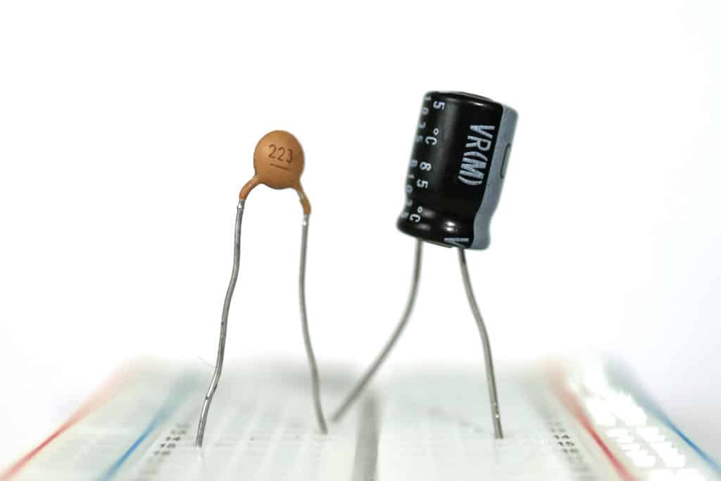
Ceramic capacitors are small and cheap. It’s the most common choice for non-polarized capacitors. But if you have any special requirements like low tolerance, high reliability, or a capacitor that is able to operate under high temperatures, then choose a Film capacitor.
In the photo below you can see a ceramic capacitor on the left and an aluminum electrolytic capacitor on the right:
What Are Capacitors Used For?
Capacitors are used for a lot of things, such as:
- Adding a time delay in a circuit
- Making oscillators (for example to make a light blink)
- Creating audio filters (such as low-pass and high-pass filters)
- Remove ripple in a power supply
- Adding short bursts of energy (for example to power the flash of a camera)
- Stabilizing the voltage supply of a microcontroller
…and much more. I’ll go through a few specific circuit examples below that you can use to improve your understanding of the capacitor.
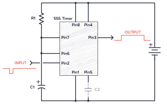
Example 1: Add a Time Delay
In this example, when the input signal goes low, the output from the 555 timer goes HIGH for a certain period of time before going back to LOW. You could for example use it to turn on the lights on your porch for 2 minutes every time an IR sensor detects that there is someone present.
In this circuit, it’s the capacitor C1 that adds the time delay. All the 555 timer does is provide the logic to check the voltage level across the capacitor against a threshold level, then turn the output on or off accordingly.
Example 2: Create an Oscillator (Blinking an LED)
In this blinking LED example circuit, the voltage across the capacitor is interpreted as either a 1 (HIGH) or a 0 (LOW) by the NOT gate.
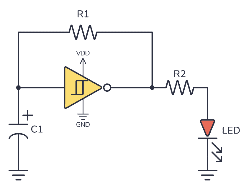
The output becomes the opposite of the input. So if the input is LOW, the output is HIGH. When the output is HIGH, the output voltage will start charging the capacitor so that it eventually also ends up HIGH. But when it does, the output will switch to being LOW. When the output is LOW, it will make the capacitor start discharging so that it eventually also ends up being LOW.
And the process repeats.
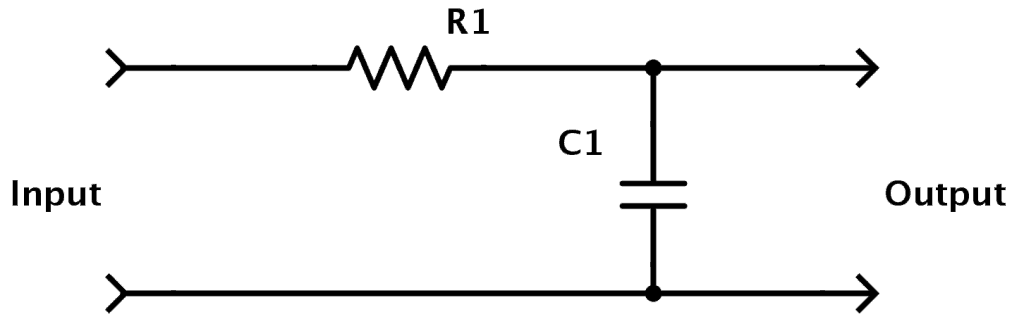
Example 3: Design Audio Filters
You can combine capacitors and resistors to form filters. A filter removes specific frequencies from an audio signal and lets others pass through. For example, if you want to remove high frequencies and let the lower frequencies pass through (e.g. in a sub-woofer), you can build a low-pass filter:
Example 4: Decoupling Capacitors for Microcontrollers
Imagine a typical alarm clock, powered by the electrical outlet on the wall in a house. If the power goes down, most alarm clocks have a backup battery that will take over and power the alarm clock until the power comes back on so that the time is not reset.
Well, in electronic circuits capacitors are used in a similar way:
If you have a circuit with a microcontroller running some code and the supply voltage to the microcontroller drops for only a split second, the microcontroller stops what it is doing and restarts. That can cause all sorts of problems, so you don’t want this.
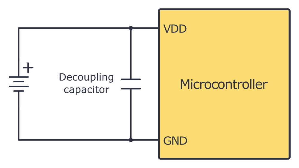
By using a capacitor, the capacitor can supply power for the microcontroller for a short period so that the microcontroller doesn’t restart. This way it will filter out noise on the power line.
A capacitor used for this purpose is called a decoupling capacitor.
Typical Capacitor Values
You have two important values for capacitors; capacitance and voltage rating.
The capacitance value of a capacitor is its “capacity” to store energy. A higher capacitance value means it can store more energy than a lower value. It is given in Farads (F).
The voltage rating is the maximum voltage a capacitor can handle. So if you have a circuit where the voltage across the capacitor can reach 12V, you need a capacitor with a voltage rating of 12V or more. It is recommended to use a capacitor rated for more than 12V so that you have some safety margin.
The capacitance value is given in Farad (F). But 1 F is a very high value. Usually, capacitor values are given as microfarad (µF), nanofarad (nF), or picofarad (pF). In the table below, you can see these values written out:
| Prefixes | Compact Value | Written-Out Value |
|---|---|---|
| 1 F | 100 F | 1 Farad |
| 1 µF | 10-6 F | 0.000001 Farad |
| 1 nF | 10-9 F | 0.000000001 Farad |
| 1 pF | 10-12 F | 0.000000000001 Farad |
If you look closely, you’ll see that for example, 100 nF is the same as 0.1 µF. This is good to remember. Because it’s very common to use both 0.1 µF and 100 nF to describe the same value.
Identifying A Capacitor Value
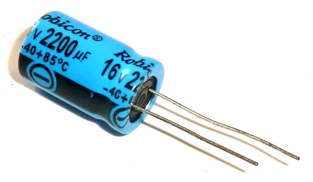
On big aluminum capacitors, the values are usually written out in cleartext. For example, if it says 2200 µF 16V, that’s the capacitance value and the voltage rating.
But often on smaller capacitors, you instead have cryptic numbers. Like 102, 223, or 474. In these cases, the first two numbers make up the base pF value, and the last is the number of zeroes you add after:
102: 10 pF with 2 zeroes after is 1000 pF. Which is the same as 1 nF.
104: 10 pF with 4 zeroes after is 100000 pF. Which is the same as 100 nF. Or 0.1 µF.
223: 22 pF with 3 zeros after is 22000 pF. Which is the same as 22 nF.
474: 47 pF with 4 zeroes after is 470000 pF. Which is the same as 470 nF. Or 0.47 µF.
Learn more about capacitor values, prefixes, standards, and calculations here.
Copyright Build Electronic Circuits
Monday, 24 July 2023
Novel thermal sensor could help drive down the heat
Friday, 21 July 2023
The Insulated Gate Bipolar Transistor (IGBT): A Practical Guide
This is a practical guide to the Insulated Gate Bipolar Transistor, or IGBT. You’ll learn how to use it from a practical standpoint – without going into the physics of what it looks like on the inside. The IGBT is often presented as something complex and advanced. But when you strip away the physics explanation and get down to practice, putting it into a circuit is straightforward.
By the end of this guide, you will be able to use an IGBT and build your first simple circuit with it.
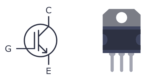
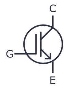
What is an IGBT?
An Insulated Gate Bipolar Transistor (IGBT) is a special type of transistor that can be useful in circuits where there is a lot of current that needs to be switched on and off. It’s a mix between a MOSFET and a BJT transistor.
It has three pins – Collector, Emitter, and Gate. As the name suggests the gate terminal is insulated from the rest, so no current flows into the gate, just like the MOSFET. When you turn it on, current flows between the collector and emitter pins.
The gate voltage controls how much current flows through the emitter-collector terminals. In other words, the input voltage controls the output current. So IGBT is a voltage-controlled transistor.
IGBT vs MOSFET
If you already know how MOSFETs work, you’re good to go, because IGBTs work the same way in a circuit. And the truth is that in most practical cases, you can think of the IGBT as a MOSFET.
The main difference is that the IGBT transistor can handle much higher currents and voltages than the MOSFET transistor.
Depending upon the device, an IGBT can handle currents as high as 500A and up. The gate voltage required to switch on an IGBT is usually around 4-8V.
Types of Insulated Gate Bipolar Transistors
There are two types of IGBT:
- Punch-through IGBT: Allows current to flow from collector to emitter only, not the other direction This type of IGBT is used in DC circuits and is also known as an asymmetrical IGBT.
- Non-punch-through IGBT: Allows for current to flow both ways – from collector to emitter – or from emitter to collector. This type of IGBT is used in AC circuits and it is also known as a symmetric IGBT.
So if you’re building an AC circuit, use the asymmetrical (punch-through) version. And if you’re building a DC circuit, use the symmetrical (non-punch-through) version.
Practical Examples of Using an IGBT in a Circuit
Because it can handle such high currents, IGBTs are typically used in power electronics. You’ll find it in switch mode power supplies, in circuits that drive heavy loads such as electric motors, in air conditioners, refrigerators, and more.
Below are some practical examples using Insulated Gate Bipolar Transistors in a project:
Building a Tesla Coil at Home
Probably one of the coolest Halloween decorations out there is the Tesla Coil! The classic way of building one is by using spark gaps. But an IGBT can be used instead to make a solid-state Tesla coil.
You can build your own Tesla coil by combining an IGBT with standard components like a 555 Timer, a 74HC14, and other basic electronic components.
Repairing an Induction Cooker
When his induction cooker broke, Johannes from Sweden wanted to see if it was possible to repair it himself. He opened his cooker, and after some research, found that the transistors of the cooker had been broken. After ordering spare parts for around $30, his cooker was working perfectly again.
But he didn’t stop there. He went on to add Bluetooth support and is now controlling his cooker from his phone. Read the whole story over at Johannes’ GitHub page.
Controlling an Electric Car with Custom Electronics
New electric cars have big motors that need lots of current. Cars use brushless motors, and they need to be controlled properly. IGBTs are great for this job.
If you’re interested in these types of circuits, I highly recommend checking out etischer’s homemade EV motor controller. He’s even made a full walkthrough of the circuit in video form.
Build Your First IGBT Circuit
Now that you know the basics, it’s good to get some practical experience. It’s time to build your first IGBT-based circuit – a variable voltage supply. You can build this circuit on a breadboard. You will need the following parts:
- An IGBT (such as WG30NC60)
- A 1K resistor
- A 10K potentiometer
- A 12V power supply
- Any output load such as a DC motor, fan, or a bulb
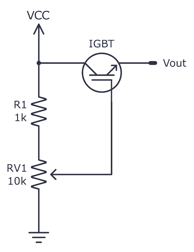
Connect the circuit as shown in the schematic above.
How It Works
When you turn the potentiometer, the voltage across the gate of the IGBT changes. This will increase or decrease the current across the collector-emitter terminal.
To test this, you can connect a DC motor to the output to see it change speed as you turn the 10K pot. Or see the brightness of the bulb change when connected across the output. If you want to use the circuit for high voltages and currents, use a heat sink for the IGBT and solder the components on a PCB with suitable wires.
Copyright Build Electronic Circuits
Friday, 14 July 2023
New superconductors can be built atom by atom
Thursday, 13 July 2023
Researchers develop approach that can enable inexpensive mass manufacturing of micro-LED displays
New material could hold key to reducing energy consumption in computers and electronics
Wednesday, 12 July 2023
Towards crack-resistant nanoparticle-based latex films
How to Build a DC Linear Power Supply
A DC linear power supply is an electric circuit that converts AC voltage to a stable regulated DC voltage – without any switching or digital circuitry. This makes the circuit both simple to understand and easy to build.
In this guide, you will learn how DC linear power supplies work and how to build your own.
What Does a Linear Power Supply Do?
A linear power supply converts AC into DC and gives you a stable DC voltage output. So first, you need to understand the difference between AC and DC voltage:
AC voltage changes its polarity and magnitude periodically, whereas DC voltage is stable and remains constant in polarity.
Here’s a simple comparison between AC and DC voltage signals:
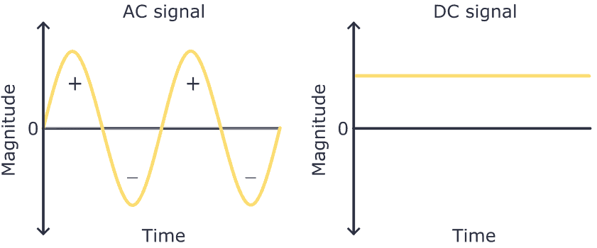
Electrical outlets in your wall provide AC voltage. But most devices, like your phone or laptop, need DC voltage to work.
That’s why chargers or DC wall adapters exist; they convert AC voltage to DC and lower the voltage, allowing you to power up your device from any electrical wall outlet. These wall adapters are small power supplies.
To build a linear power supply, you’ll need the following components:
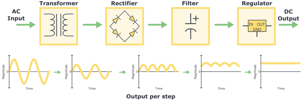
- Transformer: The AC voltage from the wall outlet has a high magnitude, like 110/220 V AC. So the first thing to do is transform it into a signal with a lower magnitude. This is achieved using a component called a transformer.
- Rectifier: Once the AC voltage is transformed, it is then passed through a rectifier. The rectifier converts the AC voltage into pulsating DC voltage by allowing current flow in only one direction and removing the negative portion of the AC waveform.
- Filter: After rectifying, a filter is used to smooth out and minimize the pulsating DC voltage. Typically, due to their ability to store energy, capacitors are used in this kind of filter circuit.
- Regulator: To have a stable DC voltage value output, a voltage regulator is needed. It ensures a constant and stable DC voltage output, compensating for fluctuations in the load or input voltage.
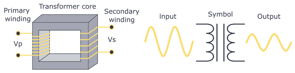
Transformer
A transformer is a component that consists of two coils with wire wound around a magnetic core. When an AC current flows through the primary winding, it creates a changing magnetic field, which induces a current in the secondary winding. The number of wire turns in each winding determines the attenuation or amplification factor. For example, you could convert 110 V AC into 12 V AC by choosing the right transformer.
Take a look at the construction and symbol of a transformer:
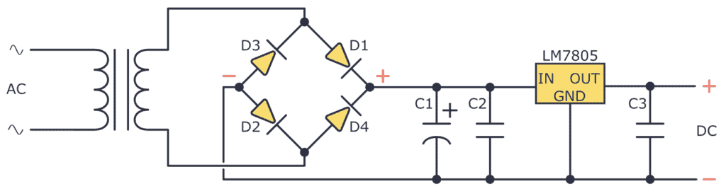
Rectifier
The rectifying step is a key part of converting AC to DC as it eliminates the negative half-cycles of the AC signal. As a rectifier, you can use a diode bridge. Check out the diode bridge circuit and what it does to an AC signal below:
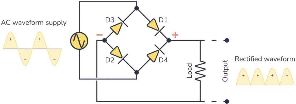
If you want to learn everything about this circuit, check out this article: Rectifier Diode: Guide to Functionality and Circuits
Capacitor filter
Once you get a pulsating DC signal from the rectifier you can smooth it by implementing a capacitor as a filter. To build this filter you just need to connect a capacitor between the positive and negative terminals you get from the diode bridge.
The capacitor will charge as the rectified voltage increases and release its charge as the rectified voltage decreases. Observe this behavior below.
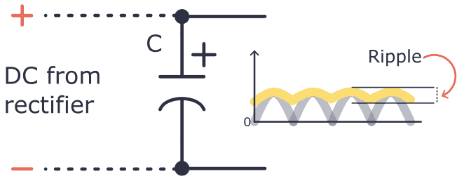
You can see how even if a filter is applied, the AC signal is not 100% steady, it still has some small magnitude variations. This effect is called ripple. The higher the capacitor capacitance, the lower the ripple.
Voltage Regulator
Once you get the DC voltage there are many ways to regulate it to a desired value. For example, you can use a Zener diode, or you could implement a dedicated voltage regulator circuit such as devices from the LM78xx family.
Let’s suppose you want to regulate the voltage that comes after the capacitor filter to 5V, for that using the LM78xx family you’ll need the LM7805.
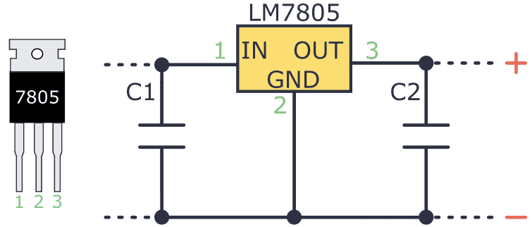
As you can see this voltage regulator is very easy to use. It typically has an input pin (Vin), an output pin (Vout), and a ground pin (GND). The input pin must be attached to the positive terminal of the input voltage to regulate, while the output pin goes to the load. The ground pin must be connected to the circuit’s common ground.
Also, I recommend adding capacitors to the input and output pins to reduce ripple and noise.
Put all this together, and you’ll end up with this circuit:
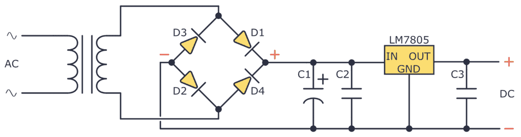
Building a DC Linear Power Supply
Now that you know how a DC linear power supply works, it’s time to see how you can build one!
 Please keep in mind that working with high voltage can be dangerous. Avoiding electrical shocks is one thing, but you also need to use proper wire thickness and spacing to avoid the risk of fire.
Step 1: Wire the Transformer
The first thing to do is wire the transformer. I have 127V AC in my wall outlet, so I used a transformer designed for this. The one I used was a center tap transformer 127 V AC / 18 V AC.
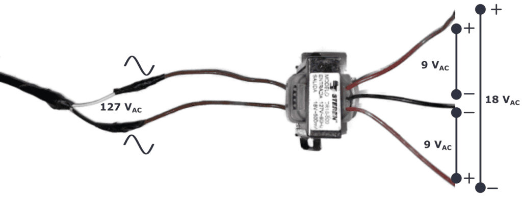
A center tap transformer has a secondary winding with a center tap in the middle. This design allows multiple voltage levels from a single transformer configuration. For example, to get +9V, 0V, and -9V.
For this circuit, I only used one of the 9V AC outputs.
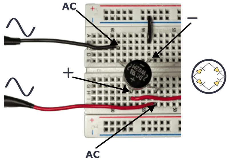
Step 2: Add a Diode Bridge
For the rectifier, I used the diode bridge W02M, which has the necessary diode arrangement within its compact body.
This device has four terminals, two for receiving the AC voltage and two for outputting the pulsating DC signal. See its connection below.
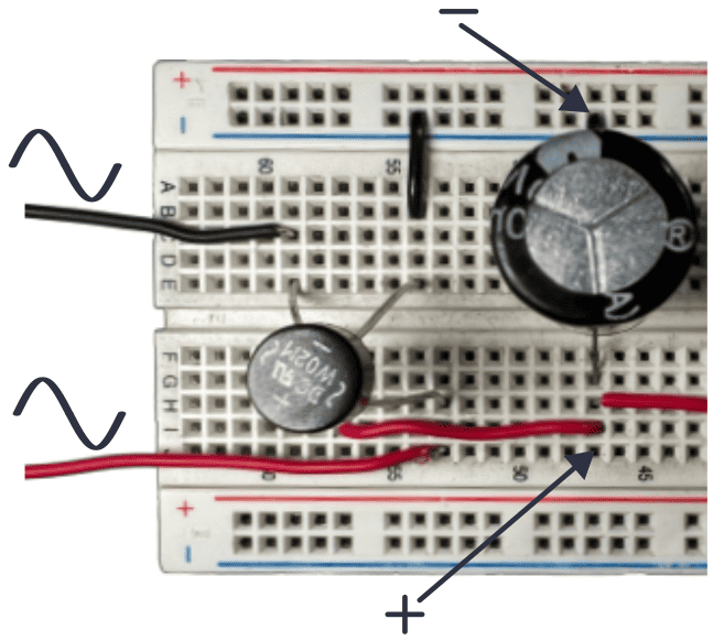
Step 3: Filter the Rectified Voltage With a Capacitor
To smooth out the pulsating DC voltage, you already know you need to use a simple electrolytic capacitor. For this example, I used a 1000 uF capacitor. Check out its wiring:
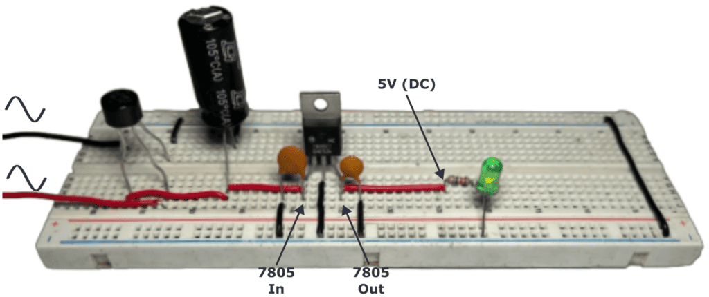
Step 4: Regulate the DC voltage
At this point, the output voltage of the 1000 uF capacitor is 9 V DC. To regulate the voltage to 5 V this example uses the LM7805 regulator.
The LM7805 datasheet recommends placing two ceramic capacitors at the input and output terminals of 0.33uF and 0.1uF respectively.
Also, you can see how a green LED was connected to the 5V output just to illustrate how this DC linear power supply works.
Questions
Do you have any questions about the DC Linear power supply or any feedback you want to share? Let me know in the comment field below!
Copyright Build Electronic Circuits
Friday, 7 July 2023
Organic electronics: Sustainability during the entire lifecycle
New study shatters conventional wisdom and unlocks the future of electrochemical devices
Thursday, 6 July 2023
Arduino Laser Module: Connecting KY-008 to Arduino
In this tutorial, you’ll learn how to connect an Arduino laser module to Arduino. I’ve used the KY-008 as an example, but most low-power laser modules will work the same way.

In the end, you’ll see a simple code example of how to blink the laser module.
The KY-008 Laser Module
The KY-008 is a laser transmitter module that creates a dot-shaped laser beam that can be used as a laser pointer or to create mini laser shows. It is compatible with Arduino, Raspberry PI, ESP32, and other popular microcontrollers.
Specifications:
Wavelength: 650 nm (Red)
Laser Power: 5 mW
Operating Voltage: 3-5 volts
Operating Current: ~ 30 mA
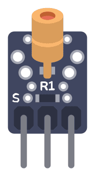
KY-008 Pinout
The KY-008 Ardunio laser module board has three pins.
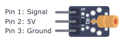
Starting from the pin marked with S, the pins of the laser module are:
- Pin 1: Signal pin (to activate and deactivate laser)
- Pin 2: 5 V
- Pin 3: Ground
How To Connect the Laser Module to Arduino
It’s very straightforward to connect the laser module to an Arduino. First, connect the 5V and Ground pins to 5V and GND on your Arduino. Then connect the Signal pin to any of the digital output pins on your Arduino. By setting the Signal pin high or low, you can turn the laser on and off.
Parts List
To connect the laser module to Arduino, you’ll need the following components:
- Arduino
- Laser Module
- Jumper Wires
Wiring Diagram
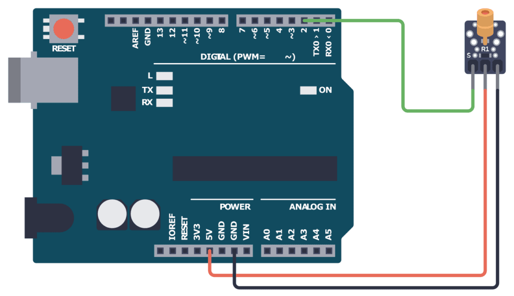
Connect pin 1 (S) of the laser module to pin 2 of the Arduino. Connect pin 2 (VCC) to the 5V pin of the Arduino. Then connect pin 3 (GND) to one of the GND pins of the Arduino.
Arduino Code
// Code for blinking a laser module using Arduino
// Author: Oyvind N. Dahl
// Website: https://www.build-electronic-circuits.com/

void setup() {
  pinMode(2, OUTPUT);
}

void loop() {
  digitalWrite(2, HIGH);
  delay(300);

  digitalWrite(2, LOW);
  delay(700);
}
Open your Arduino IDE and copy the code above. Upload the code to your Arduino, and you should see the Laser blink once every second.

Copyright Build Electronic Circuits
Laser Diode: The Ultimate Beginners Guide
A laser diode is a cool component that you can do a lot of fun stuff with, from engraving wood to creating a light show or giving your robot eyes! They range from super cheap (or even free if you can find one in an old CD player!) to more expensive.
Most types are really easy to use too, once you learn the basics. In this article, you’ll learn the basics of laser diodes and how to use them in your own projects. In the end, I’ll show you how to create your own invisible tripwire!

What Is a Laser Diode?
A laser diode type of diode that creates a very strong and focused beam of light. It is made from a material that can make light waves move in a straight line. This makes the laser beam very powerful and useful for many things, such as cutting or engraving materials, reading data, or even playing with your cat!
A regular Light-Emitting Diode (LED) gives off light in all directions. The laser diode is different because it sends light in only one direction (think of a laser pointer).
How To Use a Laser Diode
You can get laser diodes as standalone components or as modules. For most hobbyist projects, the module is the best choice because it is simpler to use.
Using a Laser Module
If you buy a laser module, you only have to connect it to the right voltage for it to work. That makes it super easy to for example connect to an Arduino.
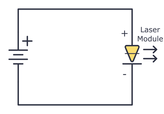
A laser module is an all-in-one device that contains everything you need for the laser diode to work properly. It usually comes in a housing with a black wire and a red wire coming out of it. To turn it on, you just need to connect the correct voltage with plus to the red wire and minus to the black wire.
The exact voltage you need depends on your module. The seller should be able to provide you with that information, or you’ll find it in the datasheet.
Sometimes a laser module comes mounted on a board. On some of these boards, you’ll also find a potentiometer that you can use to adjust the power of the laser.
A common low-power laser diode board is the KY-008. It has three pins, but you only need to connect two of them (plus and minus) to power the laser.
Using a Single Laser Diode
If you buy a single laser diode as a standalone component, you need to set up a driver circuit that controls the current through the laser diode.
A laser diode needs a driver circuit to work properly, and the driver circuit needs to give the laser a constant current. Below you’ll find a simple constant current circuit that uses the LM317 voltage regulator.
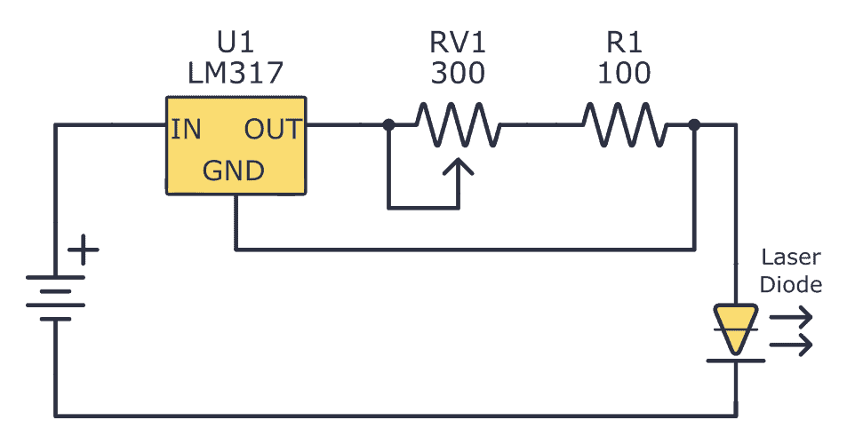
The circuit above was designed to power the OPV332 laser diode. The potentiometer (RV1) enables you to adjust the current up and down to adjust the power of the laser. R1 limits the current to 12 mA, which is the absolute maximum this diode can handle.
If you’re using a different diode, you’ll need to adjust the values so that it fits your specific laser diode. You can learn more about choosing these values from the LM317 datasheet, under section 9.3.3.
Laser Diode With Three Legs
Some laser diodes have three legs:
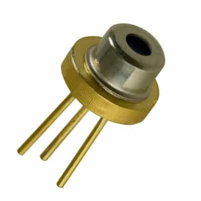
The first pin is the anode, which is the positive pin that provides power to the laser diode.
The second pin is the cathode, which is the negative pin of the laser diode.
The third pin is the monitor photodiode, which is used to monitor the output power of the laser diode. The monitor photodiode measures the amount of light that the laser diode emits. You can feed this back to the driver circuit to ensure that the laser diode is operating at the correct power level.
The monitor photodiode is a key feature of VCSEL laser diodes because it allows for precise control over the output power of the laser. This is important in applications where the laser beam needs to be precisely controlled, such as in fiber-optic communication systems or in 3D sensing applications.
Typical Laser Diode Projects
Laser diodes can be used for a lot of fun projects. Here are a few examples to get you thinking about what’s possible.
Laser engraving and cutting: You can use laser diodes to engrave or cut various materials, such as wood, plastic, and leather. You can do this with a DIY laser engraver or cutter, or by repurposing a laser module from a DVD burner. Check out this DIY laser engraver from Instructables.
Laser light shows: You can use laser diodes to create dazzling laser light shows. By controlling the color, intensity, and pattern of the laser beams, you can create a wide range of visual effects. Check out this instructional video on how to build one.
Robotics: You can use a laser diode as a component in a laser rangefinder to give your robot eyes. You can also use them to create laser-based communication systems between robots or other devices. Here’s an Arduino-based LiDAR project you can check out.
How Much Power Do You Need?
The power of a laser is an important thing to keep in mind. If you want to create a laser cutter that can cut through different materials, you’ll need much more power than if you’re making a simple laser pointer to play with your cat.
Here’s a quick overview of the power needed for different applications:
- Laser pointers: a few milliwatts up to a few hundred milliwatts
- Engraving on softer materials like wood or leather: a few watts
- Cutting harder materials such as acrylic or metal: several watts to tens of watts
You can buy laser diodes for your hobby project in most stores that sell electronic components. If you’re looking for more high-end laser diodes, you can try contacting a laser diode manufacturer directly.
Make an Invisible Tripwire
In this project, you’re going to make an invisible tripwire from a cheap laser module. The circuit is based around the 555 timer in monostable mode. I’ve used a photoresistor in the schematic below, but a photodiode or phototransistor will also work.
What you will need:
- Laser module (such as KY-008)
- Photoresistor
- Active buzzer
- 555 timer
- 10k potentiometer (RV1)
- 2 x 10k resistor (R1-R2)
- 100 µF capacitor (C1)
- BC547 or other NPN transistor (Q1)
The circuit consists of two parts: the laser, which will be on one side of the door or entrance, and the alarm that detects the laser beam, which will be on the other side.
The laser is always on and its beam is aimed at the photoresistor on the other side. When someone walks through the door, the beam is interrupted and the photoresistor turns on a transistor that triggers the 555 timer to sound the alarm for about one second.
Here is the schematic:
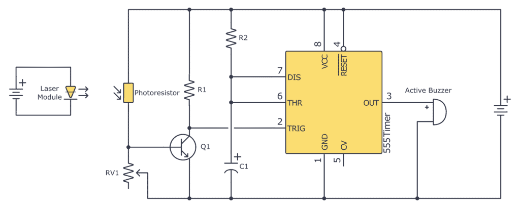
You can increase the value of R2 or C1 to increase the time the alarm is on. Use the 555 Timer Calculator to find the values you need.
Copyright Build Electronic Circuits
Wednesday, 5 July 2023
Identify Electronic Components (Quick Reference)
Not sure what type of component you’re looking at? Use this list to identify electronic components and learn what they do.

9V Battery Clip
To connect a 9V battery to your board.
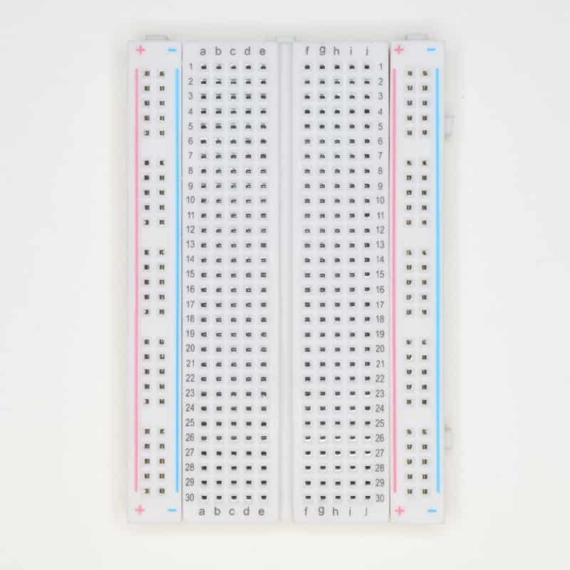
Breadboard
The breadboard is a very handy tool for connecting circuits. You can use it to practice, test ideas, or build simple prototypes.
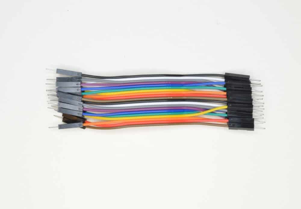
Breadboard wires
To make connections between rows or columns on the breadboard. Also called male-to-male Dupont or jumper wires.
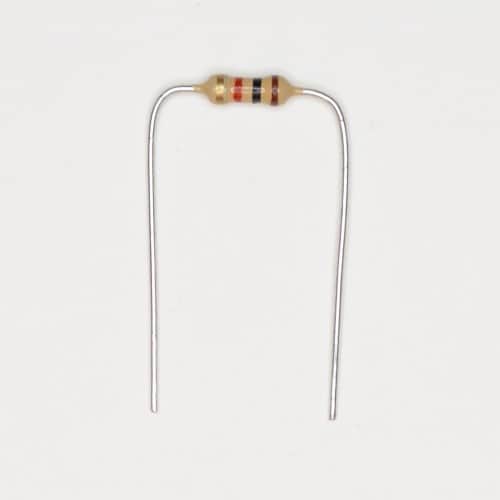
Resistor
The resistor reduces the current in a circuit. To find the value of a resistor you can either measure it with a multimeter, or you can check out our resistor color code calculator.
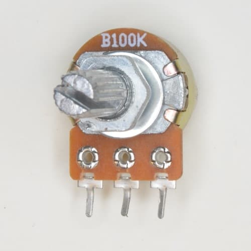
Potentiometer
A potentiometer is basically a resistor that changes resistance when you turn the shaft. Useful for controlling the volume of an amplifier, changing the blinking rate of a blinking light circuit, and much more.
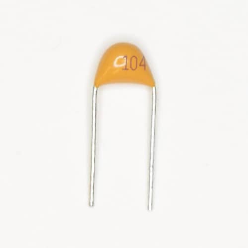
Ceramic Capacitor
Capacitors store energy, similar to a battery. For values up to 0.1 µF, capacitors are often ceramic and not polarized. To find the value of a ceramic capacitor, look up the code printed on it from our capacitor code converter. For example, 104 is 0.1 µF.
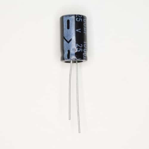
Electrolytic Capacitor
Capacitors store energy, similar to a battery. Capacitors with values of 10 µF and above are often electrolytic capacitors. These are polarized, which means it’s important that you connect the positive leg toward the plus side of the battery in your circuit.
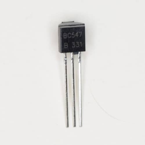
Transistor
You can use the transistor as a switch, or even to amplify signals. There are several types of transistors, and the only way to know what type you have is to check what is written on it. For example, a BC547 is an NPN transistor. But a BC557 is a PNP transistor.
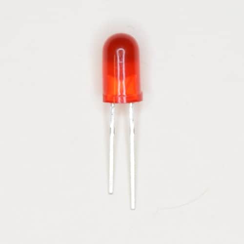
Light-Emitting Diode (LED)
The Light-Emitting Diode (LED) is a component that gives you light, just like a light bulb. The longest leg is the positive leg. If both legs are equally long, look for the flat edge of the LED housing – that’s the negative side.
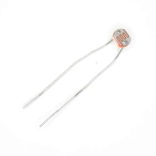
Photoresistor – also called Light Dependent Resistor (LDR)
The photoresistor is a resistor that changes its resistance based on how much light hits its head. It’s a bit slower and less responsive than the photodiode and phototransistor but works well if you don’t need to detect fast changes (like for a remote control).
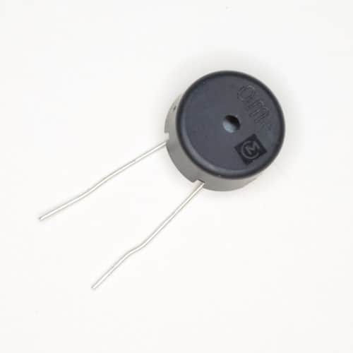
Buzzer
A buzzer is a little component that makes sound. An active buzzer has some internal circuitry that creates a sound signal, so you can make sound by just connecting it to a battery. But a passive buzzer means that it does not have this circuitry, so you have to create an oscillating signal in order to make sound.
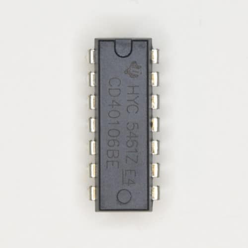
Schmitt Trigger Inverter IC (CD40106)
The CD40106 is an integrated circuit with six Schmitt-triggered inverter gates. Often used to create an oscillator for blinking an LED or making sound.
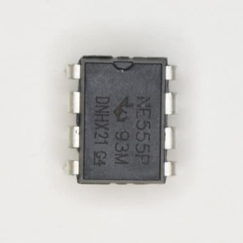
555 Timer IC (NE555)
The 555 Timer is a handy little chip that you can use to blink lights, create sound, add timing operations to your project, and more.
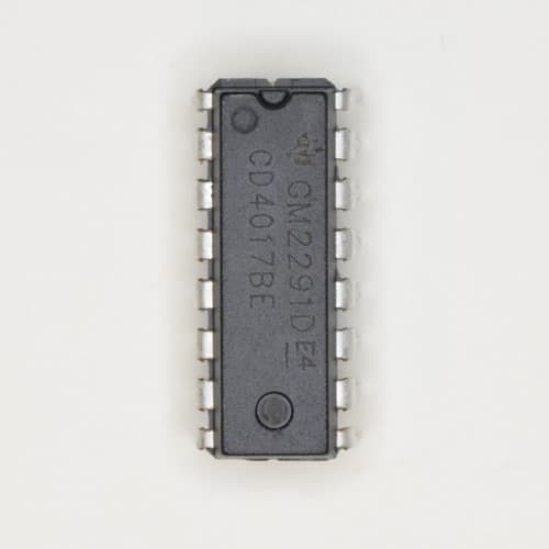
4017 Decade Counter IC (CD4017BE)
The CD4017 Decade Counter IC is a chip that you can use to build several fun circuits. It counts from 1 to 10 and you can build things like the Running LEDs circuit or even an analog synth sequencer.
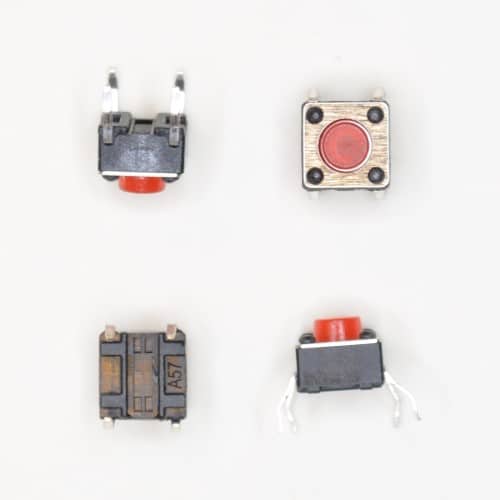
Pushbuttons
Pushbuttons are switches that are normally open, but when you push the button they become closed for as long as you push the button.
Copyright Build Electronic Circuits
-
CMOS (Complementary Metal Oxide Semiconductor) The main advantage of CMOS over NMOS and BIPOLAR technology is the much smaller power dis...
-
I was first introduced to logic gates when I was around 14 years old. I had heard that computers consisted of ones and zeroes. But I didn’t...
-
Bluetooth Controlled Electronic Home Appliances is a simple project, where we can control different electrical appliances and electronic de...


