We are living in times where data is considered the new gold, and in such a world, don’t you think there is a strong need to protect your data from theft? If you’re a corporate, many of your employees will be on travel and they would be accessing your server from different parts of the [...]
New research reveals that the higher-than-expected efficiency of PLEDs can be reached through interactions between triplet excitons, and impurities embedded in their polymer layers.
Researchers have developed the world's first photodetector that can see all shades of light, in a prototype device that radically shrinks one of the most fundamental elements of modern technology.
Scientists have come a step closer to the vision of a broad application of flexible, printable electronics. The team has succeeded in developing powerful vertical organic transistors with two independent control electrodes.
Researchers have developed an ultra-small actuator that can be turned on and off in a fraction of a millisecond and exhibits nanometer-scale position control. This actuator is unparalleled in modern technologies, and will be useful in robotics, medicine, and many other advanced applications.
A new design criteria for enhancing the spin lifetime of a class of quantum materials could support Internet of Things devices and other resource-intensive technologies.
Free electron X-ray lasers deliver intense ultrashort pulses of x-rays, which can be used to image nanometer-scale objects in a single shot. When the x-ray wavelength is tuned to an electronic resonance, magnetization patterns can be made visible. When using increasingly intense pulses, however, the magnetization image fades away. The mechanism responsible for this loss in resonant magnetic scattering intensity has now been clarified.
When you start learning about circuits, you’re bound to ask “what is ground?” at one point or another. Are you actually suppose to connect your circuit into the ground??
First of all: grounding in electronics is different from grounding in high voltage electrical systems. And this article is about electronics (although I’ll mention the other case at the end).
Grounding in electronics
I got an email from a reader a little while back:
«The ground symbol keeps appearing at different points in a circuit and I could not understand why a particular place was chosen for grounding. What is ground?»
Grounding something simply means connecting it to ground.
And in electronics, ground is just a name we give to a certain point in the circuit.
For example, in a circuit with one battery (with a positive and a negative terminal), we usually refer to the negative terminal as ground.
And to simplify drawing the circuit, we use a symbol.
The Ground Symbol
So instead of drawing lines to all the places that should be connected to minus, you instead place the ground symbol there. This makes the circuit diagram much cleaner when there are a lot of connections to minus.
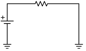
An example circuit using ground symbols
Flow of Current When the Ground Symbol is Shown
To see how the current flows in a circuit diagram with ground symbols, just connect all the points that have ground symbols. That is what you do when you build the circuit.
A schematic using ground symbols
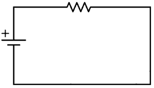
The same schematic shown without ground symbols
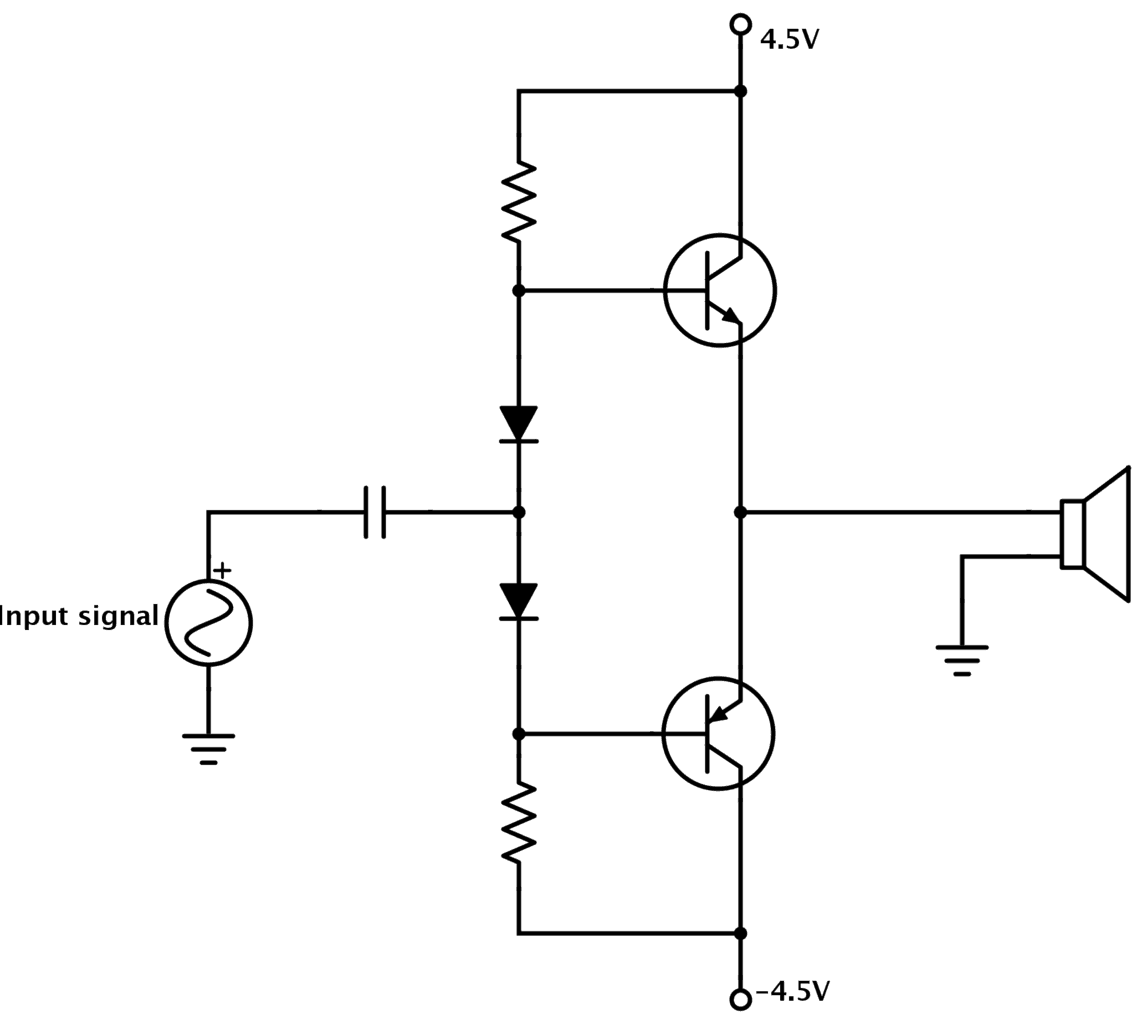
Circuits With Positive, Negative and Ground Connections
In some schematic diagrams, you’ll find a connection to a positive terminal, a negative terminal, and a ground terminal.
This is common in for example amplifier circuits:
So, how does this work?
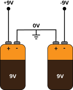
In this scenario, the ground is the middle-point between the positive and the negative terminal. You can create these three voltage points by connecting two power sources in series:
The ground when using dual power supply
Since the ground terminal is in the middle between +9V and -9V, it’s normal to call it zero volts (0V).
Adding calcium to graphene creates an extremely-promising superconductor, but where does the calcium go? In a new study, a Monash-led team has for the first time confirmed what actually happens to those calcium atoms. Surprising everyone, the calcium goes underneath both the upper graphene sheet and a lower 'buffer' sheet, 'floating' the graphene on a bed of calcium atoms.
Researchers presented a highly flexible but sturdy wearable piezoelectric harvester using the simple and easy fabrication process of hot pressing and tape casting. This energy harvester, which has record high interfacial adhesion strength, will take us one step closer to being able to manufacture embedded wearable electronics.
A medical robotic hand could allow doctors to more accurately diagnose and treat people from halfway around the world, but currently available technologies aren't good enough to match the in-person experience. Now researchers have reported that they have designed and produced a smart electronic skin and a medical robotic hand capable of assessing vital diagnostic data by using a newly invented rubbery semiconductor.
The race is on to create natural biocompatible piezoelectric materials for energy harvesting, electronic sensing, and stimulating nerves. A group of researchers has explored peptide-based nanotubes and reports using a combination of ultraviolet and ozone exposure to generate a wettability difference and an applied field to create horizontally aligned polarization of nanotubes on flexible substrates with interlocking electrodes. The work will enable the use of organic materials more widely.
An Australian collaboration reviews the quantum anomalous Hall effect (QAHE), one of the most fascinating and important recent discoveries in condensed-matter physics. QAHE allows zero-resistance electrical 'edge paths' in emerging quantum materials such as topological insulators, opening great potential for ultra-low energy electronics.
Quantum technology holds great promise: Quantum computers are expected to revolutionize database searches, AI systems, and computational simulations. Today already, quantum cryptography can guarantee secure data transfer, albeit with limitations. The greatest possible compatibility with current silicon-based electronics will be a key advantage. And that is precisely where physicists have made progress: The team has designed a silicon-based light source to generate single photons that propagate well in glass fibers.
I was first introduced to logic gates when I was around 14 years old. I had heard that computers consisted of ones and zeroes. But I didn’t understand what that really meant.
So I asked my father to explain it. And I loved his explanation because it was so simple and easy to understand. Read that article first if you’re not sure what a 1 and a 0 is yet.
Logic gates are components that we use for “doing stuff” with the 1s and 0s. You can combine them to create building blocks like flip-flops, adders, and more. Which you can use to build calculators, Arduinos, and even smartphones and computers!
Below, you’ll find an overview of the logic gates, their logic gate symbols, and how they work.
NOT gate/Inverter
The simplest logic gate of all is the NOT gate. It takes one bit as input (A). And it gives as an output (Y) what is NOT on the input. So if there is a 1 on the input, its output is 0. And if there is 0 on the input, its output is 1. It’s also called an inverter.
Input (A)
Output (Y)
0
1
1
0
NOT Gate Truth Table
AND gate
The AND gate takes two (or more) inputs and gives out a 1 if all the inputs are 1. Otherwise, it gives out a 0.
The truth table is below, but all you really need to remember is that the AND gate needs a 1 on input A and input B to give out 1.
Input A
Input B
Output Y
0
0
0
0
1
0
1
0
0
1
1
1
AND Gate Truth Table
OR gate
The OR gate takes two (or more) inputs and gives out a 1 if any of the inputs are 1. Otherwise, it gives out a 0.
The truth table is below, but all you really need to remember is that the OR gate needs a 1 on input A or input B to give out 1.
Input A
Input B
Output Y
0
0
0
0
1
1
1
0
1
1
1
1
OR Gate Truth Table
NAND gate
The NAND (or NOT AND) gate operates in the opposite way of the AND gate. It’s like if an AND gate had a NOT gate on its output:
Input A
Input B
Output Y
0
0
1
0
1
1
1
0
1
1
1
0
NAND Gate Truth Table
NOR gate
The NOR (or NOT OR) gate operates in the opposite way of the OR gate. It’s like if an OR gate had a NOT gate on its output.
Input A
Input B
Output Y
0
0
1
0
1
0
1
0
0
1
1
0
NOR Gate Truth Table
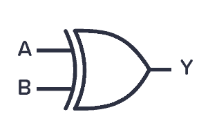
XOR gate
The XOR (or Exclusive OR) gate outputs 1 if its two inputs are not equal.
Input A
Input B
Output Y
0
0
0
0
1
1
1
0
1
1
1
0
XOR Gate Truth Table
XNOR gate
The XNOR (or Exclusive NOT OR) gate outputs 1 if its two inputs are equal. It basically works like an XOR gate with an inverter on the output.
Input A
Input B
Output Y
0
0
1
0
1
0
1
0
0
1
1
1
XNOR Gate Truth Table
Using Logic Gates in Circuits
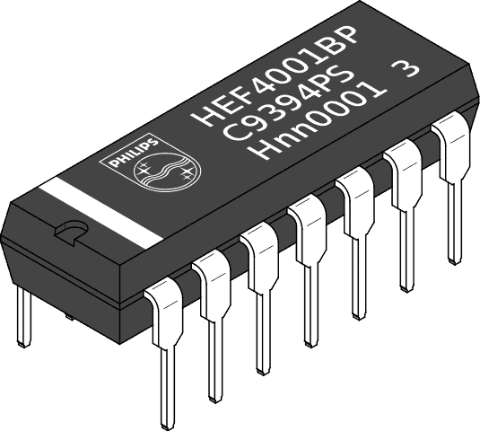
A logic gate can be built with transistors and usually comes as an Integrated Circuit (IC).
There are two classic IC series that contain a lot of the same functions; the 7400-series and the 4000-series.
The 7400-series is the oldest series. The 4000-series was introduced as a lower-power and more versatile option to the 7400. But today, several families of the 7400-series exist, some with similar properties as the 4000-series.
Scientists describe the quirky behavior of one such magnetic topological insulator. The new article includes experimental evidence that intrinsic magnetism in the bulk of manganese bismuth telluride (MnBi2Te4) also extends to the electrons on its electrically conductive surface. Such materials could be just right for making qubits, but this one doesn't obey the rules.
Ultrathin layers of tungsten diselenide have potential applications in opto-electronics and quantum technologies. Researchers have now explored how this material interacts with light in the presence of strong magnetic fields.
Researchers have created a single chip that combines a transistor and micro-fluidic cooling system. Their research should help save energy and further shrink the size of electronic components.
Engineers have invented a soft wearable device which simulates the sense of touch and has wide potential for medical, industrial and entertainment applications.
Researchers developed a new class of medical instruments equipped with an advanced soft electronics system that could dramatically improve the diagnoses and treatments of a number of cardiac diseases and conditions.
Researchers have successfully demonstrated a room-temperature coherent amplification of terahertz (THz) radiation in graphene, electrically driven by a dry cell battery.
Structural coloration is promised to be the display technology of the future as there is no fading - it does not use dyes - and enables low-power displays without strong external light source. However, the disadvantage of this technique is that once a device is made, it is impossible to change its properties so the reproducible colors remain fixed. Recently, a research team has successfully obtained vivid colors by using semiconductor chips - not dyes - made by mimicking the human brain structure.
Researchers have demonstrated the use of elastic vibrations to manipulate the spin states of optically active color centers in SiC at room temperature. They show a non-trivial dependence of the acoustically induced spin transitions on the spin quantization direction, which can lead to chiral spin-acoustic resonances. These findings are important for applications in future quantum-electronic devices.
I learned how to use an oscilloscope pretty much on my own. The first time I tried one, I only got some simple instructions, then I was left to myself to figure things out.
But I found that it wasn’t really that hard…
The oscilloscope can be a bit overwhelming with all its functions. But you don’t need to know every detail of it. You can actually come a long way by knowing just a few simple things.
So I want to pass those simple things on to you, so that you can start using an oscilloscope on your own.
Knowing how to use an oscilloscope is very useful when building electronic circuits. When your circuit is not working, it will help you figure out what is going on.
What Does an Oscilloscope Do?
The oscilloscope measures voltage over time. This means that it lets you see the signal in the circuit as it changes with time.
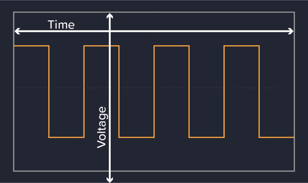
For example if you measure the voltage to a blinking LED with an oscilloscope, you’ll see something like this:
The orange line represents the voltage. When it is on top, the voltage is high and the LED is on. And when it’s at the bottom, the voltage is low and the LED is off.
But when do you need this?
Let’s say you build a music player. But when you plug in the power, it doesn’t work. There is no sound coming…
With an oscilloscope, you can measure different points in your circuit where the sound signal should be and see if it’s actually there or not.
Something you wouldn’t be able to do with a multimeter.
This makes it much easier to debug the circuit:
First, you can measure where the sound signal enters the circuit.
No signal? Aha! Then there is a problem with the sound source.
If there is a signal there, you continue to the next part of the circuit that the sound goes through. No sound there? Well, then that part must be the problem. And so on…
How To Use An Oscilloscope
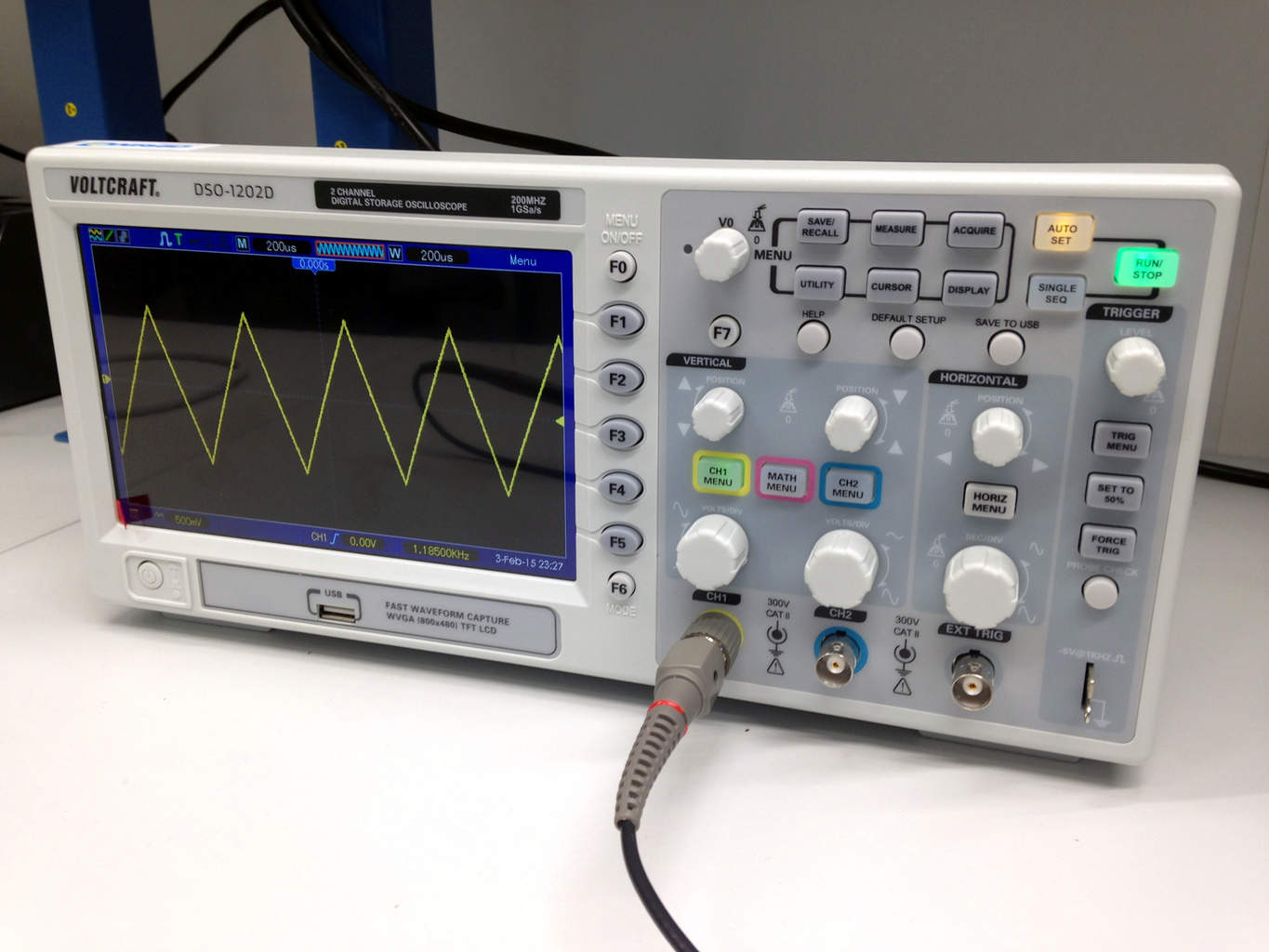
A typical oscilloscope looks like this:
All these buttons are a bit intimidating right? Well, don’t worry, I’ll teach you a shortcut in just a second.
The wires you use to measure with, are named probes.
So the first thing you do, is to attach the probes to what you want to measure. The oscilloscope measures voltage. And since voltage is always measured between two points, you need to connect both the negative and positive side of the probe.
In most situations, you connect the negative probe to ground or minus in your circuit. Then connect the positive side to the thing you want to measure.
When connected, it’s time to set the oscilloscope to the right settings.
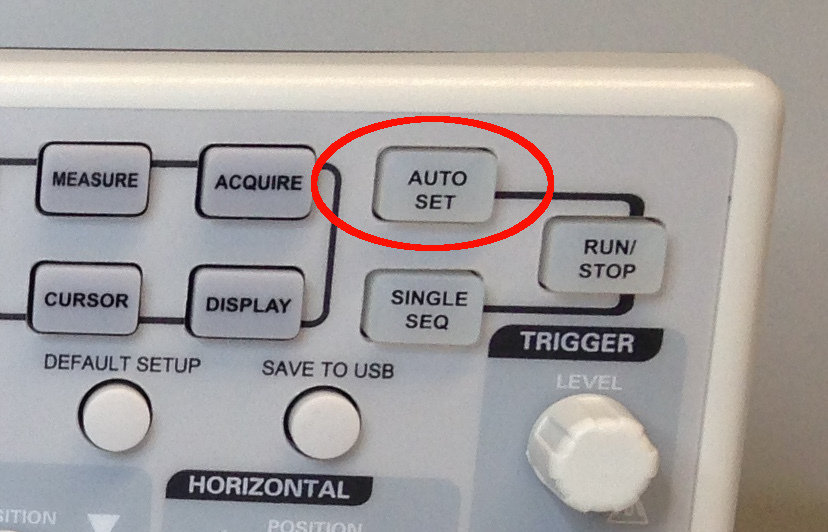
But there are sooooo many buttons! So here is a super secret (or not-so-secret) trick on how to use an oscilloscope:
Push the «Auto Set» button.
This button will analyze the signal and try to set the settings of the scope to what is best. It doesn’t always work – but in many situations it does.
Control Your Oscilloscope Manually
What if you want to know how to use an oscilloscope without the «Auto Set» – like old-school analog oscilloscope for example?
Then, there are two main knobs to focus on:
Vertical Volts/Div
Horizontal Sec/Div
If the signal you are looking at has large voltage swings, you need to adjust the vertical knob marked «Volts/Div» to a large Volts/Div setting. If it has very small voltage swings, you need to set it you a tiny Volts/Div setting.
If your signal is not in the screen, then scroll up or down on the vertical knob marked «Position» to find your signal.
Then use the horizontal Sec/Div knob to set the time per division on the screen. If you have a signal with really high frequency, you need a low Sec/Div setting to see it properly. If you have a very low frequency signal, you need to set it higher.
These settings are basically all you need to get started.
Where To Buy An Oscilloscope
Now that you know how to use an oscilloscope, it’s time to get yourself one. A very good oscilloscope that’s useful for beginners, as well as more advanced circuit builders, is the Rigol DS1054Z.
If you want to save some money, look for USB oscilloscopes. These are scopes that you plug into the USB of your computer and look at the signal in some computer software.
Or you can learn how to build your own super simple Arduino oscilloscope – but keep in mind that it’s simple for a reason (it’s also pretty bad).
Questions?
Do you have any questions about how to use an oscilloscope? Let me know in the comments below!
New pain-sensing prototype mimics the body's near-instant feedback response and reacts to painful sensations with the same lighting speed that nerve signals travel to the brain. It's a significant advance towards next-generation biomedical technologies, smart prosthetics and intelligent robotics.
Extremely energy-efficient artificial intelligence is now closer to reality after researchers found a way to improve the accuracy of a brain-inspired computing system.