Wednesday, 30 August 2023
Brighter comb lasers on a chip mean new applications
Tuesday, 29 August 2023
A lightweight wearable device helps users navigate with a tap on the wrist
Monday, 28 August 2023
Arduino Light Sensor – Circuit and Code Example
This Arduino Light sensor circuit is a simple example that shows you how to connect light sensors such as photoresistors, photodiodes, and phototransistors, to an Arduino.
In this quickstart guide, you’ll learn how to connect a photoresistor to an Arduino board and read out the voltage. You’ll first use the Serial Monitor to learn about how the light sensor behaves, then you build a circuit that automatically turns on a light when it gets dark.
This is a great practice circuit when you’re learning Arduino. The code is straightforward and the light sensor connections are simple.
Parts Needed
- Arduino Uno
- Breadboard (and some breadboard wires)
- Photoresistor – also called Light Dependent Resistor (LDR) *
- Resistor 10 kΩ
- Wires
* A photodiode or phototransistor will also work.
Connecting a Light Sensor to an Arduino
To connect a light sensor to an Arduino, connect the light sensor in series with a resistor between 5V and GND. Then connect the middle point between the resistor and light sensor to an analog input pin on the Arduino.
This setup works with photoresistors, photodiodes, and phototransistors.

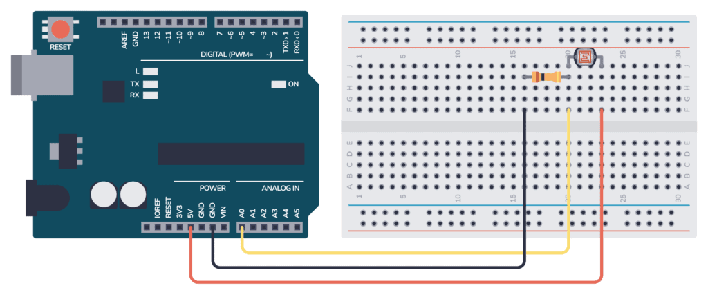
Connecting the Arduino Light Sensor on a Breadboard
Here’s how you can connect this circuit to an Arduino by using a breadboard and some cables:
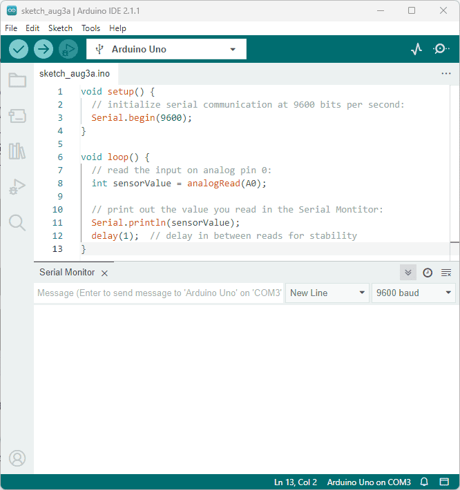
Arduino Light Sensor Code
This Arduino code is an example of reading the voltage from the light sensor (connected to analog pin A0) and then printing the value of the analog reading to the Serial Monitor.
There’s also some code that will try to determine if it’s dark, dim, light, bright, or very bright. You’ll have to tweak the thresholds in order for it to work with your sensor.
An analog pin will give you a value between 0 and 1023, where 0 means 0V and 1023 means the maximum voltage possible (usually 5V).
As with all Arduino code, you have the two main functions setup() and loop():
- Inside setup(), you need to configure the Serial port so that you can read out values.
- Inside loop(), you need to read the analog input and print this value out on the Serial port.
void setup() {
  // Setup serial communication at baudrate 9600 for reading the light sensor
  Serial.begin(9600);
}

void loop() {
  // reads the input on analog pin A0
  int lightValue = analogRead(A0);

  // Print out the values to read in the Serial Monitor
  Serial.print("Analog reading (0-1023): ");
  Serial.print(lightValue);

  // Use the value to determine how dark it is
  // (Try tweaking these to make it more accurate)
  if (lightValue < 10) {
    Serial.println(" - Dark");
  } else if (lightValue < 200) {
    Serial.println(" - Dim");
  } else if (lightValue < 500) {
    Serial.println(" - Light");
  } else if (lightValue < 800) {
    Serial.println(" - Bright");
  } else {
    Serial.println(" - Very bright");
  }

  delay(500);
}
How the Code Works
Inside the setup() function there is only one line: Serial.begin(9600); This line sets up the serial port of the Arduino so that it’s possible to send data out from the Arduino and into your computer.
Inside the loop() function there are four sections:
int lightValue= analogRead(A0);: This line reads the analog voltage present at analog pin A0. It returns a value between 0 and 1023, representing the voltage level on the pin relative to the reference voltage (usually 5V for most Arduino boards). The value is stored in the variablelightValue.Serial.println(lightValue);: This line prints the value of lightValue to the Serial Monitor so you can read it.if (lightValue < 10) { ...These lines will use predetermined thresholds to determine if it’s dark, dim, light, bright, or very bright. You’ll have to tweak the thresholds to make them work for your sensor.delay(500);: This line adds a small delay of 500 milliseconds between each reading and printing. This delay prevents the code from running too quickly. This way it’s easier to read the readings on the Serial Monitor.
The end result of this code is that it continuously reads the analog voltage at pin A0, prints the reading (a number between 0 and 1023) and a brightness value (dark, dim, light, bright, or very bright) to the Serial Monitor, and repeats the process in a loop.
When you put your hand over the sensor, the amount of light it detects will change, and you can observe the changing values in the Serial Monitor. This is a helpful way to visualize the data and debug when things aren’t working as expected.
Using The Serial Monitor
To use the Serial Monitor to check the results from the code above, follow these steps:
- Connect your Arduino board to your computer using a USB cable.
- Upload the provided code to your Arduino board using the Arduino IDE.
- Open the Serial Monitor by clicking the magnifying glass icon or using the keyboard shortcut
Ctrl + Shift + M(Windows/Linux) orCmd + Shift + M(Mac). - Set the baud rate in the Serial Monitor to 9600 (or the same value as in the
Serial.begin()function in the code). - Read the output in the Serial Monitor.
- Place your hand over the light sensor to see how the readings change in real-time.
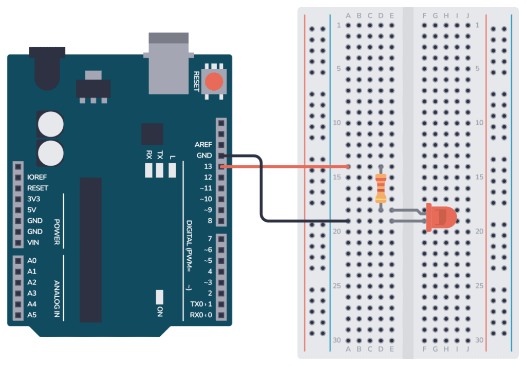
Example: Dark-Activated LED
Here’s an example circuit where a Light-Emitting Diode (LED) is turned on when it gets dark. You could easily replace the LED with something more powerful if you want to control an outdoor light. You can learn more about how to do that in our transistor tutorial.
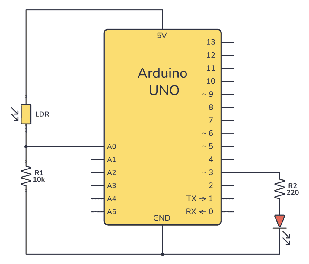
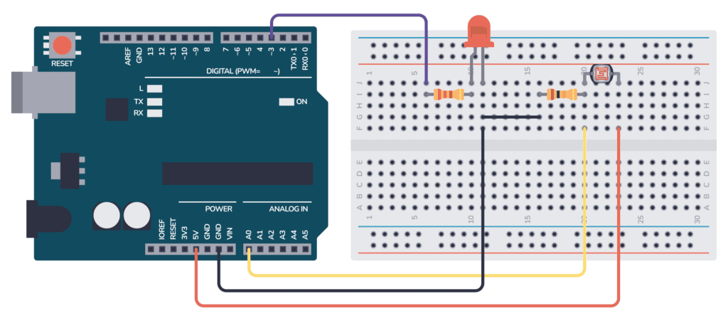
Here’s how to connect the circuit on a breadboard:
The Code
// Definition of constants - values that will never change
const int LIGHT_SENSOR = A0;
const int LED          = 3;

// Definition of variables - values that can change
int analogValue;

void setup() {
  // Set the LED pin as an output
  pinMode(LED, OUTPUT);
}

void loop() {
  // read the input from the analog pin
  analogValue = analogRead(LIGHT_SENSOR);

  // Check if it's above a specific threshold and turn the LED on or off
  if(analogValue < 700)
    digitalWrite(LED, HIGH); // turn on LED
  else
    digitalWrite(LED, LOW);  // turn off LED
}
Copyright Build Electronic Circuits
Friday, 25 August 2023
DNA chips as storage media of the future: What challenges need to be overcome
Towards better batteries and fuel cells with dispersibility estimation for carbon electrode slurries
Tuesday, 22 August 2023
New epoxy resin resists flames and reduces waste
Tuesday, 15 August 2023
Weaker transcription factors are better when they work together
Friday, 11 August 2023
Arduino Button – Circuit and Code Example
This Arduino button circuit is a simple example that shows you how to connect buttons to an Arduino.
In this quickstart guide, you’ll learn how to connect a button to an Arduino board and read a HIGH or LOW depending if the button has been pushed or not. You’ll use the Light-Emitting Diode (LED) that is included on the board to turn on and off with the button so that you can verify that your button press code is working properly.
This is a great practice circuit to build as you’re learning Arduino. The code is straightforward and the connections are simple.
Parts Needed
- Arduino Uno
- Breadboard (and some breadboard wires)
- Resistor 10 kΩ
- Pushbutton or Switch
- Wires
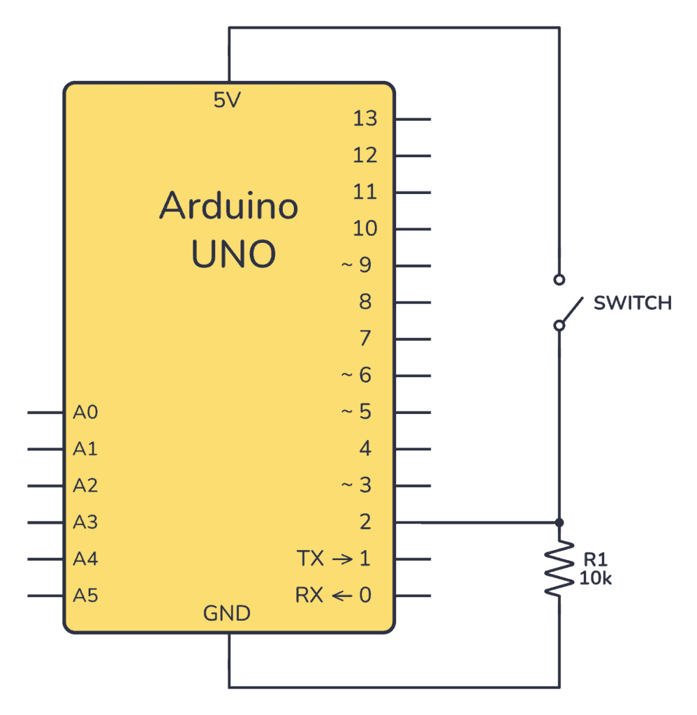
Arduino Button Circuit
To connect a button to an Arduino, you’ll need a pull-down or a pull-up resistor. This is to make sure that when the button is not pushed, it has a defined value. In this example, we’re using a pull-down resistor of 10 kΩ.
Connecting On a Breadboard
Here’s how you can connect a potentiometer to an Arduino by using a breadboard and some cables:
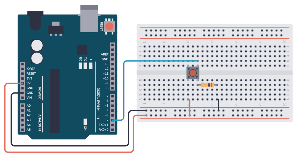
Connect one side of the pushbutton to the 5V pin on the Arduino. And connect the other side to the digital input D2 on the Arduino. Connect a resistor from D2 (and the button) to ground.
Arduino Button Code
The following code reads the button state, then turns the onboard LED either on or off, based on if the button was pushed or not.
As with all Arduino code, the code is structured around the two main functions setup() and loop():
- Inside setup(), you need to set what pins should be inputs and outputs.
- Inside loop(), you need to read the button input and set the LED pin based on the button state.
Check out the complete code:
const int buttonPin = 2;  // the number of the pushbutton pin
const int ledPin = 13;    // the number of the LED pin

// variables will change:
int buttonState = 0;  // variable for reading the pushbutton status

void setup() {
  // initialize the LED pin as an output:
  pinMode(ledPin, OUTPUT);
  // initialize the pushbutton pin as an input:
  pinMode(buttonPin, INPUT);
}

void loop() {
  // read the state of the pushbutton value:
  buttonState = digitalRead(buttonPin);

  // check if the pushbutton is pressed. If it is, the buttonState is HIGH:
  if (buttonState == HIGH) {
    // turn LED on:
    digitalWrite(ledPin, HIGH);
  } else {
    // turn LED off:
    digitalWrite(ledPin, LOW);
  }
}
How the Code Works
Here’s an overview of how the code works:
- Variables & Constants:
buttonPin: Pin 2 where the button is connected.ledPin: Pin 13 where the LED is connected.buttonState: Stores the status (HIGH or LOW) of the pushbutton.
setup():- Sets
ledPinto OUTPUT andbuttonPinto INPUT.
- Sets
loop():- Reads the pushbutton’s state.
- If button is pressed (HIGH), the LED turns on.
- Else, the LED turns off.
So in this code, pressing the button on pin 2 toggles the LED on pin 13.
Copyright Build Electronic Circuits
Potential application of unwanted electronic noise in semiconductors
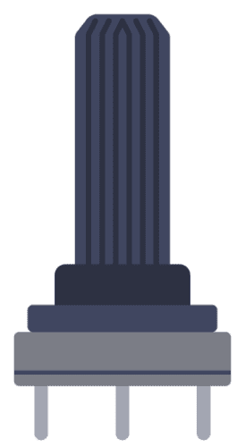
The Potentiometer: Pinout, Wiring, and How It Works
A potentiometer is an adjustable resistor with three pins. The fact that it has three pins instead of two was confusing to me when I was starting to learn electronics. But as soon as I saw the inside of it, it all made sense.
In this guide, I’ll show you what the potentiometer looks like on the inside, the different potentiometer types, and examples of how to wire it up for different circuits.
What Is A Potentiometer?
Potentiometers are adjustable resistors used in circuits for many things, such as to control the volume of an amplifier, control the brightness of a light, and much more.
It is like the resistor. But while the resistance value of a resistor stays the same, you can adjust the resistance value of a potentiometer.
A potentiometer has three pins and the schematic symbol looks like this:

But you don’t need to use all three pins if you don’t need them. It’s totally fine to use just two pins.
Once you learn how it’s made, you’ll quickly understand how to do that. But you can also jump right to the wiring examples at the end if you just want to see some examples of how to connect a potentiometer.
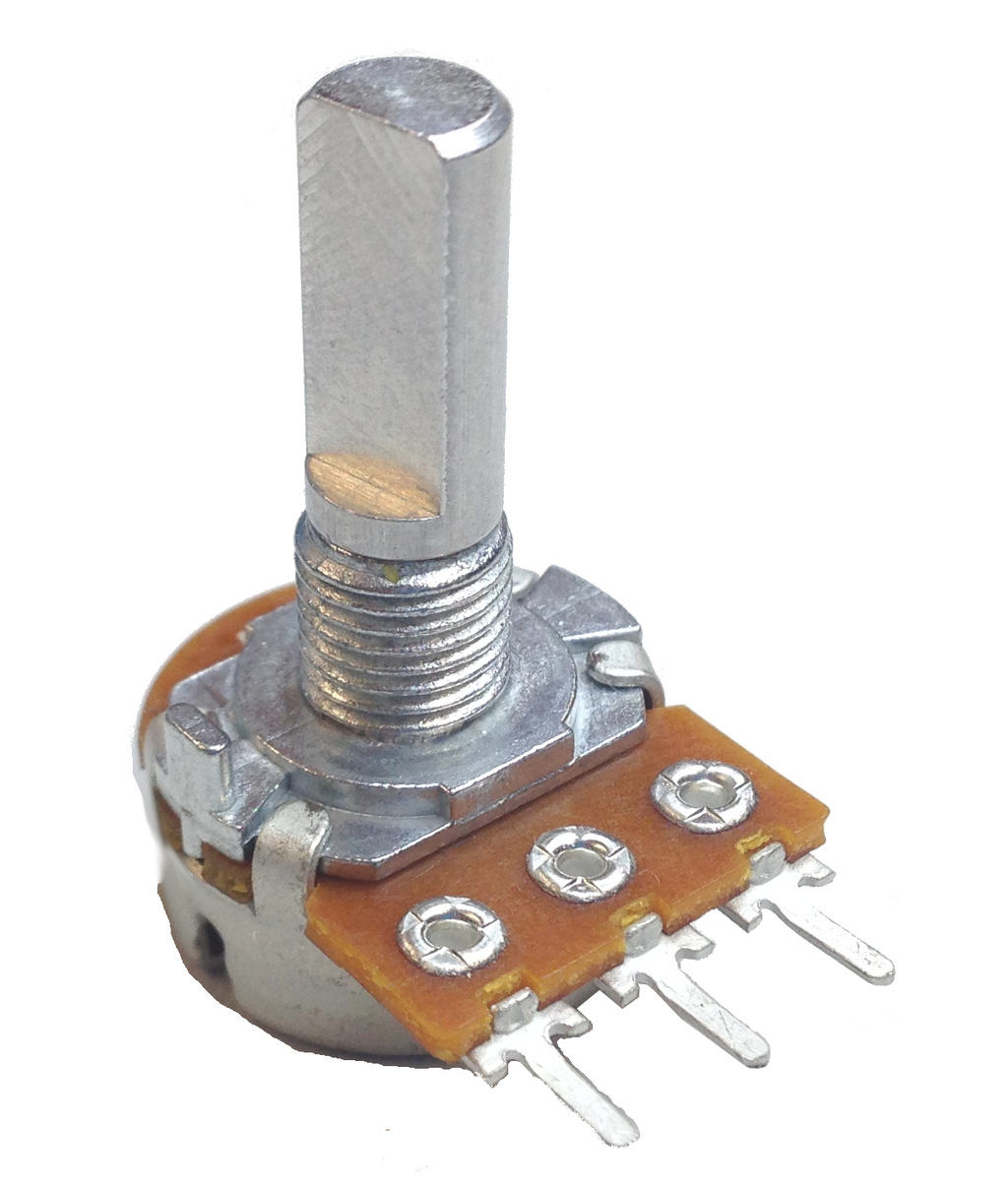
How Potentiometers Are Made
A potentiometer is made of a strip of resistive material, usually a carbon mixture. Plus a wiper that can be adjusted and placed somewhere on that strip.
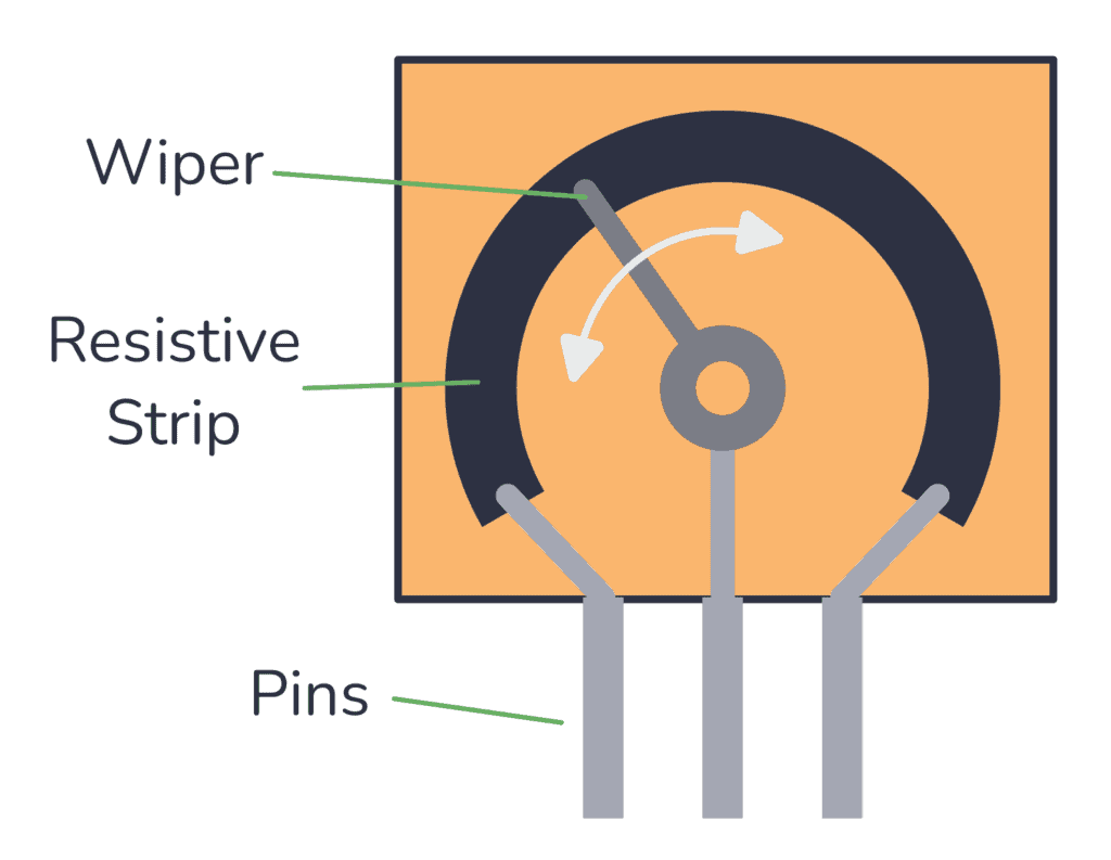
Each far side of the strip is connected to a pin. And the middle pin is connected to the wiper.
The wiper touches the strip somewhere between the two ends. The position of the wiper determines the resistance between the wiper and the side pins. You can move the point where the wiper connects to the carbon strip by turning the shaft of the potentiometer.

When you move the wiper to the left side, the resistance between the middle pin and the left pin decreases. And the resistance between the middle pin and the right pin increases.
Move the wiper to the right, and the opposite happens.
When you buy a potentiometer, you have to choose a value. For example 100k. This is the value you get if you measure the resistance between the two end pins. And it’s the largest resistance value you can get from the potentiometer.
Potentiometer Types
Rotary Potentiometer
This is the most common type. It has a shaft that can be turned, and the resistance changes as you turn the shaft. It’s often used for adjusting the volume on guitar pedals, audio amplifiers, and other audio equipment.
This type of potentiometer can be found with values that change linearly or exponentially. The exponential version of the pot is usually used for adjusting audio volume.
Dual or Stereo Potentiometer
This is the same as the rotary potentiometer, just that it contains two potentiometers operated by a single shaft. This makes it possible to control two channels at the same time, such as the left and right channels of a stereo system.
Linear or Slide Potentiometer
A slide (or linear) potentiometer looks like a slider and you change the resistance as you move a slider or wiper in a straight line.
This type of potentiometer is commonly found in audio mixing consoles as faders.
Trimmer or Trimpot
A trimmer potentiometer, also called a “trimpot”, is small and is often used for occasional adjustments, such as during setup or calibration. It’s typically mounted on PCBs and adjusted using a small screwdriver.

Digital Potentiometer
A digital potentiometer is a chip where you can adjust the position of the wiper through digital signals, such as SPI or I2C.
This can be very useful if you want to be able to change resistance on-the-fly from an Arduino or other microcontroller. For example to adjust LED brightness.

Potentiometer Wiring Examples
The way to wire up a potentiometer depends on how you’re planning to use it.
Usually, the middle pin is the wiper. And the resistance between the wiper and the right pin will decrease as you turn the shaft (or move the slider) to the right. If you move it to the left, the resistance between the left pin and the wiper will decrease.
Sometimes, it makes sense to use all three pins. Other times, you only want to use two. Let’s look at some examples.
Wiring Example #1: Potentiometer as a Simple Variable Resistor
If you need a simple resistor that you can change the resistance of, you only need two pins: the middle pin and one of the side pins.
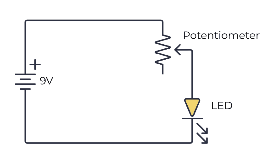
The above image shows a simple circuit to dim a Light-Emitting Diode (LED). In a real circuit, you might want to add an extra resistor in series to make sure you don’t destroy the LED even if you adjust all the way to one side so that the resistance becomes zero.
Turn the shaft in one direction and the resistance increases so that the LED becomes dimmer. Turn it in the other direction and the resistance decreases and the LED becomes brighter.
Wiring Example #2: Connecting the Third Pin to the Middle
Sometimes you’ll see circuit diagrams where the middle and bottom pins are connected to the same point. Why?
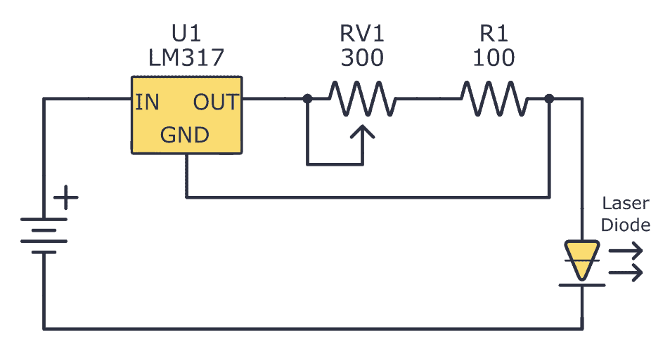
This way of connecting is actually equal to using only two pins. Connecting the third pin to the middle pin does not affect the resistance at all.
So why do it?
Some people prefer it this way because they feel it’s a bit messy having an unconnected pin, so they connect it like this. It also makes the circuit diagram a little bit nicer-looking I think.
Wiring Example #3: Potentiometer as Volume Control
This example uses all three pins of the potentiometer to create a simple way of adjusting the volume of an audio amplifier.

By connecting it like this, you’ll get a voltage divider that decreases the voltage of the input signal. The more you turn the shaft, the more you decrease the volume.
This wiring is very common in audio equipment.
Copyright Build Electronic Circuits
Monday, 7 August 2023
Unveiling the anomalous dynamics of non-collinear antiferromagnets
Thursday, 3 August 2023
Arduino Potentiometer – Circuit and Code Example
This Arduino Potentiometer circuit is a simple example that shows you how analog inputs work, and how you can use the Serial Monitor to learn about what is going on inside the chip.
In this quickstart guide, you’ll learn how to connect a potentiometer to an Arduino board and read out the voltage. This is a great practice circuit when you’re learning Arduino. The code is straightforward and the potentiometer connections are simple.
Parts Needed
- Arduino Uno
- Breadboard (and some breadboard wires)
- Potentiometer (Any value above 200 Ω will work)
Arduino Potentiometer Circuit
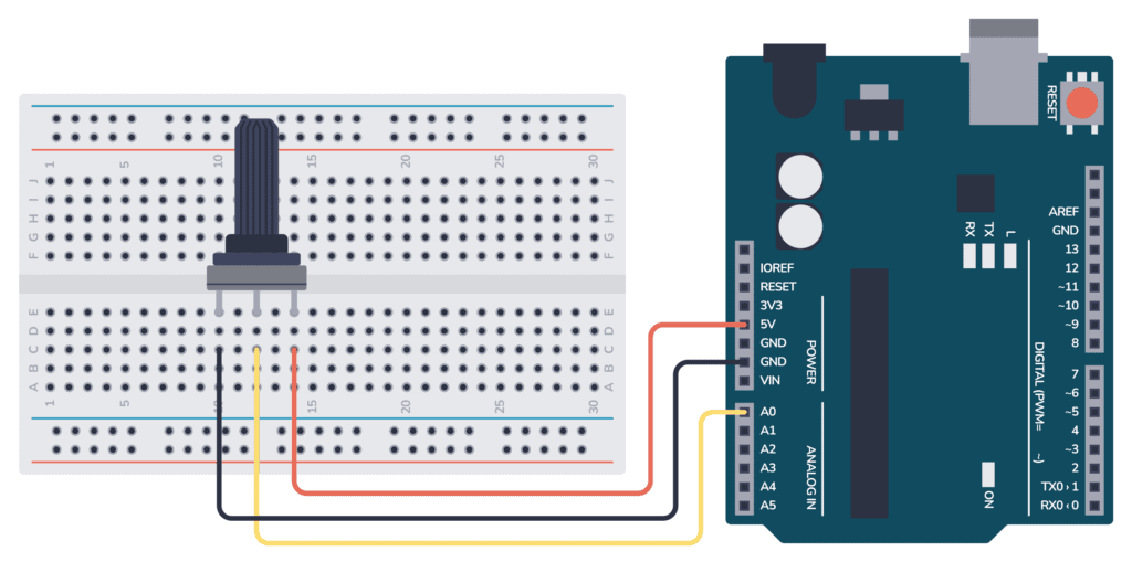
To connect a potentiometer to an Arduino, connect the middle pin of the potentiometer to an analog input pin on the Arduino. Then connect the outer pins to 5V and GND.
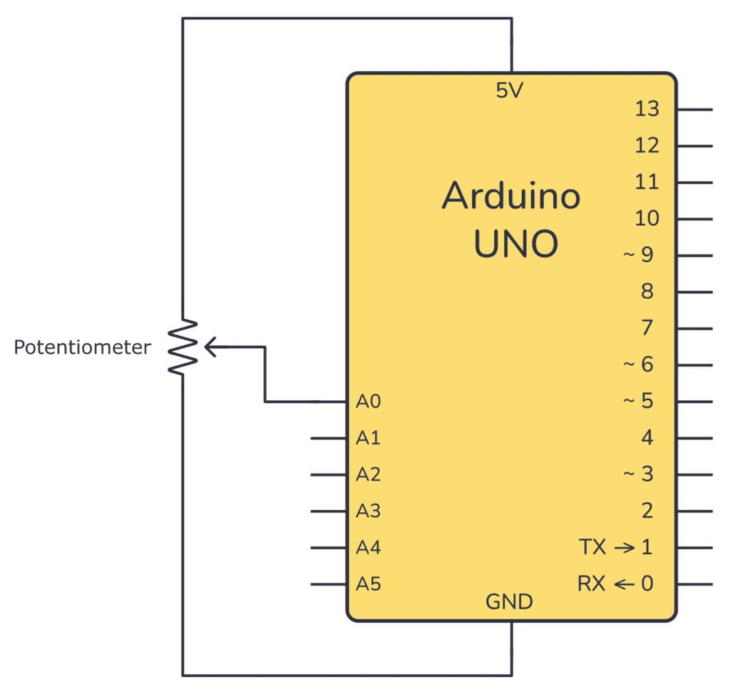
Connecting On a Breadboard
Here’s how you can connect a potentiometer to an Arduino by using a breadboard and some cables:
Arduino Potentiometer Code
This Arduino code is an example of reading the voltage from the potentiometer (connected to analog pin A0) and then printing the value of the analog reading to the Serial Monitor.
An analog pin will give you a value between 0 and 1023, where 0 means 0V and 1023 means the maximum voltage possible (usually 5V).
As with all Arduino code, you have the two main functions setup() and loop():
- Inside setup(), you need to configure the Serial port so that you can read out values.
- Inside loop(), you need to read the analog input and print this value out on the Serial port.
Check out the complete code:
void setup() {
  // initialize serial communication at 9600 bits per second:
  Serial.begin(9600);
}

void loop() {
  // read the input on analog pin 0:
  int sensorValue = analogRead(A0);

  // print out the value you read in the Serial Montitor:
  Serial.println(sensorValue);
  delay(1);  // delay in between reads for stability
}
How the Code Works
Inside the setup() function there is only one line: Serial.begin(9600); This line sets up the serial port of the Arduino so that it’s possible to send data out from the Arduino and into your computer.
Inside the loop() function there are three lines:
int sensorValue = analogRead(A0);: This line reads the analog voltage present at analog pin A0. It returns a value between 0 and 1023, representing the voltage level on the pin relative to the reference voltage (usually 5V for most Arduino boards). The value is stored in the variablesensorValue.Serial.println(sensorValue);: This line prints the value ofsensorValueto the Serial Monitor so that you can read it.delay(100);: This line adds a small delay of 100 milliseconds between each reading and printing. This delay prevents the code from running too quickly. This way it’s easier to read the readings on the Serial Monitor.
The end result of this code is that it continuously reads the analog voltage at pin A0, prints the reading (a number between 0 and 1023) to the Serial Monitor, and repeats the process in a loop.
When you turn the potentiometer, the voltage out from the potentiometer will change, and you can observe the changing values in the Serial Monitor. This is a helpful way to visualize the data and debug when things aren’t working as expected.
Using The Serial Monitor
To use the Serial Monitor to check the results from the code above, follow these steps:
- Connect your Arduino board to your computer using a USB cable.
- Upload the provided code to your Arduino board using the Arduino IDE.
- Open the Serial Monitor by clicking the magnifying glass icon or using the keyboard shortcut
Ctrl + Shift + M(Windows/Linux) orCmd + Shift + M(Mac). - Set the baud rate in the Serial Monitor to 9600 (or the same value as in the
Serial.begin()function in the code). - Observe the continuous stream of numbers in the Serial Monitor. These numbers represent the analog readings from pin A0.
- Adjust the potentiometer to see how the readings change in real time.
- Close the Serial Monitor when you’re done by clicking the “x” button in the top-right corner.
Copyright Build Electronic Circuits
Wednesday, 2 August 2023
Faster thin film devices for energy storage and electronics
What is Arduino and How Do I Get Started?
Arduino is a microcontroller board that makes it really easy to program electronics. It’s an easy way to get started with microcontrollers that I highly recommend since it lets you jump right into the code and do stuff from the start.
You can use it both for building simple things like a blinking LED – and advanced stuff like building an internet-connected robot. With Arduino, it’s simple to build really cool electronics projects without learning a bunch of theory. And it’s fun!
It has several inputs and outputs that are controlled by simple commands that you write into a program on your computer.
What Is Arduino Used For?
Arduino is a board with a microcontroller that can easily be programmed from the Arduino IDE.
A microcontroller is a small chip with several input and output pins. You can write code, for example, to set an output to be HIGH or LOW. And if you connect a Light-Emitting Diode (LED) to that output, the LED will turn on and off, depending if the output is HIGH or LOW.
This is really cool because it means you can control things in the real world with code!
And you’re not limited to just blinking LEDs. You can build your own remote control. Or connect a radar to detect your breath. Or about anything else you can think of.
The difference between an Arduino and a bare microcontroller is that the Arduino board has components added so that you can plug it straight into the USB port on your computer. And it comes with software that makes it super easy to create code and upload it.
For example, you can build an oscilloscope with just 7 lines of code.
It’s designed to be really easy to use, even for non-technical people. But the fact that it’s so quick and easy to get a prototype up and working with Arduino, makes it a super helpful tool even for professionals.
The Basics of Arduino
To program your Arduino, you need to write C++ code in the Arduino IDE, then compile and upload this code to the Arduino board.
The basic structure for the code that you write and upload to your Arduino looks like this:
void setup() {
  // The code you place here runs one time, at startup
}

void loop() {
  // The code you place here is repeated indefinitely until you turn off the power
}
The setup() function runs one time, every time you power on your Arduino. This is where you set up everything you need for your program, like what pins should be inputs and outputs.
The loop() function starts after the setup() function has finished and runs over and over again until you turn off the power to your Arduino.

Inputs and Outputs
Inputs and outputs are pins on the Arduino that you can use to either get information into the Arduino (input) or make things happen outside the Arduino (output).
For example, if you connect an LED to an output you can turn the light on and off by using the digitalWrite() command in your program code:
void setup() {
  // initialize digital pin 13 as an output.
  pinMode(13, OUTPUT);
}

// The loop repeats indefinitely, so this will blink the LED
void loop() {
  digitalWrite(13, HIGH);  // turn the LED on (HIGH is the voltage level)
  delay(1000);             // wait for a second
  digitalWrite(13, LOW);   // turn the LED off by making the voltage LOW
  delay(1000);             // wait for a second
}
You can connect other things too. A buzzer to create sound, or a motor to make something move. This means the Arduino can “do stuff” in the real world.
Inputs are used to get information about what is happening in the real world. For example, you can check if the button is pushed or not by using the digitalRead() command. Or you can check the temperature in the room by connecting a temperature sensor and using the analogRead() command.
By combining inputs and outputs with some basic logic commands, you can make things happen automatically. Such as having a laser trigger wire to detect if anyone walks through a door, and making a ding-dong sound to alert a store clerk that a customer just entered.
Check out What Is Arduino Programming to learn more about programming an Arduino.
Overview of the Arduino Boards
There are many different Arduino boards available. At the time of writing, there are 52 different boards available from Arduino’s official shop. I usually recommend you start learning Arduino by getting the UNO or the Leonardo board. These are more or less equal, but the Leonardo has some extra USB features.
If you have any special needs, like lots of inputs/outputs, WiFi, more processing power, small board, then here’s an overview of the main Arduino board types:
Arduino UNO
This is the “classic” Arduino board that most people start with. The form factor is simple to work with and you can easily connect jumper wires over to a breadboard to connect components.
It has 14 digital input/output pins (of which 6 can be used as PWM outputs), 6 analog inputs, a USB connection, and a power jack.
It’s based on the microcontroller ATmega328P which does not have USB communication built into it. Instead, it uses a secondary processor for USB-to-serial communication, which connects the microcontroller to the computer’s USB port.
Arduino Leonardo
The Arduino Leonardo looks like the UNO and is in many ways similar to it. But because it is based on the ATmega32u4, it has an advantage with built-in USB communication. This allows it to emulate computer peripherals like mice and keyboards, making it especially useful for projects involving direct interaction with a computer.
Arduino Micro
The Micro board is basically a smaller version of the Leonardo board. If you need a board with USB functionality that doesn’t take up much space, then this one is for you. Its small size makes it ideal for projects with a small footprint.
Arduino Nano
The Nano board is basically a smaller version of the UNO board.
Unlike the Micro, it is designed to fit into a breadboard and has two rows of pins that align with the standard breadboard’s pin spacing. This makes it easy to build prototypes without needing to solder or connect any wires.
Arduino Mega
If you want more input and output pins you should get an Arduino Mega board. It is based on the ATmega2560 microcontroller and is designed for projects that require more I/O lines, more sketch memory, and more RAM.
It has 54 digital input/output pins (of which 15 can be used as PWM outputs), 16 analog inputs, 4 UARTs (hardware serial ports), a USB connection, and a power jack.
The Mega is great for complex projects that require multiple sensors, large amounts of data, or both. For example robotics, large LED installations, or detailed data logging.
Arduino Due
The Arduino Due is based on a 32-bit ARM processor. It has the same amount of input/output pins as the Arduino Mega, just much more powerful.
It has 54 digital input/output pins (of which 12 can be used as PWM outputs), 12 analog inputs, 4 UARTs (hardware serial ports), an 84 MHz crystal oscillator, a USB OTG capable connection, 2 DAC (digital to analog), 2 TWI, a power jack, an SPI header, and a JTAG header.
The Due is perfect for more demanding applications that require high-speed processing, complex computations, or high-precision analog measurements.
Arduino Giga
The Arduino GIGA R1 WiFi is a new board of about the same size as the Mega and Due, but with some extra special features.
It has both Wi-Fi and Bluetooth, so you can connect it to other devices or the internet easily.
And it’s got two microcontrollers instead of one. One runs at 480 MHz and the other at 240 MHz, and they can talk to each other. This means you could use two programming languages – Arduino and MicroPython – at the same time.
It also has a few extra types of connectors to make building your project easier. This includes a USB-A connector, a 3.5mm jack (like a headphone plug), a USB-C connector, a Jtag connector, and a camera connector.
Arduino Mkr
The MKR Family is a set of boards and other parts that can be mixed and matched to make cool projects without needing extra wiring. Each board comes with a special radio part (except for the MKR Zero) that lets it connect using Wi-Fi, Bluetooth, LoRa, Sigfox, or NB-IoT
Arduino Portenta
The Arduino Portenta is a board designed for heavy-duty tasks.
It’s perfect for things like industrial jobs, complex computing, and running robots. The main board, the Portenta H7, has a dual-core processor that can handle demanding tasks really well.
It has Wi-Fi and Bluetooth, and some versions can even connect to mobile networks.
Copyright Build Electronic Circuits
Tuesday, 1 August 2023
Open Collector Output – What Is It and How Do I Use It?
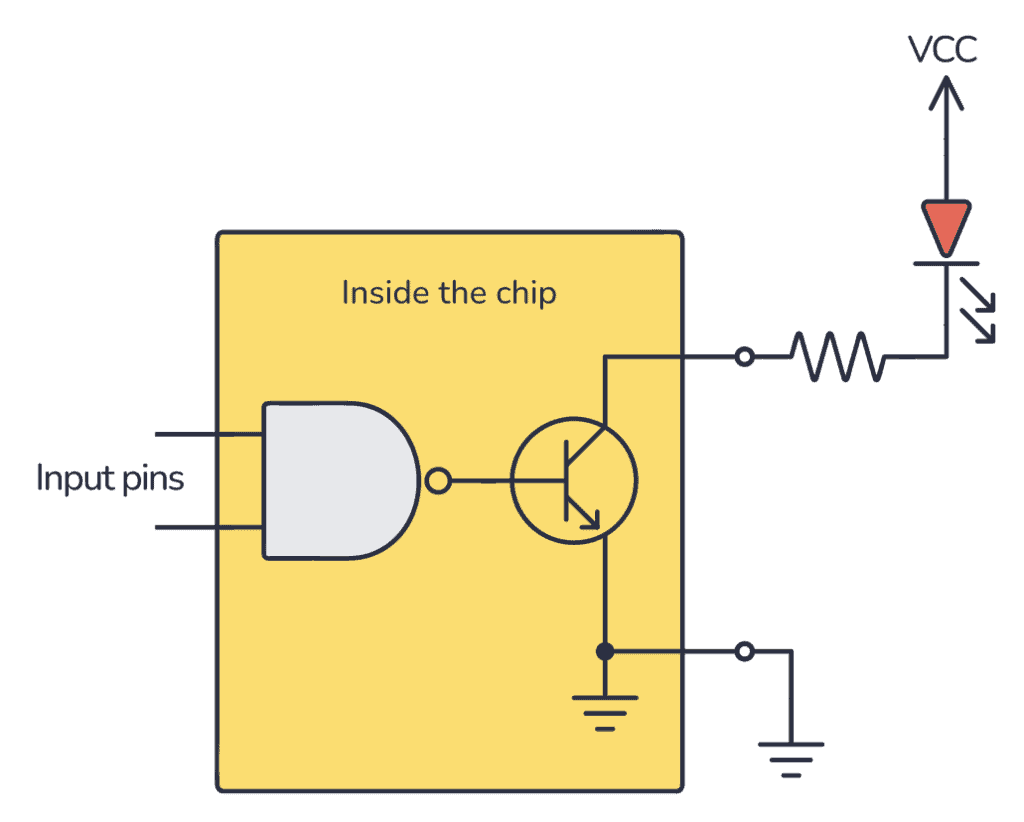
An open collector output is not a normal high/low output. Instead, these outputs are connected via a transistor. And the collector of the transistor is available at the pin. For example, if you have a NAND gate with an open-collector output, it will look like this:
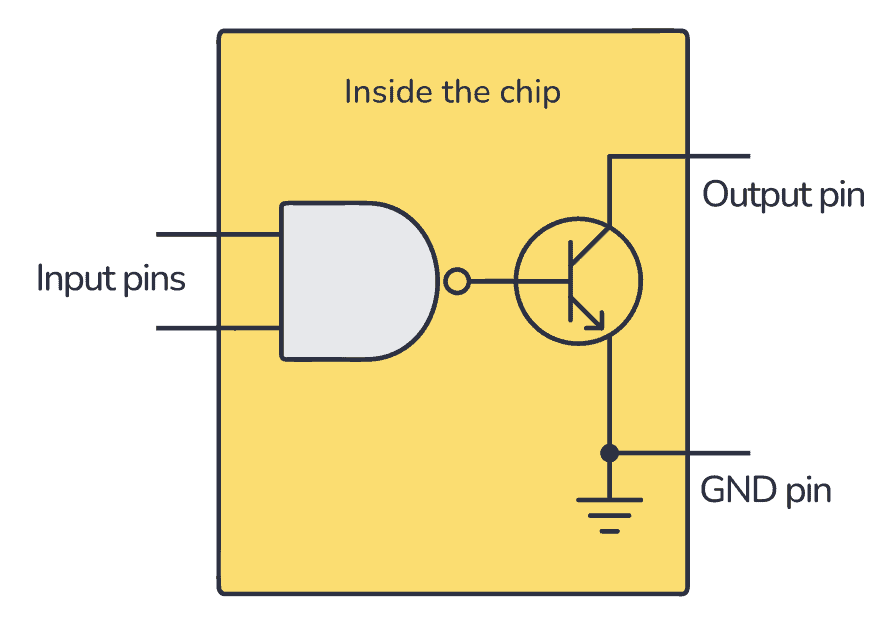
So when the output from the NAND gate is ‘1’, the transistor that is connected to the output will be turned on. When the output from the NAND gate is ‘0’, the transistor will be off.
Note: Some chips use MOSFET transistors instead of BJT. In that case, this technique is called open-drain instead, but the concept is exactly the same.
How To Use an Open Collector Output?
Here’s a simple example with an LED: To turn on the LED when the NAND gate output is ‘1’, you must connect the LED from your positive supply, via a resistor, to the open-collector output:
But if you instead want to get your standard high/low output, you could achieve this by connecting a resistor from the output up to your positive supply. Then your NAND gate output pin becomes a standard high/low output:
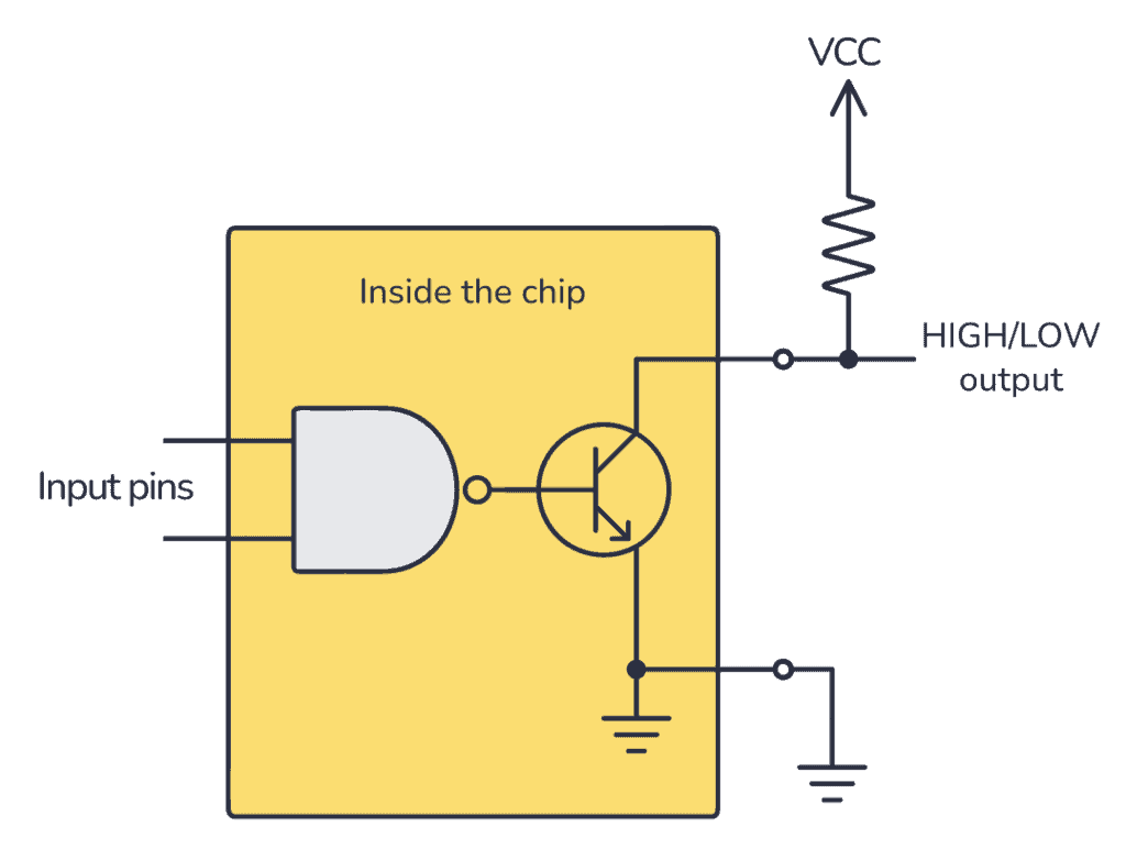
But it’s important to notice that the output will be inverted! A logical HIGH from the NAND gate turns the transistor ON so that the output voltage on the pin becomes low. A logical LOW leaves the transistor OFF so that the output voltage on the pin becomes HIGH.
The advantage of using open-collector outputs is that you can choose your HIGH voltage level to make it compatible with whatever the voltage of the next stage is. The resistor acts as a pull-up resistor and pulls the voltage up to VCC.
Where to find open collector chips?
There are several chips with open collector outputs in the 7400 series of integrated circuits. Here are a few examples:
- 74×03: An IC with four open-collector NAND gates
- 74×09: An IC with four open-collector AND gates
- 74×33: An IC with four open-collector NOR gates
- 74×136: An IC with four open-collector XOR gates
- 74×266: An IC with four open-collector XNOR gates
Copyright Build Electronic Circuits
-
CMOS (Complementary Metal Oxide Semiconductor) The main advantage of CMOS over NMOS and BIPOLAR technology is the much smaller power dis...
-
I was first introduced to logic gates when I was around 14 years old. I had heard that computers consisted of ones and zeroes. But I didn’t...
-
Do you need a MOSFET gate resistor? What value should it be? And should it go before or after the pulldown resistor? If you’re a bit impati...


