Tuesday 31 July 2018

TP4056 Lithium Ion Battery Charger

In this project, we will learn about TP4056 Lithium Ion Battery Charger which is based on the TP4056 Li-Ion Battery Charger IC. In the process, I will discuss the circuit diagram of the TP4056 Lithium Ion Battery Charger module, components on the module and how to connect an 18650 battery to this module and charge it.

WARNING: Working with batteries is extremely dangerous and if you are not familiar with the connections, results might be fatal. Battery might explode if wrongly used.

Introduction

Almost all the electronic devices and gadgets run on battery power now-a-days. You can find many devices like Mobile Phones, Tablets, Laptops, Cameras, etc. that run on battery.

Apart from the small devices mentioned above, Cars, Motorcycles, electric vehicles also contain battery and require a battery charger mechanism.

TP4056 Lithium Ion Battery Charger Module Image 1

And when a battery is involved, a Battery Charger is also involved. Battery Chargers are devices that recharge the batteries by putting energy into them.

In this project, I will talk about one such battery charger module for charging Lithium Ion Batteries. It is TP4056 Li-Ion Battery Charger.

Also read: HOW TO MAKE AN AUTOMATIC BATTERY CHARGER?

A Brief Note on TP4056 Lithium Battery Charge Controller

The TP4056 is a low-cost Lithium Ion battery charger controller IC. It supports a constant current – constant voltage charging mechanism for s single cell Li-Ion Battery.

It is available in 8-pin SOP package and requires very minimum external components in order to build a Lithium Ion battery charger circuit.

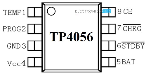
Pin Diagram of TP4056 Lithium Ion Battery Charger IC

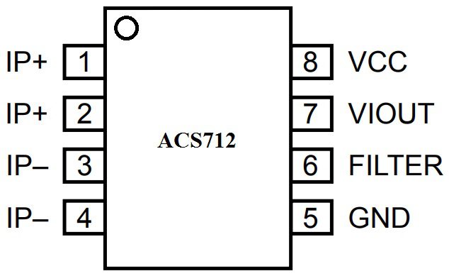
The following image shows the pin diagram of the TP4056 Li-Ion Battery Charger IC. It is an 8-pin IC and the pins are TEMP, PROG, GND, VCC, BAT, , and CE.

TP4056 Lithium Ion Battery Charger IC


Pin Number

Pin Name

Function

1

TEMP

Temperature Sense

2

PROG

Constant Charge Current Setting

3

GND

Ground

4

VCC

Supply

5

BAT

Battery Connection Pin

6

STDBY

Standby Pin

7

CHRG

Charging Pin

8

CE

Chip Enable

Pin Description

Now, let us see the description and function of each pin of TP4056 IC.

  • TEMP: It is an input pin for sensing the temperature. It is connected to the output of the NTC Thermistor in a Battery Pack. Based on the voltage at this pin, you can determine the temperature of the Battery. Battery Temperature is too low if voltage is less than 45% of VCC for more than 0.15S or it is too high if voltage is more than 80% of VCC for the same duration.
  • PROG: The charge current to the battery is set by connecting a Resistor called RPROG between this pin and GND. Based on the value of the resistor, the charge current can be anywhere from 130mA to 1000A.
  • GND: Ground Pin.
  • VCC: It is the power supply pin. TP4056 can support a maximum of 8V at VCC but typically 5V is used.
  • BAT: It is the battery connection pin connected to the positive terminal of the battery. The voltage at this pin is 4.2V.
  • STDBY: When the battery is completely charged, this pin is pulled low. An LED is connected to this to indicate standby mode.
  • CHRG: When the battery is charging, this pin is pulled low. An LED is connected to this pin to indicate battery charging.
  • CE: It is an input pin for enabling the chip into operation or disabling it. When a HIGH input is given, the TP4056 is in normal mode and when a HIGH input is given, the IC is disabled.

Controlling the Charge Current

As mentioned earlier, the PROG (Pin 2) is used to control the charge current to the battery. It is controlled with the help of a resistor called RPROG. The following table shows a list of charging current values for the corresponding RPROG values.

RPROG in KΩ

IBAT in mA

10

130

5

250

4

300

3

400

2

580

1.66

690

1.5

780

1.33

900

1.2

1000

This is calculated using the formula IBAT = (VPROG / RPROG) * 1200 and VPROG = 1V.

Circuit Diagram of TP4056 Lithium Ion Battery Charger

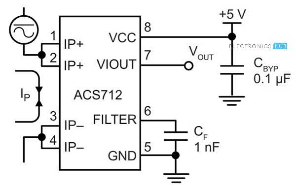
As mentioned earlier, very few external components are required for building a complete Li-Ion Battery Charger circuit using the TP4056 IC. The following image shows the circuit diagram of one such implementation.

TP4056 Lithium Ion Battery Charger Circuit Diagram

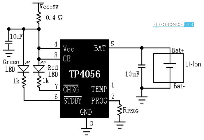
The components needed are as follows:

  • TP4056 IC
  • LEDs x 2
  • 1KΩ Resistor x 2
  • 0.4Ω Resistor
  • 10µF Capacitor x 2
  • 1.2KΩ Resistor (RPROG)

TP4056 Li-Ion Battery Charger Module

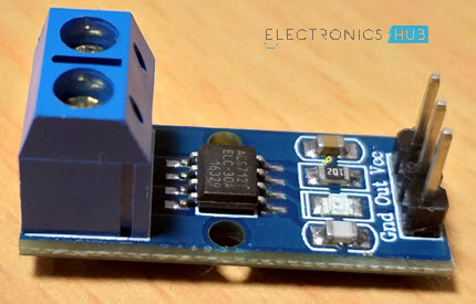
Based on the TP4056 Lithium Ion Battery Charger Controller IC and the above shown circuit diagram, several Li-Ion Battery Charger Modules are developed. The following image shows the module used in this project.

TP4056 Lithium Ion Battery Charger Module

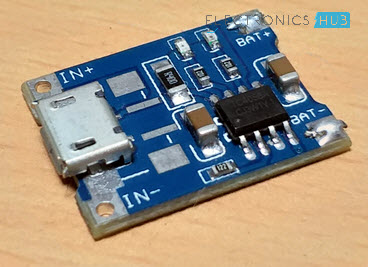
It is a tiny module with all the components mentioned in the above circuit diagram. If you notice, there is a Micro USB connector at the input side of the board. Using this, you can charge a Li-Ion battery from an USB source.

Otherwise, there are connectors for Input Voltage as well as terminals for connecting the Battery. The RPROG resistor on this module is of 1.2KΩ. Hence, this module supports a 1A (1000mA) charging current.

TP4056 Lithium Ion Battery Charger Module Components

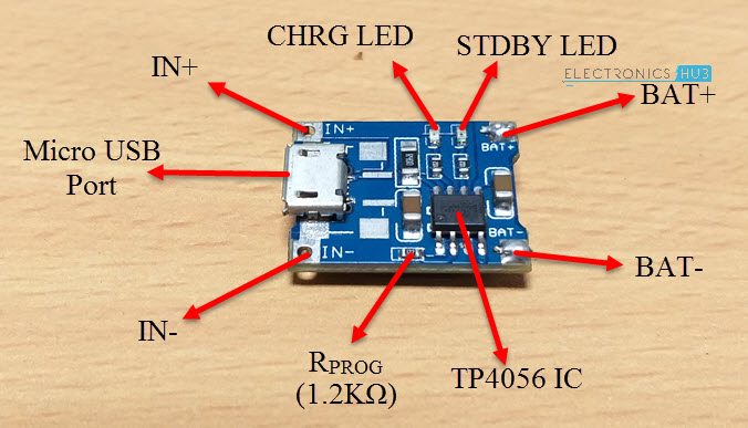
Rest of the components and parts are mentioned in the image above.

NOTE: This module and the circuit shown above doesn’t include the temperature measurement.

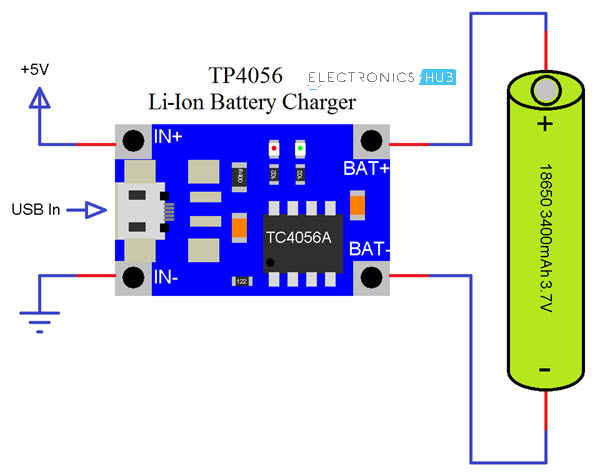
Charging an 18650 Lithium Ion Battery with TP4056

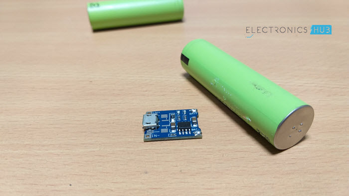
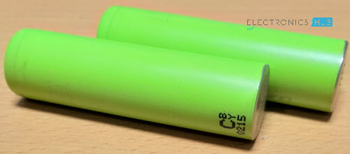
18650 Li-Ion batteries are very commonly found Lithium Ion batteries. They are used in Laptops, power banks, etc. I have dismantled an unused laptop battery and extracted three 18650 Batteries.

TP4056 Lithium Ion Battery Charger 18650 Li Ion Battery

WARNING: Dismantling laptop batteries can be hazardous. We do not recommend it.

If you have 18650 Li-Ion batteries, connect one battery as shown in the following connection diagram. You can charge only one battery at a time. In order to charge the battery, you can either use the IN+ and IN- terminals and provide 5V or alternatively, you can use an USB cable to directly charge from USB supply.

TP4056 Lithium Ion Battery Charger Connection Diagram

Applications

TP4056 Lithium Ion Battery Charger Module (or the IC) can be used in many applications like:

  • Mobile Phones
  • GPS Devices
  • Digital Cameras
  • Power Banks
  • USB Chargers
  • Handheld Computers

The post TP4056 Lithium Ion Battery Charger appeared first on Electronics Hub.

Monday 30 July 2018

3D printing the next generation of batteries

3D printing can be used to manufacture porous electrodes for lithium-ion batteries -- but because of the nature of the manufacturing process, the design of these 3D printed electrodes is limited to just a few possible architectures. Until now, the internal geometry that produced the best porous electrodes through additive manufacturing was what's known as an interdigitated geometry -- metal prongs interlocked like the fingers of two clasped hands, with the lithium shuttling between the two sides.

'Smart' machine components alert users to damage and wear

Scientists have used advanced additive manufacturing technology to create 'smart' machine components that alert users when they are damaged or worn.

Saturday 28 July 2018

Optical neural network demo

Researchers have made a silicon chip that distributes optical signals precisely across a miniature brain-like grid, showcasing a potential new design for neural networks.

How to use Hall Effect Sensor with Arduino?

In this project, we will learn about Hall Effect Sensor, how a Hall Effect IC works, block diagram of a typical Hall Effect IC and how to interface a Hall Effect Sensor with Arduino. Additionally, I will show you how to control a Relay using Hall Effect Sensor and Arduino.

Introduction

If you remember the Arduino WaterFlow Sensor Tutorial we implemented earlier, the main component of the Water Flow Sensor is the Hall Effect IC.

A Hall Effect Sensor works on the principle of, well, Hall Effect. Simply speaking, a Hall Effect Sensor or IC detects motion, position or change in magnetic field strength of either a permanent magnet, an electromagnet or any ferromagnetic material.

Interfacing Hall Effect Sensor with Arduino Relay Control 1

Hall Effect IC are contact-less magnetically activated switches. They are used in a wide range of applications like automobiles, computers, control systems, security systems etc.

So, in this project, I will discuss about a Hall Effect IC A11004, how this Hall Effect Sensor works and finally how to interface a Hall Effect Sensor with Arduino.

A Brief Note on Hall Effect Sensor

As mentioned earlier, a Hall Effect Sensor is a magnetically activated switch with non-contact trigger. The Hall Effect IC which I will be focusing on in this project is A1104 from Allegro Micro Systems. It is available in 3-pin SIP as well as SOT23 packages.

Interfacing Hall Effect Sensor with Arduino Hall Effect IC

Above image shows the A1104 Hall Effect IC used in this project. It is based on BiCMOS technology, which combines the benefits of both the Bipolar and CMOS technologies.

Block Diagram of the Hall Effect Sensor

The main components of the A1104 Hall Effect IC are: Voltage Regulator, Hall Device, Small Signal Amplifier, Schmitt Trigger and an Output NMOS Transistor. The following image shows the block diagram of this Hall Effect IC.

Interfacing Hall Effect Sensor with Arduino Hall Effect IC Block Diagram

Pins of A1104 Hall Effect Sensor

Before going to see the working of a Hall Effect IC, let me give an overview of the Pins of the A1104 Hall Effect IC. There are three pins on the A1104 Hall Effect IC: VCC, GND and OUT.

  • VCC (1): Power Supply to IC. 3.8V to 24V.
  • GND (2): Ground.
  • OUT (3): Output of the IC.

The following image shows the Pins of the A1104 Hall Effect IC.

Interfacing Hall Effect Sensor with Arduino Hall Effect IC Pins

Working of the Hall Effect Sensor

The Hall Element or the Hall Device (sometimes called as the Active Area) is a small semiconductor sheet. This is represented as the following image.

Interfacing Hall Effect Sensor with Arduino Working Hall Device

When a constant voltage is given at VCC, some small but constant current flows through the semiconductor sheet. When there is no magnetic field, the voltage VHALL, which is measured across the width of the Hall Element (semiconductor sheet) will be approximately equal to 0V.

Interfacing Hall Effect Sensor with Arduino Working No Magnet

If the Hall Element is subjected to a magnetic field such that, the magnetic flux of the magnetic field is perpendicular to the current flowing through the sheet, the output voltage VHALL is directly proportional to the strength of the magnetic field.

Interfacing Hall Effect Sensor with Arduino Working with Magnet

Types of Hall Devices

Based on the orientation and characteristics of the Active Area (Hall Element), Hall Effect Sensors can be categorized into three types.

  • Planar Hall Device
  • Vertical Hall Device
  • 3D Hall Device

In Planar Hall Devices, the flux lines of the magnetic field must pass perpendicularly through the active area to optimally operate the switch. Here, the active area is parallel to the branded face of the IC i.e. the face marked with Manufacturer part number.

Interfacing Hall Effect Sensor with Arduino Hall Effect Sensor Types

Coming to the Vertical Hall Device, its sensitive areas can be on the top edge, right side edge or left side edge. Finally, a 3D Hall Device can detect the magnetic field when the magnet is approached from any direction.

NOTE: An important point to remember about the operation of the Hall Effect Sensor is that both the magnetic field strength as well as the polarity (North or South) are equally important. The Hall Effect Sensor will switch only if it is subjected a sufficient magnetic flux density as well correct polarity.

A Hall Effect Sensor can be sensitive to either North Pole or South Pole but not both.

Interfacing Hall Effect Sensor with Arduino

Now that we have seen a little bit about the Hall Effect Sensor, let me take you through the steps of interfacing a Hall Effect Sensor with Arduino.

As usual, I will implement two circuits: one is the basic hook-up guide of Hall Effect Sensor with Arduino and the second one is an application circuit where I will control a relay with the help of Hall Effect Sensor and Arduino.

Components Required

The components required for both these circuits are mentioned below.

  • Arduino UNO
  • A1104 Hall Effect IC
  • 10KΩ Resistor
  • LED
  • 1KΩ Resistor
  • 5V Relay Module
  • Mini Breadboard
  • Connecting Wires

Hook-up Guide of Hall Effect Sensor with Arduino

The following image shows the necessary connections between Arduino UNO and A1104 Hall Effect IC.

Interfacing Hall Effect Sensor with Arduino LED Circuit Diagram

Code

Interfacing Hall Effect Sensor with Arduino LED

Working

If you notice the circuit diagram, the connections are pretty straight forward. The VCC and GND pins of the Hall Effect IC i.e. Pins 1 and 2 from the branding face are connected to +5V and GND of Arduino.

The OUT pin of the Hall Effect IC is pulled HIGH using a 10KΩ Resistor.

Whenever the magnetic field is placed near the Hall Effect IC, the output of the Hall Effect IC becomes LOW. This change is detected by Arduino and accordingly it activates the LED.

Control a Relay with Arduino and Hall Effect Sensor

The circuit diagram for controlling a 5V Relay Module with Hall Effect Sensor and Arduino is shown below.

Interfacing Hall Effect Sensor with Arduino Relay Control Circuit Diagram

Code

Interfacing Hall Effect Sensor with Arduino Relay Control

Working

The working of this circuit is very simple. Whenever the Hall Effect Sensor is subjected to a magnetic field, it toggles the Relay (as per the code).

Applications of Hall Effect Sensor

Hall Effect Sensor is used in a wide range of applications like

  • Automobile ignition systems
  • Tachometers
  • Current Sensors
  • Brushless DC Motor Controllers
  • Speed Control Systems
  • Printers
  • Keyboards
  • Switches (key and push button)
  • Security Systems
  • Position Detectors

The post How to use Hall Effect Sensor with Arduino? appeared first on Electronics Hub.

Thursday 26 July 2018

Excitons: Taking electronics into the future

Researchers have developed a transistor based on excitons -- a type of particle most people have not heard of -- that is able to function at room temperature. This breakthrough could lead to a new breed of faster, more energy efficient and smaller electronics.

Scientists unlock the properties of new 2D material

A new two-dimensional material has become a reality, thanks to scientists. The research succeeded in the first experimental realization and structural investigation of single-layer vanadium disulphide (VS2).

Arduino SD Card Module Interface – Hook-up Guide and Data Logging

In this project, I will show you what is an SD Card Module, how to interface a MicroSD Card Adapter with Arduino and how the Arduino SD Card Module Interface can be used for Data Logging of sensor data.

Introduction

We have interfaced several sensors like Humidity, Temperature, RTC Clock, etc. with Arduino in several earlier projects. All we did in those projects is hook-up a sensor with Arduino and view the sensor’s data on either an LCD or the Arduino IDE’s Serial Monitor.

As soon as you power-off the Arduino, all the previous data read from the sensor is lost and there is now way you can retrieve that data.

Arduino SD Card Module Interface Image 1

Data Logging is a process of recording data based on time or an event. Data Logging is already being implemented in several applications like Weather (Temperature), Agriculture (Soil Moisture), Automobiles (Crash Data), Aircrafts (Black Box), etc.

In our case, if we want to record the data from a sensor using Arduino, we have to interface an SD Card with Arduino. In order to do that, you have to use a MicroSD Card Adapter or an SD Card Module and understand about the Arduino SD Card Module Interface.

A Brief Note on SD Card Module / Adapter

A Micro SD Card is a flash based, removable memory device. It is non-volatile memory and is often used in mobile phones and other consumer electronic devices.

Arduino SD Card Module Interface Micro SD Card

Before going to look at the SD Card Adapter, you need to understand two things about a typical Micro SD Card.

First thing is the operating voltage. Almost all Micro SD Cards work in a voltage range of 2.7V to 3.6V (typically, 3.3V). Second, is the communication interface. A Micro SD card supports SPI Communication.

Related Post: Basics of SPI Communication

An SD Card Module or a Micro SD Card Adapter is a simple board which facilitates connection between a Micro SD card and a Microcontroller like Arduino. The following is the image of a typical SD Card Module.

Arduino SD Card Module MicroSD Card Adapter

Since Arduino operates at 5V and the Micro SD Card operates at 3.3V, a typical Micro SD Card Adapter or an SD Card Module basically consists of two important components. They are the 3.3V Voltage Regulator IC and a 5V to 3.3V Level Converter IC for the communication pins.

Pins of SD Card Module

Talking about pins, as I have mentioned that a Micro SD Card supports only SPI Communication, the SD Card Module has pins for SPI Communication. So, the pins on an SD Card Module are as follows.

  • VCC – 5V
  • GND – GND
  • MOSI – Master OUT Slave IN (Input)
  • MISO – Master IN Slave OUT (Output)
  • SCK – SPI Clock (Input)
  • CS – Chip Select (Input)

The following image shows the pins and components of an SD Card Module.

Arduino SD Card Module Pins

Arduino SD Card Module Interface

Now that we have seen a little bit about the SD Card Module, let us proceed with interfacing one with Arduino. First thing to remember is that the communication between Arduino and the SD Card Module is through SPI Interface.

Hence, you have to identify the SPI Pins on your Arduino Board. In case of Arduino UNO, the SPI Pins are as follows:

  • MOSI – 11
  • MISO – 12
  • SCK – 13
  • CS or SS – 10

If you are using Arduino Mega, then check for the SPI Pins before making the connection.

Coming to the Arduino SD Card Module Interface, I have designed two circuits for this project. In the first circuit, I have simply made the connection between the Arduino and the SD Card Module and extract the information of the card. This circuit can be considered as an Arduino SD Card Module Hook-up Guide.

In the second circuit, the magic of actual data logging happens. It is an extension to the first circuit with sensors connected to the Analog Pins of Arduino and the data from these sensors is captured on an event.

Components Required

Components mentioned here are combined for both the circuits.

  • Arduino UNO
  • Micro SD Card
  • Micro SD Card Adapter or SD Card Module
  • Push Button
  • 3 x 10KΩ Potentiometers
  • Connecting Wires

Arduino SD Card Module Hook-up Guide

The following image shows the circuit diagram of the Arduino SD Card Module Interface.

Arduino SD Card Module Interface Circuit Diagram

Circuit Design

Connect the MOSI, MISO, SCK and CS (SS) pins of the SD Card Module to Digital I/O Pins 11, 12, 13 and 10 of Arduino. Connect the VCC and GND pins of the SD Card Module to +5V and GND of Arduino.

Code

You can find the code in the Arduino IDE: File – Examples – SD – CardInfo. You can also use the following code.

Arduino SD Card Module Interface Insert SD Card

Working

Insert a Micro SD Card in the slot provided on the SD Card Module and make the necessary connections. Upload the code to Arduino and open the Serial Monitor. If everything goes well, you can see the information about your Micro SD Card on the serial monitor.

Arduino SD Card Module Interface Card Info

Everything is taken care by the SPI and SD libraries of Arduino. You don’t have to download these libraries as they come with Arduino IDE.

Data Logging with Arduino SD Card Module Interface

The next circuit is about data logging on to a Micro SD Card using the Arduino and SD Card Module. The following image shows three Potentiometers connected to three Analog pins of Arduino.    

Arduino SD Card Module Data Logging Circuit Diagram

Circuit Design

The Interface of Arduino and Micro SD Card Adapter is same as the earlier circuit. Additionally, three potentiometers are used as analog sensors and are connected to A0, A1 and A2 of Arduino UNO.

Also, a button is connected to Pin 7 of Arduino to mark an event.

Code

Working

As I have mentioned earlier, data logging happens either at a predefined interval of time or in case an event is triggered. For the first case i.e., to log the data based on time, you have to interface an RTC Module to Arduino and the data from the sensor can be updated to the log at a certain time interval.

Since this project is a simple interface between Arduino and Micro SD Card, I have not used an RTC Module but a simple Push Button.

When ever the button is pressed, Arduino captures the sensor data from the Analog Pins and writes them to a text file on the Micro SD Card.

Arduino SD Card Module Interface Data Logging

The data is also displayed on the serial monitor. To view the data, simply connect the Micro SD Card to a computer and open the text file.

IMPORTANT NOTES:

  • If your Micro SD is not being read by Arduino, make sure that it is FAT formatted. The SD library supports both FAT16 and FAT32 formats.
  • The SPI Pins MOSI, MISO and SCK are fixed but CS or SS pin can be modified. Make sure that you have selected the correct pin.   

The post Arduino SD Card Module Interface – Hook-up Guide and Data Logging appeared first on Electronics Hub.

Tuesday 24 July 2018

Blasting tiny craters in glass, creating material to miniaturize telecommunication devices

Modern communication systems often employ optical fibers to carry signals across or between devices, combining more than one function into a single circuit. However, signal transmission requires long optical fibers, which makes miniaturizing the device difficult. Instead of long optical fibers, scientists have started testing planar waveguides. Investigators now report on a laser-assisted study of a type of glass that shows promise as a material for broadband planar waveguide amplifiers.

Generation of random numbers by measuring phase fluctuations from a laser diode with a silicon-on-in

Researchers have shown that a chip-based device measuring a millimeter square could be used to generate quantum-based random numbers at gigabit per second speeds. The tiny device requires little power and could enable stand-alone random number generators or be incorporated into laptops and smart phones to offer real-time encryption.

Monday 23 July 2018

BH1750 Ambient Light Sensor with Arduino

In this project, we will learn about the BH1750 Ambient Light Sensor Module and also how to interface a BH1750 Ambient Light Sensor with Arduino to obtain the ambient light data and display is on an LCD.

Introduction

Light Sensors are one of the important features in several devices like Mobile Phones, cameras, Cars, TVs, etc. In mobile phones, the ambient light sensor is responsible for automatically adjusting the brightness of the display depending on the intensity of the light.

In cars, ambient light sensors help in automatically turning on the headlights when outdoor lighting conditions become dark.

BH1750 Ambient Light Sensor with Arduino Image 1

We have already seen few Light Sensors implemented in Electronics Hub and the simplest of all is the LDR (Light Dependent Resistor). Using an LDR is well and good if your application is very simple, like turning on a Lamp when it becomes dark.

But for complex applications like Mobile Phones, you need accurate measurement of the intensity of the surrounding light.

So, in this Arduino DiY Project, we will interface a simple Ambient Light Sensor with Arduino and extract the intensity of illuminance in lux (lx).

Also read: Darkness Detector using LDR

A Brief Note on BH1750 Ambient Light Sensor

The BH1750 Ambient Light Sensor Module is based on the digital Ambient Light Sensor IC BH1750FVI developed by ROHM Semiconductor. It is a digital IC with built-in 16-bit illuminance to digital converter.

For communication with external devices like Microcontrollers, the BH1750 Ambient Light Sensor IC uses I2C Bus Interface.

The following is the image of a typical BH1750 Ambient Light Sensor Module available today.

BH1750 Ambient Light Sensor Module

Some features of this BH1750 Ambient Light Sensor are mentioned below.

  • I2C Interface
  • Wide range – 1 – 65535 lx
  • Built-in A to D Converter where Illuminance is the Analog Input
  • Small influence of IR Radiation
  • Very minimum external components
  • Two devices can be connected on the I2C bus

Pin Configuration of BH1750 Ambient Light Sensor

The BH1750 Ambient Light Sensor Module has 5 pins on it. The following image shows the pins of this sensor.

BH1750 Ambient Light Sensor Module Pin Out

Pin Description

  • VCC – 3.3V to 5V
  • GND – GND
  • SCL – I2C Clock
  • SDA – I2C Data
  • ADD – I2C Device Address

Interfacing BH1750 Ambient Light Sensor with Arduino

By interfacing BH1750 Ambient Light Sensor with Arduino, you can measure the ambient light data and use it in any application like turning on a street light or night lamp.

Since the BH1750 Ambient Light Sensor interfaces over I2C bus, we have to use the I2C pins of the Arduino.

In case of Arduino UNO, Analog Pins A4 and A5 are the I2C Bus pins where A4 is SDA and A5 is SCL.

The output of the BH1750 Ambient Light Sensor is displayed on a 16×2 LCD Display that is interfaced with Arduino.

Circuit Diagram of BH1750 Ambient Light Sensor with Arduino

The following image shows the circuit diagram of Interfacing BH1750 Ambient Light Sensor with Arduino UNO.

BH1750 Ambient Light Sensor Module with Arduino Circuit Diagram

Components Required

  • Arduino UNO
  • BH1750 Ambient Light Sensor Module
  • 16×2 LCD Display
  • Mini Breadboard
  • 10KΩ Potentiometer
  • 330Ω Resistor
  • Connecting Wires

Circuit Design

First, connect the VCC and GND of the BH1750 Light Sensor to +5V and GND of Arduino. Then connect the SCL and SDA pins of the sensor to corresponding pins of Arduino (A5 and A4).

The ADD Pin can be left open but you can connect it to GND. This makes the ADD Pin LOW and the I2C Slave Address of the BH1750 Ambient Light Sensor becomes 0x23. This is important in programming.

NOTE: If the ADD Pin is made HIGH, the I2C slave address of the BH1750 Ambient Light Sensor will be 0x5C. So, two BH1750 Ambient Light Sensors can be connected to the same I2C Bus where one ADD Pin is made LOW and the other ADD Pin is made HIGH.

Coming to the LCD, the RS, E, D4 through D7 Pins of LCD are connected to 7 through 2 Digital I/O Pins of Arduino UNO. A 10KΩ Potentiometer is used to adjust the contrast of the display.

Code

The code for Interfacing BH1750 Light Sensor with Arduino is given below.

Working

Make the connections as per the circuit diagram and upload the above code. Arduino will try to extract the ambient light data from the I2C bus and after simple calculations, the result is displayed on the LCD.

BH1750 Ambient Light Sensor with Arduino Image 2

Applications

The BH1750 Light Sensor can be used in various applications like

  • Mobile Phones
  • LCD TVs
  • Notebooks
  • Personal Computers
  • Cars
  • Portable Gaming Devices
  • Digital Cameras and Video Recorders
  • LCD Info Displays

The post BH1750 Ambient Light Sensor with Arduino appeared first on Electronics Hub.

Friday 20 July 2018

nRF24L01 Transceiver Module

In this Arduino project, we will learn about the nRF24L01 Transceiver Module, its features, specifications and finally how to enable Arduino Wireless Communication using the nRF24L01 Transceiver Module.

Introduction

Almost all the communication in the World today is wireless (at least from the end user perspective). You can find some sort of wireless communication in a variety of applications like TV Remotes, Mobile Phones, Computers, Toys, Cars, etc.

I don’t want to go into the details of Wireless Communication but you can find related information here: WIRELESS COMMUNICATION: INTRODUCTION, TYPES AND APPLICATIONS.

We have already seen a few wireless communication based projects in Electronics Hub, which are implemented using different technologies like Bluetooth, Infrared, RF (Radio Frequency) and WiFi (IEEE 802.11).

But in this project, I will be implementing an RF based Wireless Communication project using the nRF24L01 Transceiver IC. If you recall, I have implemented RF Communication in few earlier projects using the 434MHz RF Transmitter and Receiver Modules.

RF Transmitter Receiver

The main difference between these two RF Modules is their operating frequency. The nRF24L01 uses a 2.4GHz RF frequency whereas the earlier RF Modules used 434MHz RF frequency.

There is another important difference between them: in the 434MHz RF Modules, we have two separate modules; one for Transmission (Transmitter) and the other for Reception (Receiver). But the nRF24L0 is a Transceiver IC i.e. both the transmitter and receiver are integrated on the same IC.

A Brief Note on nRF24L01 Transceiver IC

The nRF24L01 is a single chip RF Transceiver IC developed by Nordic Semiconductor. It operates in the license-free 2.4GHz ISM band (ISM – Industrial, Scientific and Medical) with support for data rates of 250kbps, 1Mbps and 2Mbps.

For data rates of 250kbps and 1Mbps, the channel bandwidth is approximately 1MHz. So, taking the minimum and maximum operating frequencies of 2400MHz and 2525MHz, you can implement a maximum of 126 RF Channels if your data rate is limited to 250kbps or 1Mbps.

In 2Mbps data rate mote, the RF channel bandwidth should be 2MHz or more to ensure non-overlapping.

nRF24L01 Transceiver Module RF Channels

There is a special feature called MultiCeiver in nRF24L01 IC. This feature enables each RF Channel with a set of 6 unique addressed data pipes so that each module can communicate with 6 other modules in the same RF Channel. 

Coming to the implementation of nRF24L01 IC, all you need is a 16MHz Crystal Oscillator, its supporting circuitry and an antenna. To design a Wireless Communication system using nRF24L01 Module, all you need is a Microcontroller, which is interfaced through Serial Peripheral Interface (SPI).

Important Features of nRF24L01 IC

  • Ultra-low power operation (26μA Standby-I mode, 900nA power down mode)
  • SPI Interface with Microcontroller
  • Integrated RF Transmitter, Receiver and Synthesizer
  • Operating voltage is 1.9V – 3.6V
  • Input pins can tolerate 5V

For more information on nRF24L01, please refer to the datasheet.

nRF24L01 Transceiver Module

Using the nRF24L01 IC, several manufacturers started developing the nRF24L0 Transceiver Module boards that contain the necessary components and pins for implementing a radio system.

The nRF24L01 Transceiver Module boards usually consists of the nRF24L01 Transceiver IC, a 16 MHz Crystal, an Antenna Trace (on the PCB), Pins for communication and power and a few passive components.

Following is the image of a typical nRF24L01 Transceiver Module board available today.

nRF24L01 Transceiver Module

IMPORTANT NOTE: The above module and almost all the latest nRF24L01 Transceiver Modules uses nRF24L01+ IC. It is an advanced version of the nRF24L01 IC and in fact, all the discussion made is the previous section is about nRF24L01+ IC.

Components on nRF24L01 Transceiver Module

The following image shows the components on a nRF24L01 Transceiver Module board.

Pins Configuration of nRF24L01 Transceiver Module

Coming to the pin configuration of the nRF24L01 Transceiver Module, it has 8 pins. They are VCC, GND, MOSI, MISO, SCK, IRQ, CE and CSN.

  • VCC: Power Supply Pin. Only 3.3V must be given.
  • GND: GND pin of the power supply.
  • SCK: SPI Clock Pin.
  • MOSI: SPI Slave Data Input Pin.
  • MISO: SPI Slave Data Output Pin.
  • IRQ: Active LOW Interrupt Pin.
  • CE: Chip Enable Pin.
  • CSN: SPI Chip Select Pin.

nRF24L01 Transceiver Module Pins

Interfacing nRF24L01 Transceiver Module with Arduino

As mentioned earlier, the nRF24L01 Transceiver Module communicates over SPI Interface. So, in order to interface an nRF24L01 Transceiver Module with Arduino, you need to use the SPI Pins of the Arduino board.

Since the nRF24L01 is a Transceiver Module, you can transmit and receive data using only one nRF24L01 Transceiver Module at one end of the communication.

So, in this project, I will implement two circuits using the nRF24L01 Transceiver Module. In the first circuit, I will show you how to enable Wireless Communication between two Arduino Boards using two nRF24L01 Transceiver Modules, in which one Arduino – nRF24L01 Transceiver Module pair acts as a Transmitter while the other Arduino – nRF24L01 Transceiver Module pair acts as a receiver.

Coming to the second circuit, I will make use of the Transceiver option of the nRF24L01 Transceiver Module and implement both the Arduino – nRF24L01 Transceiver Module pairs as both Transmitter and Receiver. 

But there is one important thing you need to do before proceeding with the Arduino nRF24L01 Transceiver Module interface.

nRF24L01 Transceiver Module Adapter

If you notice the nRF24L01 Transceiver Module, the pins are not breadboard friendly and connecting wires directly will not be an ideal setup.

To overcome this, you have two options. First one is to make a small perf board for inserting the nRF24L01 Transceiver Module on top and with breadboard friendly pins at the bottom.

The second option is to buy an adapter for the nRF24L01 Transceiver Module as shown in the following image.

nRF24L01 Transceiver Module Adapter

As you can see, the adapter for nRF24L01 Transceiver Module consists of female headers for inserting the nRF24L01 Transceiver Module and corresponding male headers for connection with other boards like Arduino.

There is also a 3.3V regulator IC on the nRF24L01 Transceiver Module adapter so that you can provide 5V to the adapter (only to the adapter with 3.3V regulator and not directly to the nRF24L01 Transceiver Module itself).

Components Required

  • Arduino UNO x 2
  • nRF24L01 Transceiver Modules x 2
  • Joystick
  • TowerPro SG90 Servo Motor
  • LED
  • Push Button
  • 1KΩ Resistor

Simple Arduino Wireless Communication using nRF24L01 Transceiver Module

Circuit Diagram

nRF24L01 Transceiver Module Basic Wireless Communication Circuit Diagram

Connections

The following is the connections made between the Arduino UNO and nRF24L01 Modules at the Transmitter end.

nRF24L01 —— Arduino

VCC —– 3.3V

GND —– GND

MOSI —– 11

MISO —– 12

SCK —– 13

CE —– 9

CSN —– 10

As I have used an Arduino UNO even at the receiver end, I have used the same connection. If you are using other Arduino Boards like Mega, check for the SPI Pins.

Code

Transmitter Code

Receiver Code

NOTE: Bidirectional Wireless Communication Between Two Arduino Boards will be updated soon.

The post nRF24L01 Transceiver Module appeared first on Electronics Hub.

Thursday 19 July 2018

Engineers develop world's most efficient semiconductor for thermal management

Working to address 'hotspots' in computer chips that degrade their performance, engineers have developed a new semiconductor material, defect-free boron arsenide, that is more effective at drawing and dissipating waste heat than any other known semiconductor or metal materials.

Moving closer to completely optical artificial neural network

Researchers have shown that it is possible to train artificial neural networks directly on an optical chip.

Future electronic components to be printed like newspapers

A new manufacturing technique uses a process similar to newspaper printing to form smoother and more flexible metals for making ultrafast electronic devices.

Interfacing ACS712 Current Sensor with Arduino – Measure Current with Arduino

In this project, we will discuss about ACS712 Current Sensor, how a Hall Effect based current sensor works and finally how to interface the ACS712 Current Sensor with Arduino.

Interfacing ACS712 Current Sensor with Arduino Image 1

Introduction

If you recall the previous Arduino project, I have discussed about measuring voltages greater than 5V with Arduino using a Voltage Sensor. In this project, we will learn about measuring current using a Current Sensor (ACS712 Current Sensor to be specific).

A Current Sensor is an important device in power calculation and management applications. It measures the current through a device or a circuit and generates an appropriate signal that is proportional to current measured. Usually, the output signal is an analog voltage.

A Brief Note on ACS712 Current Sensor

The ACS712 Current Sensor is a product of Allegro MicroSystems that can be used for precise measurement of both AC and DC currents. This sensor is based on Hall Effect and the IC has an integrated Hall Effect device.

Coming to the output of the ACS712 Current Sensor, it produces an analog voltage that is proportional to AC or DC currents (whichever is being sensed).

The ACS712 IC is available in an 8-lead SOIC package and the following image shows its pin diagram.

Interfacing ACS712 Current Sensor with Arduino ACS712 Pin Diagram

Let us now see the pin description of ACS712. The following table shows the pin number, name and description.

Pin Number

Pin Name

Pin Description

1 & 2

IP+

+ve terminals for sensing current

3 & 4

IP-

-ve terminals for sensing current

5

GND

Signal Ground

6

FILTER

External Capacitor (to set the bandwidth)

7

VIOUT

Analog Output

8

VCC

Power Supply

There are three variants of ACS712 Sensor based on the range of its current sensing. The optimized ranges are +/-5A, +/-20A and +/-30A. depending on the variant, the output sensitivity also varies as follows:

ACS712 Model

Optimized Current Range

Output Sensitivity

ACS712 ELC-05

+/- 5A

185 mV/A

ACS712 ELC-20

+/- 20A

100 mV/A

ACS712 ELC-30

+/- 30A

66 mV/A

How ACS712 Current Sensor Works?

As mentioned earlier, the ASC712 is based on Hall Effect. There is a copper strip connecting the IP+ and IP- pins internally. When some current flows through this copper conductor, a magnetic field is generated which is sensed by the Hall Effect sensor.

Interfacing ACS712 Current Sensor with Arduino Working

The Hall Effect sensor then converts this magnetic field into appropriate voltage. In this method, the input and the output are completely isolated.

ASC712 Current Sensor Application Circuit

The typical application circuit using the ASC712 Current Sensor is given in its datasheet and the following images shows the same.

Interfacing ACS712 Current Sensor with Arduino Application Circuit

ACS712 Current Sensor Module

Using one of the variants of the ACS712 IC (5A, 20A or 30A), several manufacturers developed ASC712 Current Sensor Module boards that can be easily interfaced to a microcontroller like Arduino.

The following image shows the ASC712 Current Sensor board used in this project.

Interfacing ACS712 Current Sensor with Arduino ACS712 Current Sensor

As you can see, it is fairly a simple board with only a few components including the ASC712 IC, few passive components and connectors.

This particular board consists of ASC712 ELC-30 i.e. the range of this board is +/- 30A. the following image shows the components and pins on the board.

Interfacing ACS712 Current Sensor with Arduino ACS712 Pins

Interfacing ASC712 Current Sensor with Arduino

Measuring voltages (DC Voltages) with Arduino is very easy. If your requirement is to measure less than or equal to 5V, then you can directly measure using the Arduino Analog Pins. If you need to measure more than 5V, then you can use a simple voltage divider network or a voltage sensor module.

When it comes to measuring current, Arduino (or any other microcontroller) needs assistance from a dedicated Current Sensor. So, Interfacing an ACS712 Current Sensor with Arduino helps us in measuring current with the help of Arduino.

As ASC712 can be used for measuring either AC or DC currents, Arduino can be implemented to measure the same.

Circuit Diagram of ASC712 Current Sensor with Arduino

The circuit diagram of interfacing ACS712 Current Sensor with Arduino is shown in the following image.

Interfacing ACS712 Current Sensor with Arduino Circuit Diagram

Components Required

  • Arduino UNO
  • ASC712 Current Sensor Module
  • Load (like a lamp or a motor)
  • Power supply (for load like battery)
  • 16×2 LCD Display
  • 10KΩ Potentiometer
  • 330Ω Resistor
  • Connecting wires

Circuit Design

First, the load. I have used a 12V DC Motor along with a 12V power supply. The screw terminals of the ASC712 Current Sensor Module board are connected in series with the motor and power supply as shown in the circuit diagram.

Then connect the VCC, GND and OUT of the ASC712 board to +5V, GND and A0 of Arduino.

Interfacing ACS712 Current Sensor with Arduino Image 2

Now, in order to view the results, a 16×2 LCD is connected to Arduino. Its RS, E, D4-D7 pins are connected to Digital I/O Pins 7 through 2 of Arduino.

A 10KΩ POT is connected to Pin 3 of LCD and its VCC and GND are connected to +5V and GND.

Code

Working

Make the connections and upload the code to Arduino. In the code, there is a small calculation for measuring the current.

First, assuming the VCC to ASC712 is 5V, when there is no current flowing through the IP+ and IP- terminals, the output voltage at VIOUT of ACS712 is 2.5V. This means that you need to subtract 2.5V from the voltage measured at the analog pin.

Now, in order to calculate the current, divide this value with the sensitivity of the sensor (185mV/A for 5A Sensor, 100mV/A for 20A Sensor and 66 mV/A for 5A Sensor).

The same is implemented in code as follows.

adcValue = analogRead(currentPin);

adcVoltage = (adcValue / 1024.0) * 5000;

currentValue = ((adcVoltage – offsetVoltage) / sensitivity);  

Interfacing ACS712 Current Sensor with Arduino Output LCD

Applications

The ACS712 Current Sensor can be used in various current measuring applications like:

  • Inverters
  • SMPS
  • Battery Chargers
  • Automotive Applications like Inverters, Power Steering etc.  

The post Interfacing ACS712 Current Sensor with Arduino – Measure Current with Arduino appeared first on Electronics Hub.

Monday 16 July 2018

Interfacing Sound Sensor with Arduino – Add Sound Detection to Arduino

In this project, we will learn about a new Sensor called Sound Sensor or Sound Detector. Also, I will show you how to interface a Sound Sensor with Arduino and implement a Relay control project using Arduino, Sound Sensor and a Relay Module.

Interfacing Sound Sensor with Arduino Sound Sensor LED Image 1

Introduction

I have already implemented a sound related project a while ago which is called as HOW TO MAKE A SIMPLE CLAP SWITCH. That project is based on the famous 555 Timer IC.

In this project, I will be using a different Sound Sensor (although the idea is the same), which is sensitive to sounds like loud voices, claps, snaps, thuds and taps.

We live in a World of virtual assistants with voice interactions and they even make your haircut appointments!

Implementing a sound sensor in our DIY project today may seem a little outdated but I feel that learning something new and building a project on our own is better than buying a speaker and talking with it (pun intended).   

A Brief on Sound Sensor (Sound Detector)

A Sound Sensor is a simple device that detects sound. It is simply put a Microphone with some processing circuit. Using a Sound Sensor, you can measure the intensity of sound from different sources like knocks, claps, loud voices, etc.

The Sound Sensor used in this project is shown in the image below.

Interfacing Sound Sensor with Arduino Sound Sensor Module

It consists of a microphone, a voltage comparator IC (LM393), a potentiometer, a transistor, couple of LEDS and a few other passive components (resistors and capacitors).

Pins and Components of Sound Sensor

  • Microphone
  • LM393 Voltage Comparator IC
  • NPN Transistor (marked as J6 on my board)
  • 10KΩ Resistors x 2
  • 1KΩ Resistors x 3
  • 10KΩ Potentiometer
  • 100nF Capacitors x 4
  • LEDs x 2
  • 510KΩ Resistor
  • 51KΩ Resistor

The following image will help you identify the components and pins on a typical LM393 IC based Sound Sensor Module.

Interfacing Sound Sensor with Arduino Sound Sensor Pins and Components

Schematic of Sound Sensor

If you want to understand a little bit more about the sound sensor module, then knowing the schematic is the best way to get started. There are several Sound Sensor Modules available in the market that are implemented using different ICs like LM324, LM393, LM344, LM386 etc. So, check your sound sensor for the main IC and determine its schematic.

The following image shows the schematic of the Sound Sensor Module that is implemented using LM393 Voltage Comparator IC.

Interfacing Sound Sensor with Arduino Sound Sensor Module Schematic

If you observe in the Schematic, I have pointed out where you can extract the Analog Output from the sensor. In most LM393 based Sound Sensors, only Digital Out is available i.e. when detected sound is Higher or Lower than a certain level, the output of the sensor will Low or High.

In my case, the sound sensor will produce a logic LOW when sound is detected and a logic HIGH when there is no sound.

Interfacing Sound Sensor with Arduino

As the project is about interfacing a Sound Sensor with Arduino, let us see how its done. For this, I have designed a couple of circuit where in the first circuit I will just interface the Sound Sensor with Arduino and detect the sound with the help of an LED.

Coming to the second circuit, I will control a relay with the help of sound (snap of fingers). For both the sensors, the part with interfacing of the Sound Sensor with Arduino is same but the actions after detecting the sound is different.

Also, since I have already mentioned that my sound sensor has only digital output, I will be using only the digital I/O pins of the Arduino.

Components Required

  • Sound Sensor Module
  • Arduino UNO
  • Relay Module (5V)
  • LED
  • 1KΩ Resistor
  • Connecting wires
  • Mini Breadboard

Circuit Diagram of Interfacing Sound Sensor with Arduino

Interfacing Sound Sensor with Arduino Sound Sensor Circuit Diagram

Circuit Design

Connect VCC and GND of the sound sensor to +5V and GND of Arduino. Connect the OUT pin of the Sensor to Digital I/O pin 7 of Arduino UNO. Finally, connect an LED with 1KΩ resistor to Pin 12 of Arduino.

Code

Interfacing Sound Sensor with Arduino Sound Sensor LED Image 2

Working

After making the connections and uploading the code to Arduino, snap or clap in front of the sensor. You can observe the LED connected to OUT Pin of the sound sensor as well as the Digital Pin 12 of Arduino will be active whenever it detects any sound.

Control a Relay with Sound Sensor and Arduino

Coming to the applications of sound sensor, the following is a simple circuit using Arduino, Sound Sensor and Relay module.

Circuit Diagram

Interfacing Sound Sensor with Arduino Sound Sensor Relay Circuit Diagram

Circuit Design

The only difference between the earlier circuit and this circuit is that the LED is removed and a relay module is connected to digital I/O pin 11 of Arduino.

NOTE: I have not connected any load to the relay as this is just a demonstration.

Warning: If you intend to you your relay to actually control an electrical device, be extremely careful when making the AC Mains connections.

Code

Working

Even though the implementation of the Relay control is similar to that of an LED, the internal execution is a little bit different.

After making the connections and uploading the code, make a sound like snap or clap in front of the sensor to turn ON the relay.

Make the sound once again to turn OFF the relay.

Interfacing Sound Sensor with Arduino Sound Sensor Relay Image 1

Applications

Sound Sensor can be used in various applications like:

  • Security Systems
  • Burglar Alarms
  • Device Control
  • Door Alarms

The post Interfacing Sound Sensor with Arduino – Add Sound Detection to Arduino appeared first on Electronics Hub.

Professor resolves two decades of oxide semiconductor challenges

Successful development of high-performance amorphous P-type oxide semiconductor using tellurium-selenium composite oxide.