Monday, 28 June 2021
Transient pacemaker harmlessly dissolves in body
Using the ancient art of Kirigami to make an eyeball-like camera
Transforming the layered ferromagnet F5GT for future spintronics
Sunday, 27 June 2021
Backscatter breakthrough runs near-zero-power IoT communicators at 5G speeds everywhere
Saturday, 26 June 2021
Unbroken: New soft electronics don't break, even when punctured
Recycling next-generation solar panels fosters green planet
Tuesday, 22 June 2021
Inkjet printing 'impossible materials'
Monday, 21 June 2021
Modeling a circular economy for electronic waste
New method for molecular functionalization of surfaces
Scientists develop energy saving technique paving way for a carbon neutral society
A tiny device incorporates a compound made from starch and baking soda to harvest energy from movement
Wednesday, 16 June 2021
Pioneering chemistry approach could lead to more robust soft electronics
Inkjet printing show promise as new strategy for making e-textiles, study finds
Monday, 14 June 2021
Engineers devise novel approach to wirelessly power wearable devices
Friday, 11 June 2021
Printing flexible wearable electronics for smart device applications
Thursday, 10 June 2021
Tuning the energy gap: A novel approach for organic semiconductors
Wednesday, 9 June 2021
Important contribution to spintronics has received little consideration until now
Researchers create intelligent electronic microsystems from 'green' material
Tuesday, 8 June 2021
How Does a 555 Timer Work?
The 555 timer works by using three 5 kΩ resistors to divide the supply voltage in three. Two comparators compare these voltages to the input voltage, then sets or resets a flip-flop accordingly.
Below is a diagram showing what the 555 timer looks like on the inside:

How the 555 Timer Works
At the top of the diagram above, you have three 5 kΩ transistors between VCC and GND.
These resistors divide the VCC voltage in three.
Many think that these resistors are the reason for the name “555.” But according to an interview with the inventor, it was actually chosen at random.
Below the resistors, there are two triangles. These are comparators. If the comparator input marked with + has a higher voltage than the one marked with −, the output is high; otherwise, the output is low.

The 5k resistors set fixed voltages for each of the comparators: one-third of the VCC voltage goes to the positive (+) input of comparator 1, and two-thirds of the VCC voltage goes to the negative (–) input of comparator 2.
The green box is an SR Flip-Flop. It is a simple memory device with two states: output high (flip) and output low (flop).

It has two inputs, set (S) and reset (R). S sets the output (Q) to high and R resets it to low.
Q is always the opposite of Q.
Comparator 1 checks if the voltage on the Trigger pin is below 1/3 of VCC. If it is, it sets the flip-flop so that the Output pin becomes high.
Comparator 2 checks if the voltage on the Threshold pin is above 2/3 of VCC. If it is, it resets the flip-flop so that the Output pin becomes low.
The flip-flop also controls a transistor that connects the Discharge pin to ground when the output is low.

Summary
The pins responsible for making the Output (pin 3) go high or low are the Trigger (pin 2) and the Threshold (pin 6).
The Trigger pin is responsible for setting the output high. When the voltage on the trigger pin goes lower than one-third of VCC, comparator 1 outputs high and sets the flip-flop high, which in turn sets the Output pin high.
Pin 6 is labeled Threshold; when its voltage exceeds two-thirds of the VCC, it is responsible for resetting the Output back to low.
Want to learn how to use it? Check out the 555 timer tutorial.
Copyright Build Electronic Circuits
Friday, 4 June 2021
New form of silicon could enable next-gen electronic and energy devices
The biodegradable battery
555 Timer Tutorial and Circuits
In this 555 Timer tutorial, you’ll learn how to use the 555 timer to do fun things.
One of the first things many do with it is creating a blinking light. But that’s just one simple example of the many things you can do with this chip. You can also control motors, create an alarm, create a musical instrument, and much more.
Let’s start with an overview of the pins.
555 Timer Pinout
Pin 1 Ground
This pin connects to the negative side of the battery.
Pin 2 Trigger
When this pin goes low (less than one-third of VCC), the output goes high.
Pin 3 Output
The output voltage from the chip is around 1.5 V lower than VCC when high and around 0 V when low. A 555 timer can give out only 100 to 200 mA in total. Check your chip’s datasheet for the exact value.
Pin 4 Reset
This pin resets the whole circuit. It’s an “inverted” pin, which means it resets when the pin goes low. This means the pin must be high normally so that the chip isn’t in a “reset” state.
Pin 5 Control Voltage
This pin is used to control the threshold voltage of the Threshold pin. This can be useful when you want to adjust the frequency of the circuit without changing the values of R1, R2, and C1. Sometimes you’ll see this pin connected with a capacitor (0.01 µF/10 nF) to ground; this is a way to keep any noise on it from influencing the frequency. Sometimes you’ll see it disconnected.
Note: I’ve heard from people not able to get their circuit working without this capacitor. So you can try adding a capacitor between this pin and ground if your circuit is not working.
Pin 6 Threshold
This pin sets the output back to low when the voltage goes high (above two-thirds of VCC).
Pin 7 Discharge
This pin is unconnected when output is high, and it’s connected to ground when output is low.
Pin 8 VCC Supply
This is the positive power supply pin and can take a voltage between 5 and 15 V.
Astable Mode
When the 555 Timer is in astable mode it means that the output will never be stable. The output will keep switching between HIGH and LOW forever. That means it works as an oscillator.
You can use this to blink a light, create sound, control motors, and much more!
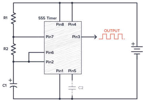
555 Timer Astable Circuit Example
Our first example is how to blink an LED with the 555 Timer. This is like the “hello world” equivalent of this IC.

Component List
This circuit is simple enough to build on a breadboard. To build it, you need the following components:
- 9V Battery
- 555 Timer IC
- R1-R3: Resistor, 1 kΩ
- LED1: Red 5mm LED or similar
- C1: Capacitor, 1000 µF
- C2: Capacitor, 10 nF (it usually works without this)
You don’t need exact values for the resistors and capacitors. But if you use the values listed above, your LED should blink about once every other second. Use the 555 Timer calculator to find the blinking frequency for other values.
Monostable Mode
Monostable means the output is stable in one state, and it will always come back to this state. You can push it out of that state, but it will always return back to its stable state after a certain time.
The output from the 555 Timer in monostable mode is normally LOW. When you trigger the circuit, the output goes HIGH for a certain amount of time before it goes back to LOW again.
This is sometimes called a one-shot circuit.
The time it stays HIGH is decided by the size of a resistor and a capacitor. The higher the values, the longer it stays HIGH.
If you connect a buzzer to the output, you can create an alarm circuit that is triggered for example by a window being opened.
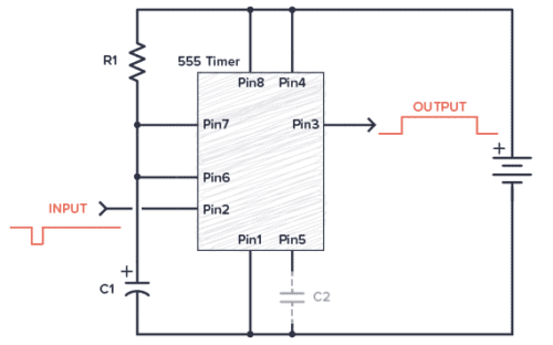
555 Timer Monostable Example Circuit
The following circuit turns on an LED when you push the button. After about 10 seconds, the LED turns off.

Component List
- 9V Battery
- 555 Timer IC
- R1: Resistor, 100 kΩ
- R2: Resistor, 5kΩ to 1 MΩ (this is a pull-up resistor)
- R3: Resistor, 1 kΩ
- LED1: Red 5mm LED or similar
- C1: Capacitor, 100 µF
- C2: Capacitor, 10 nF
- S1: Pushbutton, normally open
For longer delays, increase C1 and/or R1. If you want an adjustable delay, replace R1 with a potentiometer. Use the 555 Timer calculator to find the values you need.
The output is connected to control an LED, but could easily be modified to control a motor, a lamp, a coffee maker, or anything else. Just replace R3 and the LED with a transistor. See how in the section Driving Higher Loads below.
Bistable (Flip-Flop) Mode
Bistable means the output is stable in both states (HIGH and LOW). It will stay in one state until you push it over to the other state. Then it stays in the other state. You push it from one state to the other with the Trigger and Threshold pins.
This mode isn’t a timer function at all, and it’s not a common way to use the 555 Timer. In this mode, the 555 Timer works as a flip-flop.
You can for example use it to reverse the direction of a robot when it bumps into a wall. Or separate the ON and OFF switch for a machine.
555 Timer Bistable Example Circuit
The following example shows the 555 Timer in bistable mode. Here you have separate ON and OFF buttons to control an LED.
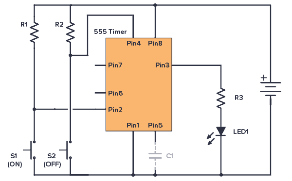
Component List
- 9V Battery
- 555 Timer IC
- S1, S2: Pushbutton, normally open
- R1, R2: Resistor, 5kΩ to 1 MΩ (these are pullup resistors)
- Resistor (R3): 1 kΩ
- LED: Red 5mm LED or similar
- Capacitor (C1): 10 nF
The output is connected to control an LED, but could easily be modified to control a motor, a lamp, or anything else by connecting a transistor. See section Driving Higher Loads below for examples.
555 Timer Output Current
The output of the 555 Timer can sink and source current of up to 200 mA.
Sourcing is when the output is HIGH and you’ve connected something from the output down to ground:
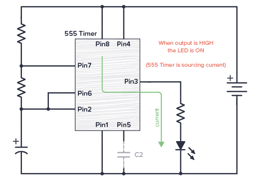
In the above circuit, the LED turns on when the output is HIGH.
Sinking is when the output is LOW and you’ve connected something from VCC to the output:
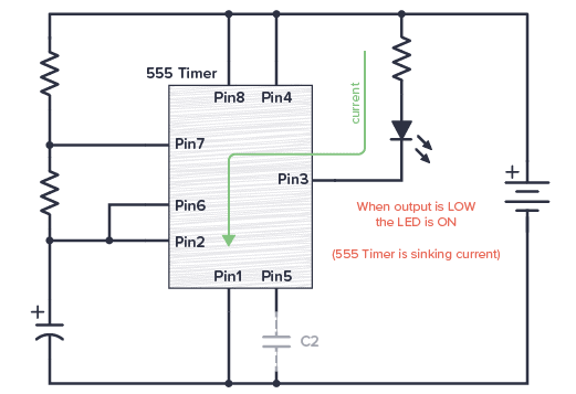
In the above circuit, the LED turns on when the output is LOW.
If you use both sourcing and sinking in your circuit, you can make a cool emergency vehicle light effect by connecting two LEDs; a blue one that is sourcing current and a red one that is sinking current.
Or how about connecting two buzzers with different frequencies to create a siren?
Circuit Example: Police Car Emergency Lights
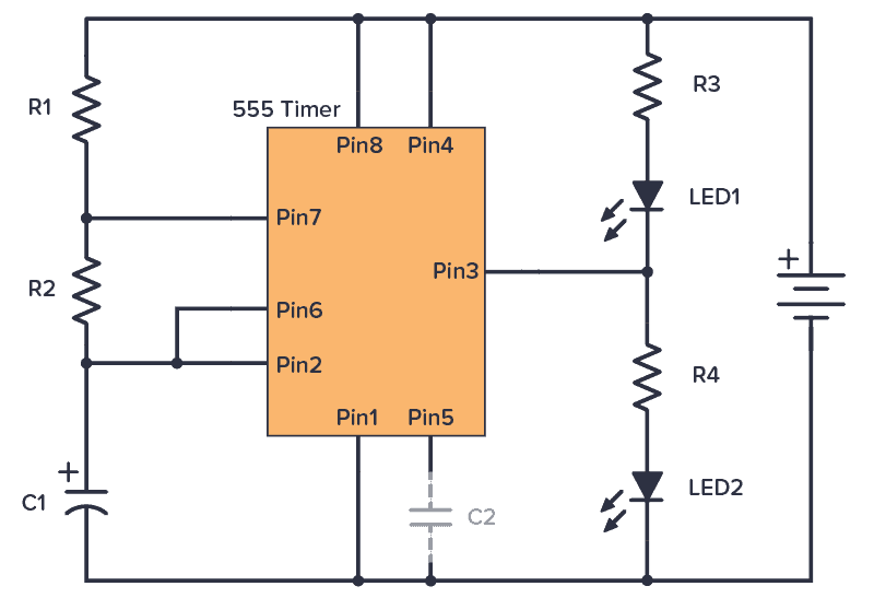
Component List
- 9V Battery
- 555 Timer IC
- R1-R2: Resistor, 1 kΩ
- R3: Resistor, 470 Ω
- R4: Resistor, 330 Ω
- LED1: Red LED
- LED2: Blue LED
- C1: Capacitor, 1000 µF
- C2: Capacitor, 10 nF (it usually works without this)
R1, R2, and C1 controls the blinking speed. R3 and R4 sets the brightness of the LEDs.
Driving Higher Loads
If you want to control motors, LED strips, or other things that need more than 200 mA of current, you can connect a transistor to the output.
If you want to use an NPN transistor, you’ll need to connect a resistor between the output and the base to limit the base current. 1 kΩ will probably work fine as a starting point.
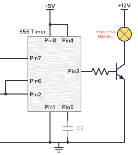
If you want to use a MOSFET on the output, you can skip the resistor. Just make sure you use a MOSFET with a VGS that is lower than the output voltage from your 555 timer.

Next Step: Build Circuits
To really learn the 555 timer you need to build some circuits. Check out these 555 Timer Circuits to get comfortable using the chip:
Do you have questions? Let me know in the comment section below!
Copyright Build Electronic Circuits