If you are new to electronics or starting to build electronic circuits, then the important thing to do is to get familiar with few Basic Electronic Components and Equipment. Without understanding these basic electronic components i.e. their values, ratings, purpose etc. your circuit design might not function as expected.
There are many electronic components like Resistors, Capacitors, LEDs, Transistors, etc. and there are also many equipment like a Power Supply, Oscilloscope, Function Generator (or Signal Generator), Multimeter, etc.
In this tutorial, you can get a brief overview of few of the most common basic electronic components. For more information about a particular component, you can check out the link associated with individual component.
Basic Electronic Components
There are many ways to classify different types of electronic components but the most common way is to classify them in to three types:
1)Active Electronic Components,
2)Passive Electronic Components and
3)Electromechanical Components.
Active Electronic Components
Strictly speaking, an Active Component is a device that acts as a source of energy, like a battery. But the definition of Active Components differs according to a few electronic engineers who perform circuit analysis. Active components are defined as the devices that depend on energy source and can introduce power into a circuit.
For example consider the diode, which is an active component. When the diode is connected to the circuit and energy source is applied, it immediately does not conduct the electrons. It starts conducting only when its threshold value is reached. Thus it depends on the energy source for its working. Hence it is an active component.
Active Electronic Components can control the flow of electrons through them. Some of the commonly used Active Components are Transistors, Semiconductors(Diodes), ICs (Integrated Circuits), Power Sources (Batteries, AC and DC Power Supplies), etc.
Diodes
A diode is a non-linear semiconductor device, that allows the flow of current in one direction. A Diode is a two – terminal device and the two terminals are Anode and Cathode respectively. The following is the symbol of a Diode.
There are again a variety of components that come under the category of Diodes. They are PN Junction Diode, Light Emitting Diode (LED), Zener Diode, Schottky Diode, Photodiode, and DIAC.
Table for different types of diodes
| Diode |
Application |
| GUNN Diode |
Used in producing microwave signals |
| Laser Diode |
Used in fiber optic communications, barcode readers ,CD/DVD drives. |
| Light emitting diode |
Using lightening applications like aviation lightening, traffic signals, camera flashes. |
| Photodiode |
Used as high voltage rectifier, photo detector, radio frequency switch. |
| Step recovery Diode |
Used for generation and shaping of high frequency pulses. |
| Tunnel Diode |
Used in microwave applications |
| Varactor diode |
Mostly used in radio frequency applications. |
| Zener Diode |
Mostly used as voltage reference diodes |
Transistors
Transistor, the invention that changed the future of electronic circuits. It is a semiconductor device that can be used to either switch electrical power or amplify electronic signals.
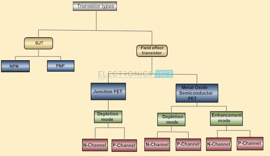
A Transistor is a 3 terminal device that can be either a current controlled device or a voltage controlled device.Different types of transistors exists.Basically they are classified as
1) Bipolar Junction Transistors (BJT) and
2) Field Effect Transistors (FET).
They can be further classified as shown below
More information on TRANSISTORS.
Integrated Circuits (ICs)
An Integrated Circuit or an IC is an integration or incorporation of several electronic components (mainly transistors) on a single device (or chip) made up of a semiconductor material (usually Silicon).
Almost all electronic devices like TVs, Mobile Phones, Laptops, Audio Players, Routers, etc. have Integrated Circuit in them.
ICs are again divided into Analog ICs and Digital ICs. Analog ICs work on Analog Signals like Temperature, Audio, etc. which are continuously varying in nature. Digital ICs on the other hand, work on Discrete Signals i.e. zero volts and a non-zero volts (like 5V or 3.3V) that are represented as Binary 0 and 1.
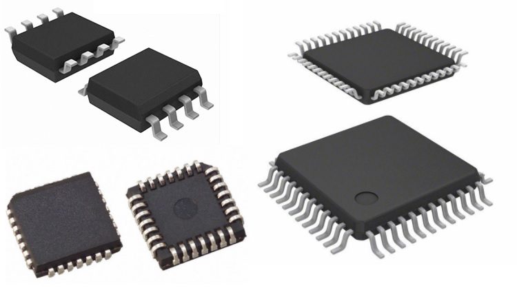
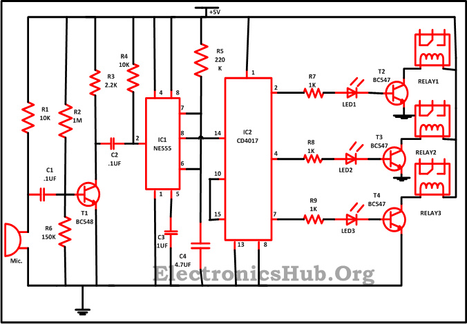
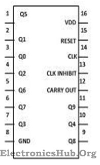
The commonly used IC in basic electronic circuits are Op – Amps (Operational Amplifiers) like LM741, Timers like NE555, Microcontrollers like AT89S52, Counters like CD4017 and Motor Drivers like L293D.
Vacuum Tubes
Before the invention of transistor vacuum tubes were used in place of transistors. This is defined as an electron tube that controls the flow of electrons in vacuum. CRT screens used in old TVs and computer monitors are best examples for vacuum tubes.
Power sources
DC Power Supply
Bench Power Supply is an important piece of equipment when it comes to working around electronic circuits. Electronic components majorly work on DC Power Supply and hence having a reliable source of DC Power Supply is very important.
There are many types of Power Supplies like AC – to – DC Power Supplies, Linear Regulators, Switching Mode Power Supply, etc.An alternative to bench power supply is to use a wall adapter as per the project requirement like 5V or 12V.
Batteries
Battery is a device that converts chemical energy in to electrical energy and provides power to devices like mobile phones, laptops, flashlights, etc. In electronics, we often use batteries to power our circuits, either to make the circuit portable or just to test the functionality of the circuit.
Batteries come in different sizes and voltage. Batteries are also classified as Primary and Secondary. You can use Primary Batteries until they are drained out and discard them later. In case of Secondary Batteries, you can use them even after they are drained out by recharging them.In electronic circuits, we often use 1.5V AA Batteries or 9V PP3 Batteries.
Display Devices
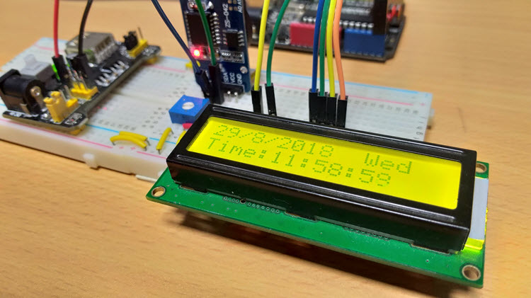
16 x 2 LCD
The most commonly used display module in electronic circuits is an LCD Display and in particular, a 16 x 2 LCD Display. It is an alphanumeric display with two rows and 16 columns and can display a maximum of 32 characters.
7 – Segment Display
Another common display module is the Seven Segment Display. It can be used to display decimal numerals in different electronic devices like clocks, meters, calculators, public information systems, etc.
Passive Components
Passive Components cannot control the flow of current through them i.e. they cannot introduce energy in to the circuit but can increase or decrease voltage and current.
These components don’t depend on the energy source for their operation.Two terminal components like Resistors, Capacitors, Inductors and transformers are examples of Passive Components.
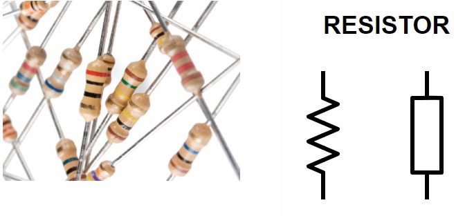
Resistors
The basic of all electronic components are the Resistors. It is a passive electronic components that introduces electrical resistance in to the circuit. Using resistors, we can reduce the current, divide voltages, setup biasing of transistors (or other active elements), etc.
Read about Resistors here: INTRODUCTION TO RESISTORS.
Ohm’s Law defines the behavior of a resistor which states that the current through a conductor is directly proportional to the voltage across the conductor. The proportionality constant is called as Resistance.
The mathematical representation of Ohm’s Law is I = V/R.
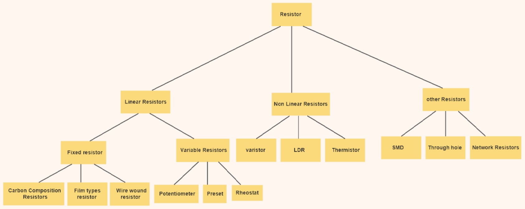
Different types of resistors can be defined according to their function,size,characteristics etc.Resistors are divided in to Fixed Resistors and Variable Resistors.
Fixed Resistors, as the name suggests, have a fixed resistance and its resistance doesn’t change due to external parameters.Variable Resistors, on the other hand, have a variable resistance that can either be changed manually or controlled by external factors like Light Dependent Resistor (LDR) or Thermistor. Below image shows different types of resistors available.

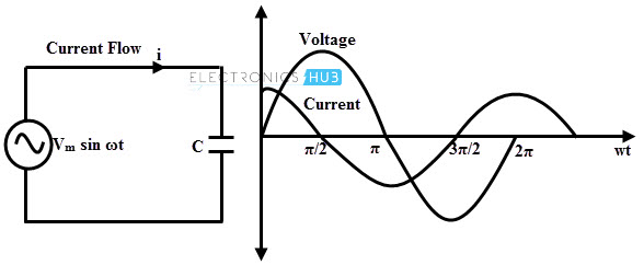
Capacitors
The second important passive components is a capacitor, a device that stores energy in the form of electric field. Most capacitors consists of two conducting plates that are separated by a dielectric material.
If Q is the charge on any one of the conductor plates and V is the voltage between them, then the Capacitance C of the Capacitor is C = Q/V.
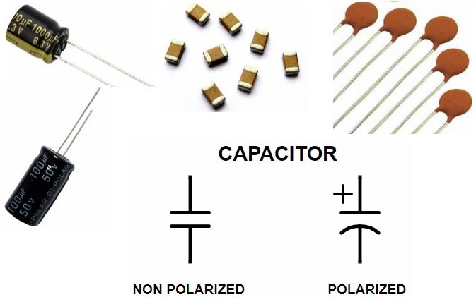
In electronics circuits, a capacitor is mainly used to block DC Current and allow AC Current. The other applications of capacitors are filters, timing circuits, power supplies and energy storing elements.
There are many types of Capacitors like Polarized, Non – Polarized, Ceramic, Film, Electrolytic, Super Capacitors etc.
Also Read INTRODUCTION TO CAPACITORS.
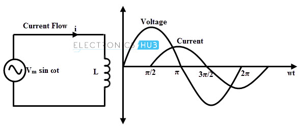
Inductors
If capacitors store energy in the form of electric field, then inductors are devices that store energy in the form of Magnetic Field. Inductor is nothing but a wire that is wound in the form of a coil.
Inductor is widely used in AC equipment like filters, chokes, tuned circuits etc.
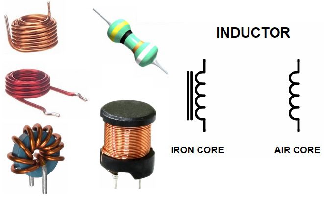
The core around which the coil is wound i.e. air, iron, ferrite etc. will determine the strength of the magnetic field. Inductors opposes the change in electric current through them and the changes in current will result in induction of voltage.
More information on INDUCTORS.
Basic Test and Measurement Equipment
When it comes to designing electronic circuits, testing and measuring various parameters like current, voltage, frequency, resistance, capacitance, etc. is very important. Hence, the Test and Measurement Equipment like Oscilloscopes, Multimeters, Logic Analyzers, Function Generators (or Signal Generators) are often used regularly.
Oscilloscope
The most reliable Test Equipment for observing continuously varying signals is an Oscilloscope. With the help of an Oscilloscope, we can observe the changes in an electrical signal like voltage, over time.
Oscilloscopes are used in a wide range of field like Medical, Electronic, Automobile, Industrial and Telecommunication Applications.
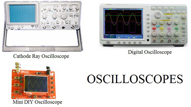
Originally, Oscilloscopes are made up of Cathode Ray Tube (CRT) displays but nowadays, almost all Oscilloscopes are Digital Oscilloscopes with advanced features like storage and memory.
Multimeter
A multimeter is a combination of Voltmeter, Ammeter and Ohmmeter. They provide an easy way to measure different parameters of an electronic circuit like current, voltage etc.
Multimeters can measure values in both AC and DC. Earlies Multimeters are Analog and consists of a pointing needle. Modern Multimeters are Digital and are often called as Digital Multimeters or DMMs.
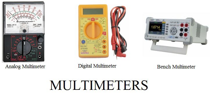
DMMs are available as handheld devices as well as bench devices. A Multimeter can be very handy in finding basic faults in a circuit.
Function Generator or Signal Generator
A Signal Generator, as the name suggests, generates a variety of signals for testing and troubleshooting electronic circuits. The most common types of signals are Triangular Wave, Sine Wave, Square Wave and Sawtooth Wave.
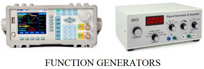
Along with a bench power supply and oscilloscope, a function generator is also an important piece of equipment when designing electronic circuits.
In this article, we have seen few Basic Electronic Components and Test Equipment that we come across very frequently when designing or testing electronic circuits.
There are a lot more components like Transformers, Buttons, Switches, Connectors, etc. which we can explore as we move forward with a project.
The post Basic Electronic Components appeared first on Electronics Hub.
 The other day, a customer sent me a question: