Monday, 30 April 2018
Water-repellent surfaces can efficiently boil water, keep electronics cool
Friday, 27 April 2018
A simple method etches patterns at the atomic scale
Cell membrane inspires new ultrathin electronic film
Thursday, 26 April 2018
New breath and urine tests detect early breast cancer more accurately
Precision optical components created with inkjet printing
Wednesday, 25 April 2018
Emerging memory devices used to develop electronic circuits for cybersecurity applications
Switch controls light on a nanoscale for faster information processing
Tiny frequency combs are reliable measurement tools
3-D print electronics and cells printed directly on skin
Cheaper and easier way found to make plastic semiconductors
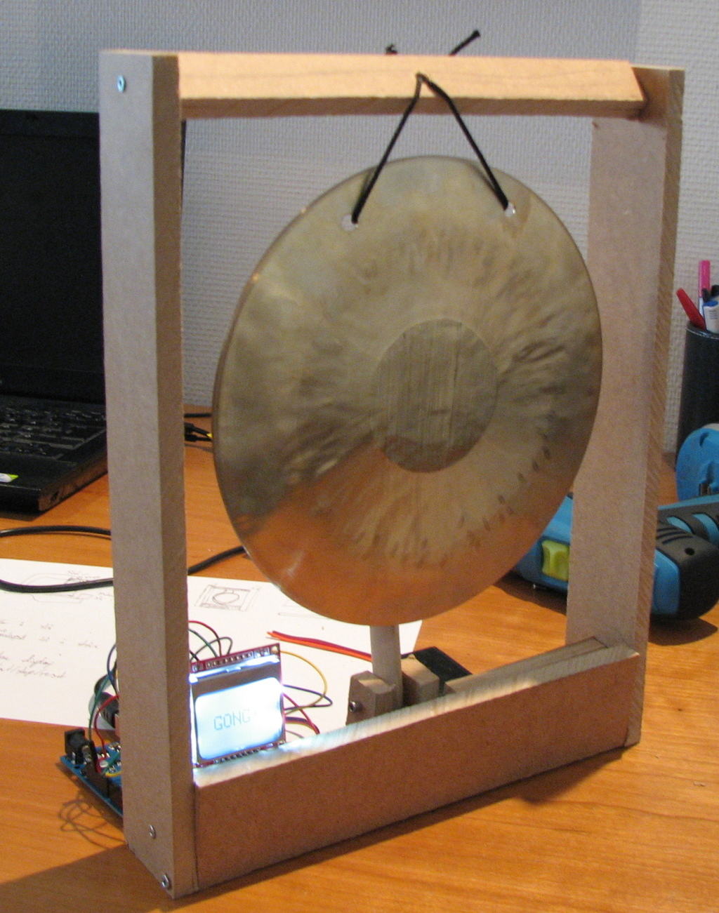
Playdate with Captain Credible
 Yesterday I met up with Captain Credible who is a musician known for his violently eccentric live performances and arsenal of homemade instruments.
We created some really cool circuits together for creating sound.
Have you ever seen the blinking the LED circuit based on using an inverter?
Here it is:
https://www.build-electronic-circuits.com/wp-content/uploads/2014/04/blinking-LED-circuit-schmitt-inverter.png
This circuit is one of the easiest ways to blink an LED.
But you can make sound with it also!
And that’s what we did yesterday.
The resistor R1 and the capacitor C1 are what sets the “blinking speed”.
By using a capacitor of 0.1µF, the “blinking speed” becomes really fast.
Too fast to see the blinking.
But connect a speaker instead, and you’ll hear sound!
That was the basis circuit, and we created lots of ways to mess around with the sound and create some really cool effect.
We decided to meet up again next Monday and continue the project.
I’ll upload a video of our two meetings after Monday.
The blinking LED circuit is part of my eBook and kit called 9 Circuits:
https://ohmify.com/get9circuits/
And with the parts that come with the kit, you can modify the circuit into creating sound like we did yesterday.
Keep On Soldering!
Oyvind @ build-electronic-circuits.com
Copyright Build Electronic Circuits
Tuesday, 24 April 2018
Getting electrons to move in a semiconductor
Sunday, 22 April 2018
4 ideas to make your first project a success
 Have you built your first project yet?
Even if you have, here are four ideas to help you make your next project a success.
1. Get your project out on a piece of paper
Getting ideas down on paper is really helpful for getting clear about what you want to do.
I like to draw boxes to represent different parts of the project.
And lines to connect them.
But other times I just write and ramble on about the project to organize my ideas and get clear.
2. Break larger designs into smaller pieces
If you want to build a walking robot that can mow your lawn, cook and solve your math homework – that’s a huge project.
If this is your first project and you want to increase your chances of success from 0.00001% to 90%, you better break this project down into pieces.
Maybe start with a super simple robot that follows the light?
(Here’s a course for that btw:
https://learn.ohmify.com/p/build-your-first-robot)
Once you’ve succeeded in the small project, go to work on the next piece.
3. Use modules to get to a working prototype faster
This is awesome for beginners.
(And also for experienced folks)
Modules are pre-assembled mini-circuits that do a specific function.
Like sending audio wirelessly.
So instead of building a radio from scratch – use a radio module!
Instead of building a motor-controller from scratch – use a motor-controller module!
4. Don’t let getting stuck stop you
When you get stuck on a project, it’s easy to avoid it.
Maybe you even start a new project to distract you from the fact that you are avoiding your original project.
Getting stuck is part of the game.
I’ve gotten stuck so many times, thinking “This is impossible!”.
But after a good night’s sleep, or a couple of days of, I attack the problem again with renewed energy.
And I always find a solution.
The most secure way of succeeding with your first project is having easy-to-follow instructions. My course Build Your First Robot is a course that shows you step-by-step how to build a simple light-following robot:
https://learn.ohmify.com/p/build-your-first-robot
Keep On Soldering!
Oyvind @ build-electronic-circuits.com
Copyright Build Electronic Circuits
Saturday, 21 April 2018
Electrochemical tuning of single layer materials relies on defects
Researchers design 'soft' robots that can move on their own
Path to a new era of microelectronics
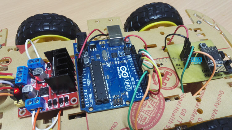
WiFi Controlled Robot using ESP8266 and Arduino
In the previous ESP8266 Projects, we have seen a few WiFi based projects like WiFi Controlled LED and WiFi Controlled Relay. Taking the same concept to a next level in this project, I will show you how to build and develop a WiFi Controlled Robot using ESP8266 and Arduino. When I say WiFi Controlled Robot, I mean a robotic car that is controlled over a WiFi Network.
Overview
If you are following ElectronicsHub for some time, you will remember that we have built a variety of robots like Line Follower Robot, Obstacle Avoiding Robot, Bluetooth Controlled Robotic Arm and RF Controlled Robot.
The first two robots i.e. Line follower Robot and Obstacle Avoiding Robot do not have any manual control of the robot i.e. there will be no additional inputs from the user apart from programming its main functionality.
But in case of the other two robots i.e. Bluetooth Controlled Robotic Arm and RF Controlled Robot, the robots wait for the user to provide appropriate input. This input can be either direction of movement or holding an object etc.
In this project, I have built a simple Robot (robotic car) that can be controlled over WiFi Network i.e. the user inputs for direction of the movement of the Robot are provided through the WiFi (with the help of a simple HTML Page).
Concept behind WiFi Controlled Robot
If you have followed our “WiFi Controlled LED using ESP8266 and Arduino” project, then you can easily understand the concept of the WiFi Controlled Robot.
The ESP8266 Module is responsible for connecting to the WiFi Network and also acting as a server. Coming to the client, a simple HTML page is created and the browser which opens this web page acts as a client.
When ever you click on the web page, corresponding information will be transmitted to the Server (ESP8266). This information is further received by Arduino and it controls the motors of the robot.
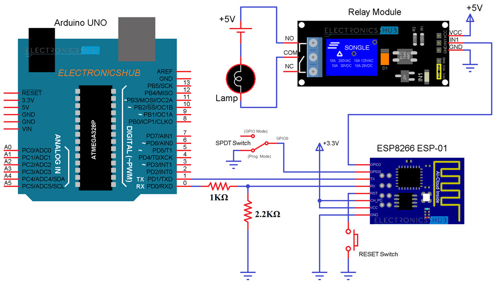
Circuit Diagram of WiFi Controlled Robot
The circuit diagram of the WiFi Controlled Robot using ESP8266 and Arduino is given in the image below.
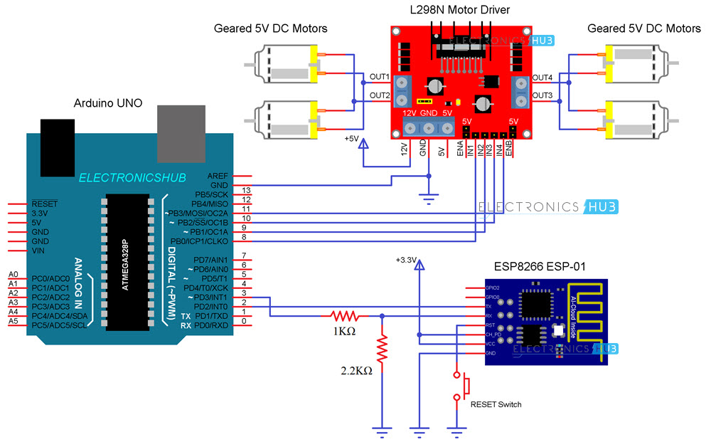
NOTE: ESP8266 WiFi Module is loaded with AT Commands. The above circuit is designed keeping that in mind.
Components Required
- ESP8266
- L298N Motor Driver Module
- Arduino UNO
- Robot Chassis
- 4 x 5V Geared Motors
- Connecting Wires
- Power supply (or battery)
Circuit Design
The first important thing to remember is that I will be programming the Arduino and it is responsible for configuring the ESP8266 Module through Serial Communication and also controlling the L298N Motor Driver Module.
So, the Digital Pins 2 and 3 of Arduino are configured as RX and TX using SoftwareSerial function. These pins are connected to the TX and RX pins of the ESP8266 Module.
Then, the Inputs of the L298N Motor Driver Module i.e. IN1, IN2, IN3 and IN4 are connected to Digital Pins 8, 9, 10 and 11 of Arduino UNO.
Coming to the robot chassis, it has 4 geared motors. So, I have connected the right two motors in parallel and connected them to OUT1 and OUT2 terminals of the Motor Driver. Similarly, the left two motors to OUT3 and OUT4.
Code
There are two codes for the WiFi Controlled Robot project. One code is for the Arduino UNO and the other is an HTML Code for creating a Web Page.
Arduino Code
Following is the Arduino Code for the project. In this code, enter the SSID and Password of your WiFi network at appropriate places.
Also, there is a section in the code which is responsible for assigning a static IP Address to the ESP8266 Module. This IP Address (along with the default Gateway and Subnet Mask) must be changed as per your requirement.
It is very important that the Static IP Address you will be assigning should not be in conflict with any other device in your network i.e. no other device should possess the same IP Address.
So, scan for all the IP Addresses in your network and carefully assign the IP Address.
HTML Code
In order to create a control web page, you can use the following HTML Code along with a JavaScript file.
Download the above code with .html extension and also download the jQuery.js file. Place both these files in a single folder.
Working
A simple project called WiFi Controlled Robot using ESP8266 and Arduino is implemented here. Let me explain its working.
Upload the Arduino code after making the necessary connections and changes to the code. If you open the serial monitor of the Arduino IDE, you can see the AT Commands that being sent to the ESP8266 Module.
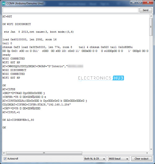
After the ESP Module is connected to WiFi, it will assign the static IP and also creates the server. Once the server is created, the ESP Module is waiting for connecting with a client.
Now, if you open the HTML Page which you have downloaded earlier, you can a simple layout that consists of five buttons with names FORWARD, REVERSE, RIGHT, LEFT and STOP.
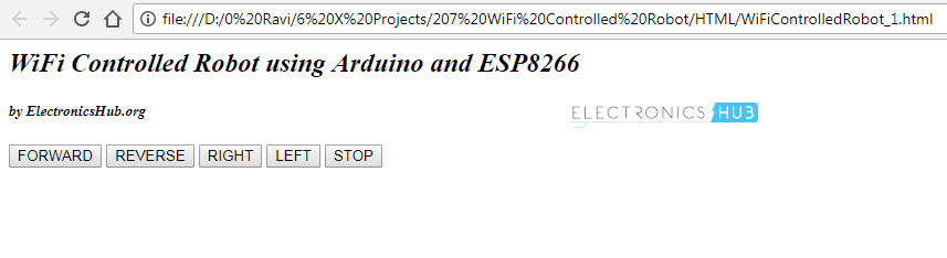
By looking at these buttons, you might have understood what each button does. Simply clicking the button performs that particular action. It is as simple as that.
NOTE:
- This WiFi Controlled Robot is controlled with the help of an HTML Web Page (which can be accessed using any web browser on a computer that is connected to the same WiFi Network as ESP8266).
- There are many projects out there which have implemented a similar concept but using Apps like Blynk.
- The reason for which I have not gone with that App is that I felt that you really do not know what is going on actually as everything is done by the library files.
- So, if you want to know exactly what is going on with the project, then only you should try this. If not, you can simply implement the project using the Blynk App.
- If you go through both the codes carefully, you can understand how the communication happens between the Browser and the ESP Module.
Conclusion and Applications
- A simple WiFi Controlled Robot is implemented in this project where a robotic car is controlled using a web page over WiFi Network.
- You can make this project with advanced features like integrating a camera and accessing the feed live on the browser.
The post WiFi Controlled Robot using ESP8266 and Arduino appeared first on Electronics Hub.
Friday, 20 April 2018
Rare earth magnet recycling is a grind -- this new process takes a simpler approach
Thursday, 19 April 2018
Integrating optical components into existing chip designs
I have a playdate!
 I met Captain Credible today.
He’s a Norwegian musician and electronics enthusiast.
And he is definitely something out of the ordinary (in a good sense).
Just watch a few seconds of his performance and you’ll understand that he’s doing things differently:
https://www.youtube.com/watch?v=TdNpwHvEVk8
He makes a lot of homemade circuits for creating music.
And he also does workshops where he teaches this.
Since we both love electronics and doing workshops, we decided to meet up and play with electronics together next week.
The topic:
Make music with simple electronic circuits.
Maybe we decide to create some crazy/interesting/out-of-the normal workshop together…
I am sure the experience will result in some videos, articles, emails or tutorials.
But no matter what:
I know it will be a fun day.
Who could you have an electronics playdate with? A colleague? A son or daughter? Grandson/daughter?
You don’t need a lot.
For example a soldering kit.
Or a circuit diagram and the components to build it.
Invite the chosen one and have some fun!
Don’t have anything to build? I’ve written an eBook with nine circuit-projects that can be done even by complete beginners. It comes with a component kit with all the components you need.
Learn more about 9 Circuits here:
https://ohmify.com/get9circuits/
Keep On Soldering!
Oyvind @ build-electronic-circuits.com
Copyright Build Electronic Circuits
Wednesday, 18 April 2018
Robot developed for automated assembly of designer nanomaterials
Flexible TVs and high performance wearable smart tech one step closer
DS18B20 Temperature Sensor with ESP8266 and ThingSpeak
In the previous project, I have shown you how to interface DHT11 Humidity Sensor with ESP8266 and post the information on ThingSpeak API. Continuing this ESP8266 – ThingSpeak Series, in this project, I will show you how to Interface DS18B20 Temperature Sensor with ESP8266 and ThingSpeak API.
Overview
Temperature Sensors are an integral part many systems like Automobiles, Computers, Air Conditioners, Printers, etc. They are also an important part of Home Security and Home Automation Systems.
Focusing on the Home Automation part, Temperature Sensors, like DS18B20, can be used in IoT Weather Stations, which is again a combination of different sensors. Upon implementing a Weather Station, you need to monitor the data in order to take necessary actions.
Here comes the combination of ESP8266 and ThingSpeak. Using ESP8266, you can connect your Weather Station to the Internet and using ThingSpeak API, you can monitor the data from the Weather Station remotely i.e. from any Web Browser.
Before implementing a complete IoT Weather Station, we will see how to Interface a DS18B20 Temperature Sensor with ESP8266 and ThingSpeak.
A Brief Note on DS18B20 Temperature Sensor
I have already shown you how to interface DS18B20 Temperature Sensor with both Arduino and Raspberry Pi. If you are interested in those projects, you can have a look: RASPBERRY PI DS18B20 TUTORIAL and ARDUINO DS18B20 INTERFACE TUTORIAL.
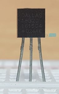
Coming to the sensor, DS18B20 is a Digital Thermometer which can measure temperatures in the range of -55 0C to +125 0C. The communication between the DS18B20 Sensor and the Microcontroller is through 1-Wire Communication (1-Wire Bus).
The most commonly used package of the DS18B20 Temperature Sensor is TO-92 Package and its Pin Diagram is shown below.
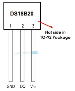
This sensor is frequently used in thermometers, thermostats, consumer electronics and industrial control systems.
Interfacing DS18B20 Temperature Sensor with ESP8266 and ThingSpeak
In this project, I’ll interface the DS18B20 Temperature Sensor with ESP8266 WiFi Module and after obtaining the data from the sensor, I’ll post Temperature information on the ThingSpeak API.
The ESP8266 Module is responsible for all the calculations and even posting the results to ThingSpeak.
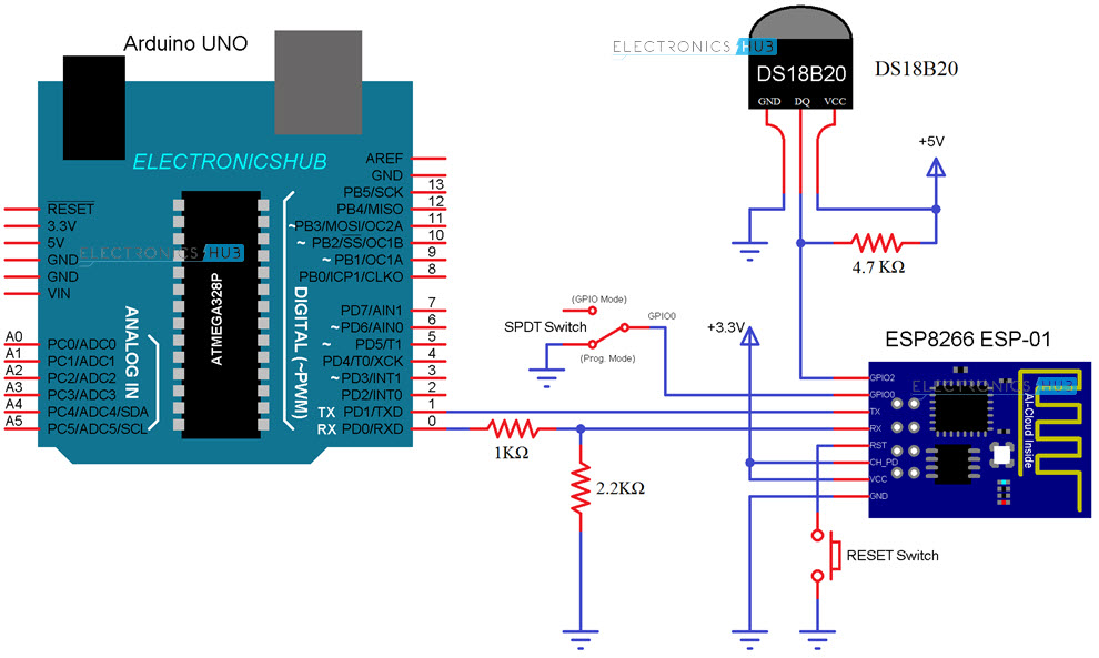
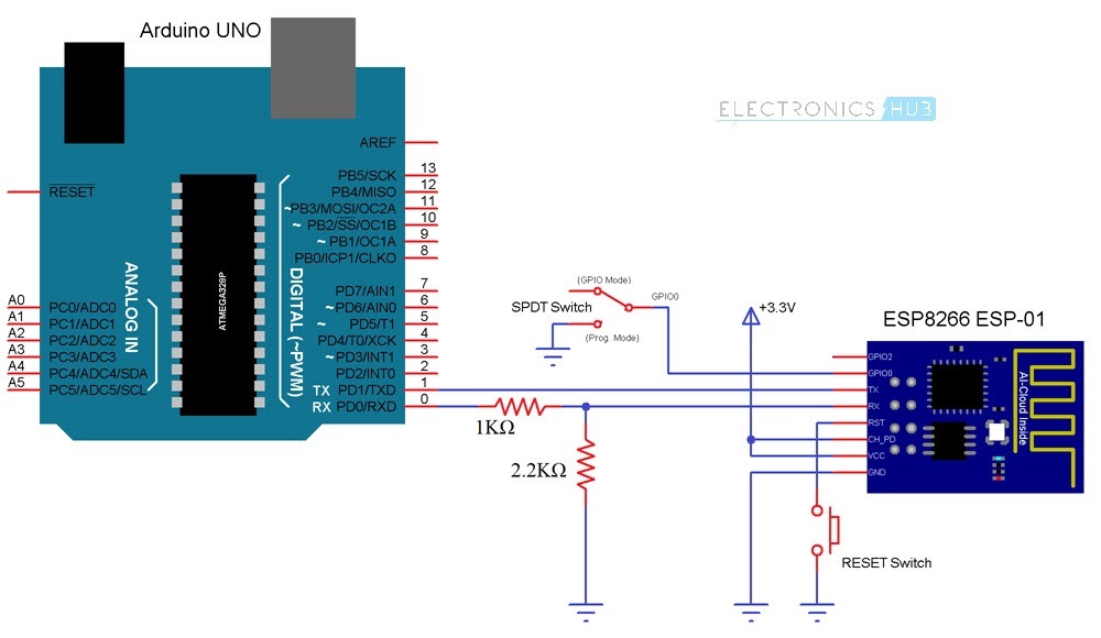
Circuit Diagram
The image below shows the circuit diagram of Interfacing DS18B20 Temperature Sensor with ESP8266.
Components Required
- DS18B20 Temperature Sensor
- ESP8266 Module
- Arduino
- 4.7 KΩ Resistor (for pull-up)
- 1 KΩ and 2.2 KΩ Resistors (for level converter)
- Connecting Wires
- Mini Breadboard
- SPDT Switch
- Push Button
Circuit Design
All the connections with respect to Arduino, which is being used as an USB-to-Serial Converter and ESP8266 Module are already explained several times in the previous projects.
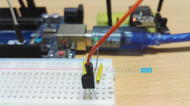
Coming to the DS18B20 Sensor, its data pin must be pulled high using a 4.7 KΩ Resistor. This data pin is connected to the GPIO2 of the ESP8266.
NOTE: I have connected a 1.5 KΩ Resistor as pull-up.
Code
Following is the code for interfacing DS18B20 Temperature Sensor with ESP8266. If you observe the code, it is very similar to the one written for Interfacing DHT11 Humidity Sensor with ESP8266.
Do not forget to change the SSID, Password and API Key as per your requirement. Also, make sure that you have downloaded the libraries OneWire and DallasTemperature.
Working
In this project, by Interfacing DS18B20 Temperature Sensor with ESP8266, I am extracting the temperature information from the sensor. Let me explain how this works.
After making all the connection as shown in the circuit diagram, configure the ESP8266 Module in Programming Mode (by connecting GPIO0 to GND and Resetting the Module). Now, you can upload the code to the ESP8266 Module using Arduino IDE.
NOTE: Select correct board and PORT in the Arduino IDE. Generic ESP8266 Module should be the Board.
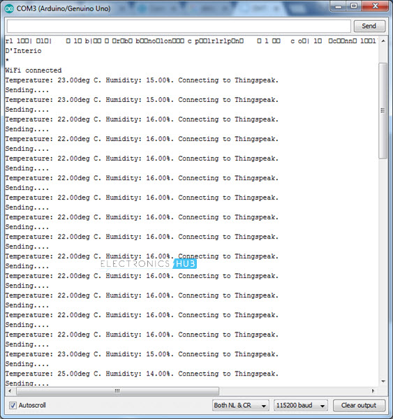
Once the code is uploaded, configure the ESP8266 is normal mode by sliding GPIO0 from GND and resetting the module. Open the Serial Monitor in the Arduino IDE and select the baud rate as 115200. Also, do not forget to choose “Both NL & CR” option.
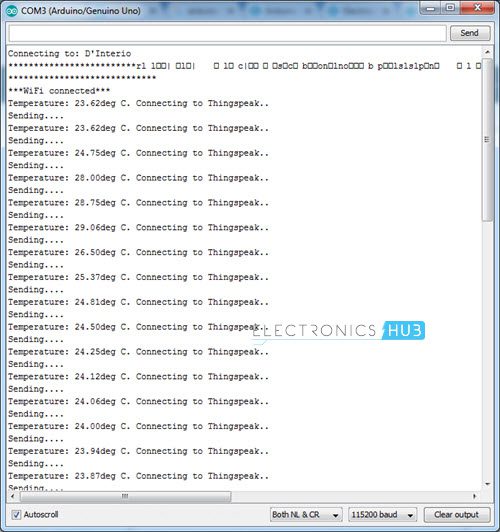
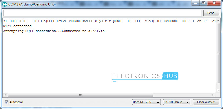
In the serial monitor, you can see the ESP8266 Module getting connected to the Internet through the WiFi Network.
After confirming the WiFi Connection, the ESP Module will start reading the Temperature information from the DS18B20 Sensor. This temperature information is displayed on the serial monitor.
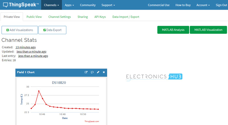
As we are also interested in monitoring the Temperature remotely, the temperature values will be uploaded to the ThingSpeak API on your channel.
In order to view the results, open your ThingSpeak Channel in any web browser and in the private view tab, you can see the Temperature values being updated.
Conclusion and Applications
- In the previous and this project, I have shown you interfacing two sensors i.e. DHT11 Humidity Sensor and DS18B20 Temperature Sensor with ESP8266.
- Also, the values (or results) from these sensors are posted in the ThingSpeak API for remote monitoring.
- These two sensors along with a few other sensors, can be implemented in a IoT based Weather Station Project.
The post DS18B20 Temperature Sensor with ESP8266 and ThingSpeak appeared first on Electronics Hub.
Tuesday, 17 April 2018
New tool speeds up the design of wearable tech
Coding and coffee
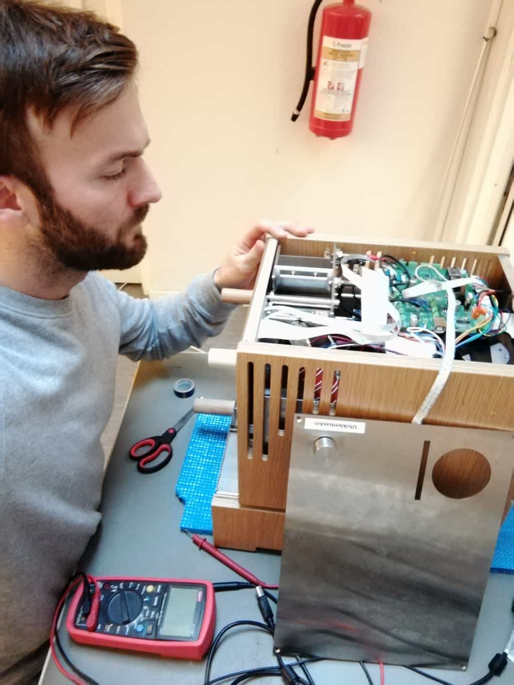 I am a coffee lover.
And these days, I am surrounded by the smell of coffee almost every day.
But no – I am not working from cafes these days (even though I love that too).
The thing is that I am hired to help with the electronics of the Norwegian coffee roaster Roest.
Since the electronics design is finished, I have been working a lot with firmware coding.
It’s something I really love doing.
And it’s so cool when I can write improvements to the code, then seconds later upload it to the machine, roast some coffee, and see the results.
The ability to write commands to a machine then instantly see the machine do what I told it to do, that’s one of those amazing things here in life.
It’s something really special.
And I think that since you are reading this, you understand what I am talking about.
Even if you are not into coding, but prefer soldering components to make some kind of gadget work – you probably know the feeling.
The whole reason for having this newsletter is to help you build what you want in electronics.
So I’ve put together a course bundle that will help you learn to code firmware for the Arduino.
Why the Arduino?
It makes it really easy to get started with microcontrollers.
You’ll find the course bundle here:
https://learn.ohmify.com/p/getting-started-with-arduino-bundle/?product_id=612624&coupon_code=TWENTYFIVEOFF
And you’ll get 25% off until the end of April with the code TWENTYFIVEOFF
NOTE: If you are an Ohmify-subscriber, you already have access to these courses. You’ll find them under “My Courses” in the top menu.
Keep On Soldering!
Oyvind @ build-electronic-circuits.com
Copyright Build Electronic Circuits
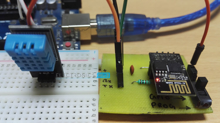
DHT11 Humidity Sensor with ESP8266 and ThingSpeak
In the previous project, I have shown you how to connect ESP8266 to ThingSpeak. After that initial setup, you can proceed with integrating various sensors with ESP8266 and monitoring the data on ThingSpeak API. So, in this project, I’ll show you how to interface DHT11 Humidity Sensor with ESP8266 and ThingSpeak and monitor the data.
Overview
DHT11 is a low-cost Humidity and Temperature Sensor. Since it has both the temperature and humidity sensors, the DHT11 Sensor is sufficient to implement your first IoT Weather Monitoring System.
When it comes to IoT, the combination of ESP8266 and ThingSpeak is an excellent way for beginners and hobbyists to dive into your IoT related projects.
If you are planning to build your own weather station, then this project could be your first step in that path. In this project, I’ll talk about the DHT11 Sensor in brief and also explain how to interface the DHT11 Humidity and Temperature Sensor with ESP8266 and ThingSpeak.
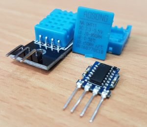
A Brief Note on DHT11 Sensor
DHT11 and DHT22 are a pair of cheap but efficient Humidity Sensors which can measure Relative Humidity and Temperature. Out of these two, the DHT11 Sensor is a cheaper version with a fairly good range of both Humidity and Temperature.
The Relative Humidity range of DHT11 is 20-95% with an accuracy of +/- 5%. Coming to the Temperature, the range is 0-500C with an accuracy of +/- 20C.
DHT22 Sensor has a wider range for both Humidity and Temperature with more accurate results but is costlier and bulkier than DHT11.
Both these sensors use a single pin for communication using 1-Wire Bus between the Microcontroller and the Sensor. The output from this single data pin is digital and hence, you don’t need an Analog Input pins on the Microcontroller. This is very useful as the ESP8266 ESP-01 Module doesn’t have any Analog Input Pins.
Interfacing DHT11 Humidity Sensor with ESP8266 and ThingSpeak
I’ll interface the DHT11 Sensor with ESP8266 through one of the GPIO Pins. All the calculations regarding the Humidity and Temperature will be performed in the ESP8266 Module.
After measuring the Temperature and Humidity, the results will be posted on the ThingSpeak API and can be seen as a graph.
Circuit Diagram
The circuit diagram for Interfacing DHT11 Humidity Sensor with ESP8266 and ThingSpeak is shown in the image below.
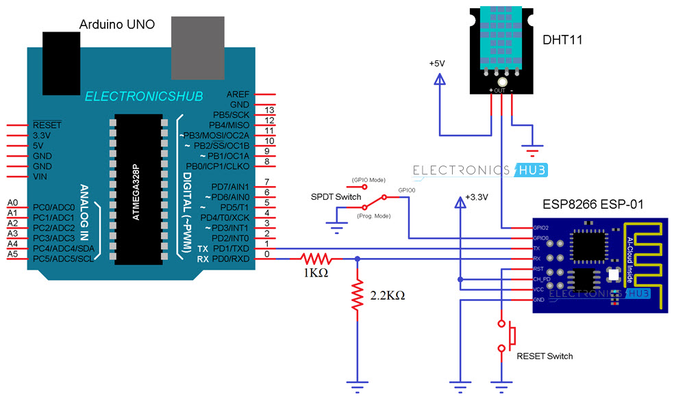
Components Required
- Arduino
- DHT11 Humidity Sensor
- ESP8266
- Jumper Wires
- Mini Breadboard
- Resistors (1 KΩ and 2.2 KΩ)
- Push Button
- Slide Switch
Code
The code for connecting DHT11 Humidity Sensor with ESP8266 and ThingSpeak API is given below. You have to change the code i.e. add your WiFi Network’s SSID and Password at appropriate places.
Also, you need to note down your Write API Key from ThingSpeak Channel and paste it in the code.
In the previous project “CONNECT ESP8266 TO THINGSPEAK”, I have shown you how to create a channel in ThingSpeak and add fields for that channel. So, if you are unfamiliar with that information, please refer to that project.
NOTE:
- You have to download two libraries called “DHT” and “Adafruit_Sensor”. You can download these libraries from these links: DHT and Adafruit_Sensor.
- Download them in zip format, extract the contents and copy the folders to Documents–>Arduino–>libraries
Working
Make all the connections as per the circuit diagram. Here, I’ll be uploading the code directly to the ESP8266 Module. This means that the existing code or firmware will be erased.
Before uploading the code, connect the GPIO0 to GND and RESET the ESP Module to enable Programming Mode.
Also, select “Generic ESP8266 Module” in the Boards section of the Arduino IDE. Make sure that you have selected the correct COM PORT.
After uploading the code, first, disconnect the GPIO0 from GND (you can let is float) and RESET the ESP Module.
Now, if you open the Serial Monitor and set the baud rate to 115200 and also select “Both NL & CR” option, you can see the progress of the ESP8266 Module.
First, it will get connected to the WiFi Network. Then, immediately, it will try to read the data from the DHT11 Humidity sensor and calculate the Temperature and Humidity values based on that data.
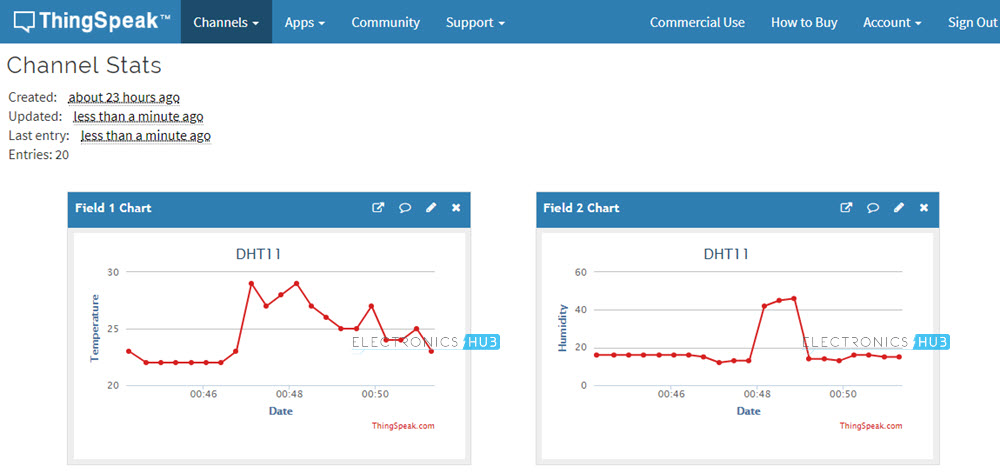
After this, the values of temperature and humidity will be uploaded to the ThingSpeak API. If you open your channel in the ThingSpeak, you can see the chart associated with the values from the DHT11 Sensor.
Conclusion and Applications
- In this simple project, I have shown you how to interface DHT11 Humidity Sensor with ESP8266 and ThingSpeak API.
- You can monitor the DHT11 Sensor Data from anywhere in the World just by sitting in front of a computer.
- This project could be your first implementation towards a bigger and better Weather Station with many other sensors.
The post DHT11 Humidity Sensor with ESP8266 and ThingSpeak appeared first on Electronics Hub.
Monday, 16 April 2018
When nuclei catch up with electrons
Two robots are better than one: 5G antenna measurement research
Some superconductors can also carry currents of 'spin'
Sunday, 15 April 2018
Thin, flexible polymers record 'conversations' deeper in the brain with less injury-risk
When superconductivity disappears in the core of a quantum tube
Saturday, 14 April 2018
Connect ESP8266 to ThingSpeak
When makers and hobbyists think of Internet of Things (IoT), two things come to their mind: one is ESP8266 and the other is ThingSpeak. One is the Hardware part of the IoT System whereas the other provides the necessary API (or the user interface) for the system. In this project, I’ll show you how to Connect ESP8266 to ThingSpeak Application and how the ESP8266 ThingSpeak collaboration works.
Overview
We have already seen one such IoT implementation using ESP8266 and aREST Platform. What makes ThingSpeak different and special is that is uses simple HTTP Protocol to transfer, store and retrieve information from different sensors.
Also, the ThingSpeak Application allows us to log the sensor data, track locations and even social networking of things.
Another important thing (or rather a unique feature) about ThingSpeak is its support from MATLAB. The close relationship between ThingSpeak and MATLAB has lead to integrate several key features of MATLAB into the ThingSpeak Application.
One such feature is to analyse and visualize the user data i.e. the sensor data in a graphical way without the MATLAB License.
Keeping the corporate stuff aside, the ThingSpeak Application is a great tool for our IoT related projects and hence this project focuses on the basics i.e. how to connect ESP8266 to ThingSpeak Application and also how the ESP8266 ThingSpeak Interface can be used in our future projects.
Creating ThingSpeak Account
The first thing you need to do is to create an account with ThingSpeak. Since the collaboration with MATLAB, you can use your MathWorks credentials to login to ThingSpeak using the Sign In link from this page: THINGSPEAK
If you do not have one, you need to create an account with MathWorks and login to ThingSpeak Application.
NOTE: The MathWorks Account can be used for both MATLAB as well as ThingSpeak logins.
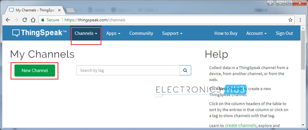
After logging in, you need to create a new channel for the data to be stored. For this go to Channels–>My Channels and click on New Channel.
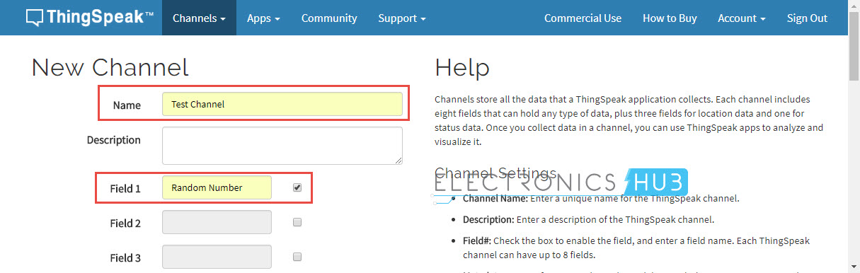
Enter the name of the channel and name of Field 1 in the corresponding sections. Fields in a channel are used to hold the data and each channel can have up to 8 fields. After entering the details save the channel.
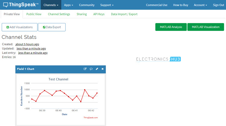
In my case, I’ve created a Channel called “Test Channel” and the Field 1 as “Random Number”. You will see why in the later sections.
There are a few other things you need to do in the ThingSpeak Application, but I’ll tell about it when you need it.
The next step is to prepare the hardware for the project, which includes ESP8266 WiFi Module, Arduino UNO Board and a few connecting wires.
Prerequisites for the Project
I’ll two ways of how to connect ESP8266 to ThingSpeak Application. For both the ways, you need to make sure that your ESP8266 Module is loaded or flashed with AT Commands Firmware.
For more information on this, I suggest you to go through the procedure mentioned in the project HOW TO UPDATE FLASH ESP8266 FIRMWARE.
NOTE:
- For flashing the AT Commands firmware, you need to enable the programming mode in ESP8266 by connecting GPIO0 to GND and resetting the module.
- But in this circuit (assuming you have already flashed the firmware), the ESP Module is in Normal Mode i.e. GPIO0 can be left floating.
After flashing your ESP with AT Commands Firmware, you can now proceed with connecting ESP8266 to ThingSpeak. As I said before, you can do this in two ways: One is through AT Commands and the other way is through Arduino (even this way uses AT Commands but Arduino controls them).
I’ll show you both ways to connect ESP8266 to ThingSpeak.
Circuit Diagram for ESP8266 ThingSpeak Interface through AT Commands
The circuit diagram in order to connect ESP8266 to ThingSpeak is very simple. In fact, you might have already seen this connection before. The Arduino UNO Board is used just to transmit the data between the computer and the ESP8266 i.e. it acts as an USB-to-UART Converter.
Components Required
- Any Arduino Board or USB-to-UART Converter
- ESP8266 WiFi Module (ESP-01)
- Connecting Wires
Connect ESP8266 to ThingSpeak using AT Commands
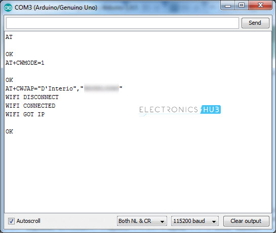
Connect the Arduino board to the computer and open the serial monitor of Arduino and check for connectivity using the following command.
Note that I have set the baud rate to 115200 and also selected “Both NL & CR” option in the Serial Monitor.
After you get a response as “OK”, you can proceed with connecting your ESP Module to your WiFi Network using the following command.
Replace SSID with the name of your WiFi Network and enter the password in place of PASSWORD.
You will now get a confirmation response regarding WiFi Connection as follows.
WIFI GOT IP
OK
Now, you need to set single connection using the following command.
Next step is to connect to the ThingSpeak API using TCP Protocol. For this, you need to use the following command.
Alternatively, you can use the IP Address of the host api.thingspeak.com i.e. 184.106.153.149.
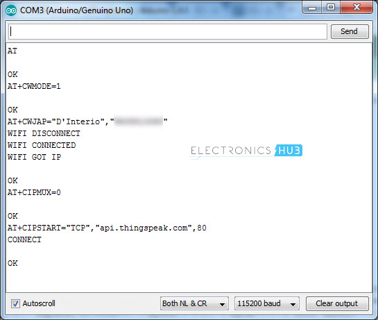
NOTE:
- After starting the TCP connection, if you don’t perform any action, the connection will be closed automatically after some time, usually after 1 minute.
Now, you have successfully enabled the “TCP” connection between the ESP8266 and ThingSpeak. Next, you can send any data through this TCP Connection.
For this, use the following commands one after the other.
GET /update?api_key=XXXXXXXXXXXXXXXX&field1=255
AT+CIPCLOSE
Once the TCP connection is established, you can send data using certain commands. This part can be a little tricky but trying it for a couple of times, you will understand the process.
In order to send the data, you need send three different information: One is the actual send command, next is the data along with the ThingSpeak Field Key and finally the close connection command. I’ll try to explain these steps in a detailed way as possible.
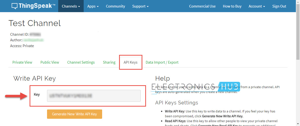
Before sending the data, you need to acquire the API Key. For this, go to you channel (the one you have just created) and click on “API Keys” Tab. Below that, you can find Write API Key, which is an alphanumeric string of 16 characters. Make a note of this key.
Now, use the following command to initialize the data transmission.
The value 51 is the length of the data to be transmitted. This includes the complete data including the API Key and the “\r” and “\n” values. For this command, you will get the following response.
>
Now type the following information and hit send. Here, “XXXXXXXXXXXXXXXX” is nothing but the 16 character Write API Key, which you have just copied. And the number “143” is the actual data you are transmitting to field1.
After typing this text and hitting on send, you will not get any response. It is actually waiting for the close command. Once you hit send for the above text, immediately type the following command and hit send.
The moment you hit send, you will get the following response (not the exact one, but something similar).
SEND OK
+IPD,1:5CLOSED
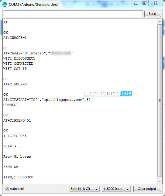
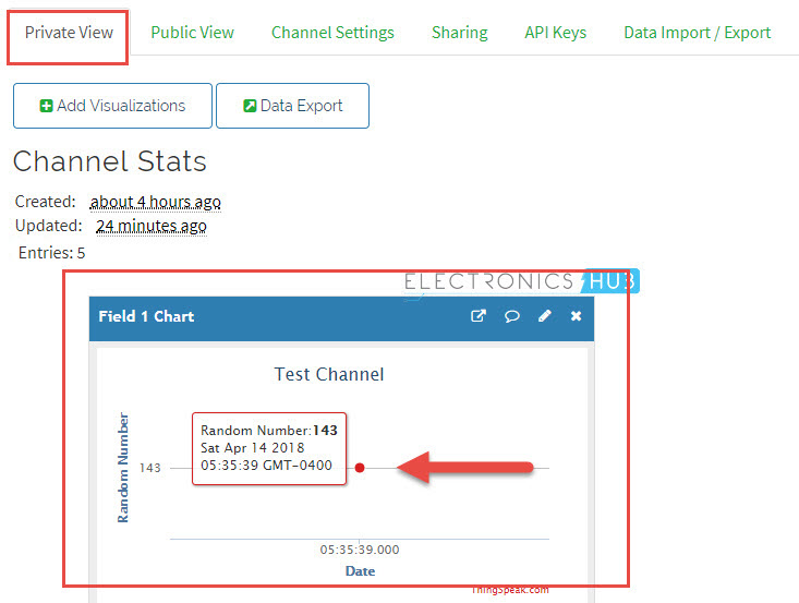
Here, the number 5 means, it is my 5TH message to that Key. Now, Open the ThingSpeak API and open your channel. In the “Private View” tab, you can see the value ‘143’ in the Field 1 Chart.
That’s it. If you understood and followed all these steps, then you might have successfully connected ESP8266 to ThingSpeak API. To send more data, repeat the steps from creating the TCP Connection.
Circuit Diagram for ESP8266 ThingSpeak Interface using Arduino
Since I’ll be programming the Arduino and controlling the ESP8266 through Arduino, the circuit diagram will be slightly different. But the components will be the same.
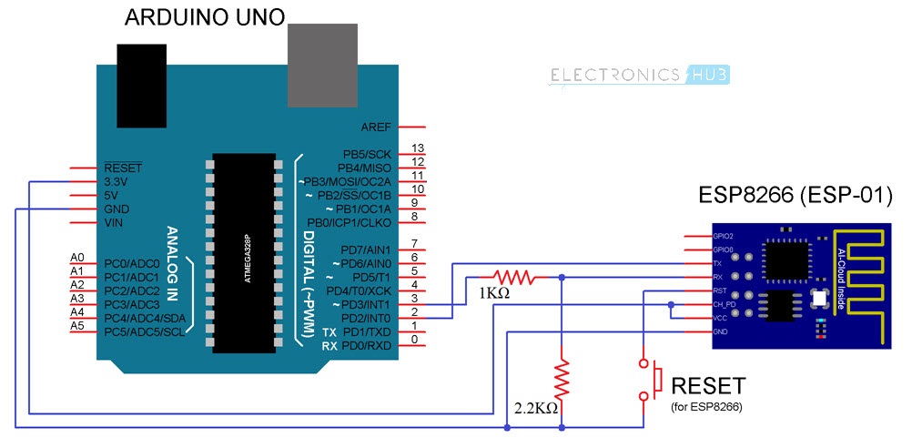
Connect ESP8266 to ThingSpeak using Arduino
I don’t want to ask the same old question i.e. are you tired of typing all the AT Commands manually? Obviously, the answer will be yes. Here comes Arduino to the rescue. Make all the connections as per the above circuit diagram and we will proceed with the code.
Code
Use the following code to upload to Arduino. Note that you have make few changes to the code. The changes will be regarding WiFi SSID, WiFi Password and API Key (16 character). I think, rest of the values can be left as it is.
After uploading the code, if you open the serial monitor (baud rate set to 9600), you can see the AT Commands being transmitted to the ESP8266 Module.
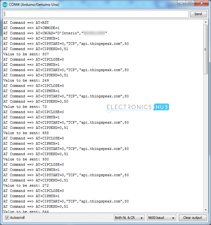
Initially, the AT Commands will setup the WiFi Connection to the ESP Module. After enabling the connection, the Arduino will establish TCP connection to the ThingSpeak API and transmits the random number for every 5 seconds.
This data can be monitored in the ThingSpeak API Website i.e. in the channel you created (under the Private View tab).
Conclusion & Applications
- In this project, I have shown you hoe to connect ESP8266 to ThingSpeak API using both the direct AT Commands as well as through Arduino.
- Using the ThingSpeak API, you can monitor sensor data from anywhere in the World.
- Most frequently used sensors are DHT11 Humidity and Temperature Sensor, DS18B20 Temperature Sensor and LM35.
The post Connect ESP8266 to ThingSpeak appeared first on Electronics Hub.
Friday, 13 April 2018
Smallest volume, most efficient wireless nerve stimulator
Mini toolkit for measurements: New chip hints at quantum sensors of the future
Diamond-based circuits can take the heat for advanced applications
Build a color-changing mini-lamp
 If you want to build advanced things like internet-connected gadgets and more, you need to use a microcontroller.
The easiest way to get started with microcontrollers is using the Arduino.
When I was living in Berlin I did a lot of Arduino workshops.
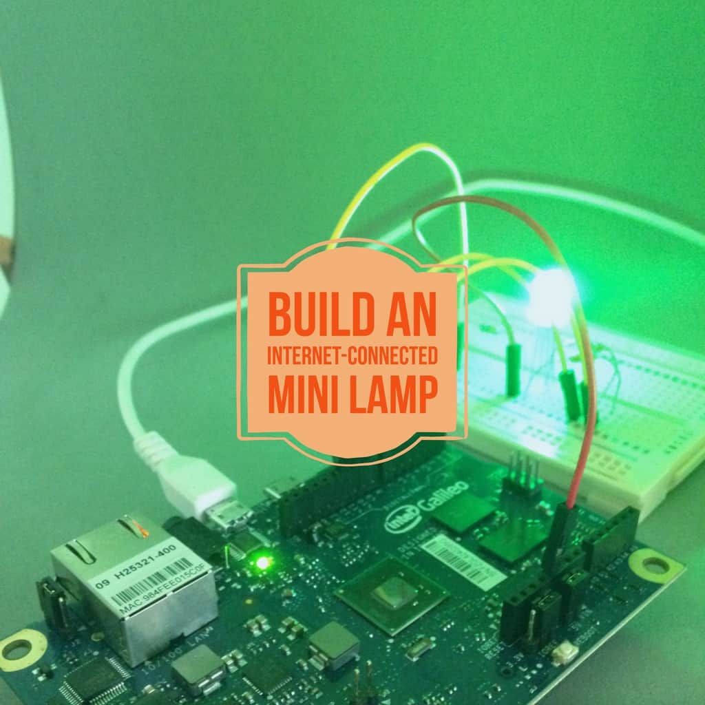
One of the most fun projects I did with my students was the Weather-Predicting Mini-Lamp that would change color depending on what temperature it was going to be the next three hours.
It did this by connecting to the Internet, finding weather data from a weather-site, extracting the temperature for the next 3 hours, then translating this to a specific color using an RGB LED.
The Weather-Predicting Mini-Lamp project is a part of the new Getting Started With Electronics course bundle that I just released:
https://learn.ohmify.com/p/getting-started-with-arduino-bundle/?product_id=612624&coupon_code=TWENTYFIVEOFF
Get 25% off with the code TWENTYFIVEOFF (valid until the end of April).
Have an electronics-filled weekend ahead!
Keep On Soldering!
Oyvind @ build-electronic-circuits.com
Copyright Build Electronic Circuits
Thursday, 12 April 2018
Wiggling atoms switch the electric polarization of crystals
Recycling experts hit milestone in quest for zero-waste phone
What Is Swarm Intelligence? And How It Predicted Time’s Person Of The Year Correctly
What Is Swarm Intelligence? Swarm Intelligence dictates that groups are smarter in thinking as compared to individuals. It exists when many individuals coordinate with one another in decentralized systems of control based on the principle of self-organization. We often see this manifest in nature such as flocks of birds, a swarm of bees, and school of fishes. Swarm intelligence combines the powers of many into one. Swarm intelligence is beautiful because it allows the exploration of a variety of alternatives based on a principle of collective wisdom that is often generated based on the environmental surroundings and individual interactions among the members. Thanks to the advent of AI, we can now implement swarm intelligence to humans. People can collectively work together to make predictions, pick stocks, reach decisions, ask questions and more by applying artificial swarm intelligence. Swarm intelligence is often studied in two major areas: Natural Systems: Natural systems comprise of the swarms that manifest in biological systems such as the colonies of termites and ants, a herd of land animals and more. Artificial Systems: Artificial Systems comprise of systems generated by humans such as robotics and more. Swarm intelligence is based on the following characteristics: The system is composed of a large number of individuals The system is composed of homogenous individuals having similar characteristics. Information must be exchanged among the individuals either directly or via the environment. In other words, the group must operate on the basis of self-organization. Interactions among the individuals must only be based on local information. Research in the field of Swarm intelligence started back in the 1980s. Since then it has found its application in many practical fields such as optimization problems, social sciences and engineering. Swarm Intelligence makes a system flexible since swarms modify their behaviour according to their surroundings. Therefore they can adapt to varying landscapes and problems. Moreover, since the system is not dependent on a particular individual in the group, it is robust and continues to perform even if some members of the group become inactive and unable to perform. Swarm intelligence also makes a system scalable, it can work in small groups to large groups compromising of millions of individuals without affecting the quality of the system or requiring any changes. The system works fast, changes can be incorporated into the system quickly. Swarm intelligence also makes it possible to perform parallel actions in the system because individuals in the system can work by performing different actions simultaneously at different places. This makes the system much more useful as it makes it more flexible and it allows the swarm to work on different complex aspects of the task simultaneously. On the downside, it is difficult to predict the behaviour in a system based on swarm intelligence. Even if one understands the behaviour of an agent working in the system, it will be difficult to predict the behaviour of the whole swarm or colony. The system is highly sensitive to changes. Even a small change in the environment of the swarm or colony may result in the change in the system. Humans did not develop swarm intelligence naturally because unlike other creatures they do not have the subtle connections amongst each other to form a tight feedback loop. For instance, birds detect movement in the flock. Fish detect the tremors in the water. For humans, until a few years ago no such connection was possible. However, now due to the revolution in information technology, such connections have become possible. Today we can use the internet and other technology to connect with almost anyone located anywhere in the world....
read more
The post What Is Swarm Intelligence? And How It Predicted Time’s Person Of The Year Correctly appeared first on Electronic Circuits and Diagrams-Electronic Projects and Design.
Wednesday, 11 April 2018
What’s the fastest way to build prototypes?
 Yesterday I met Martin.
He is a consultant that finds and fixes problems with pipes.
So he has these devices that he places into tubes that will scan the pipes or give images from inside the pipes.
Using these devices, he can find the problems and come up with solutions on how to fix the pipes.
Anyway, yesterday he told me that this is a small industry. So the devices he needs for inspecting the pipes can easily cost $50.000 USD!
But Martin is a handy guy.
And he found out that some of these costly devices are pretty simple: A motor, a sensor, some mechanics and a way to control the motor and read the sensor.
He knew how to assemble mechanical parts, but he did not have any background in electronics.
So he didn’t know how to control the motor and read the sensor…
That was until he discovered the Arduino.
He took a course to learn the basics, and that was all he needed to understand how to control the motor and the sensor.
Suddenly, he could build a prototype of the device himself.
It’s not as good as the $50k version, but it works ok and he will improve on it with time as he learns more about basic electronics and circuit board design.
The Arduino is a microcontroller board – made for people with non-technical backgrounds like designers, entrepreneurs or even kids.
It’s really easy to program and you can make a lot of things with it – even your own cell phone!
Last week I released course bundle for helping you get started with Arduino.
It’s on sale for 25% off by using the code TWENTYFIVEOFF.
Learn more here:
Keep On Soldering!
Oyvind @ build-electronic-circuits.com
Copyright Build Electronic Circuits
Tuesday, 10 April 2018
New sodium-ion electrolyte may find use in solid-state batteries
RFID (Radio Frequency Identification) – A Brief Guide
Among the most irritating experiences in shopping, standing long queues to get the items you have purchased run through a scanner into the system is on top of the list. However, this can be cut short by the application of RFID technology in the sector. What is RFID? RFID (radio frequency identification) refers to the technology in which data is encoded in unique tags and tracked by electromagnetic fields that interrogate radio waves from the labels and feed them into the system. Similar to UPC (universal product code), RFID can be used to track sales at a faster rate and within larger radii. With the application of this technology, shopping will be as easy as filling your basket with items and walking out of the mall. Electronic, magnetic fields will interrogate the codes on your products and fed into the system. After the system determines the amount that you should pay for the goods, the bill is then transmitted to your electronic bank and the amount charged. This technology will not only allow shopping centres to serve more people as queues will be a thing of the past. Additionally, companies will have an easier time tracking their products thus ensuring that no product goes out of stock. Working of RFID For an RFID system to operate, two major components are required; the key and the reader. The key is a label that is embedded with a transmitter and a receiver used to relay various information. The tag consists of a microchip and an antenna used for transmitting signals that contain serial numbers for particular products. When passed via an RFID reader, the system emits a signal that activates the tags in the products that in turn send encoded information which in most cases is a serial number to the system. The information is transmitted to a network through a communications interface. The host computer system uses this information to determine the amount of products purchased and their worth before transferring them to a billing system. However, two types of tags can be used in the procedure: an active tag that is fitted with a battery activated in the presence of an RFID reader and thus relaying information independently. A passive tag, on the other hand, has no power source of its own and therefore depends on the power of the frequency transmitted to relay encoded information to the reader. To avoid collision of data from different tags, collision detection is applied in the RFID system. This enables the system to read each code amidst similar tags thus allowing the order to determine the number of similar products. History of RFID RFID technology was first applied by Leon Theremin in 1945 when he designed a listening device for the Soviet Union. In Leon’s model, radio waves were transmitted with additional audio information. The sound waves vibrated the diaphragm of the model thus altering the resonator’s shape, therefore, modulating the reflected radio frequency. Later in 1948, Harry stockman conducted more research on the field and concluded that extra research needed to be carried to solve power problems that were reflected in the model. Twenty-five years later, the predecessor of modern RFID was brought into life by Mario Cardullo. Mario’s model consisted of a passive radio transponder with memory. This operated under sound and light media transmission. The technology was seen to apply to some fields that included the banking and the medical sectors. Later in 1973, the technology got a significant advancement after Stephen Depp, Robert Frayman and Alfred Koelle created a 915 MHz portable system that applied the use of 12-bit...
read more
The post RFID (Radio Frequency Identification) – A Brief Guide appeared first on Electronic Circuits and Diagrams-Electronic Projects and Design.
Monday, 9 April 2018
Arduino course
It was about ten years ago that I first heard about it.
..”the Arduino”.
In the beginning, I wasn’t sure what to make of it.
It was so easy to use.
Is it just a toy?
Since then, I’ve come to love the Arduino.
Arduino is a board with a microcontroller that you can easily program to do awesome stuff.
But I don’t just teach how to use it.
I also use it in my professional life – because it’s really awesome for making prototypes fast.
Or to test out ideas.
In the past, I have done many workshops and courses on the Arduino.
So I decided today to release a four-course bundle to learn Arduino.
Get 25% off full price by using the code TWENTYFIVEOFF (valid until the end of April):
Keep On Soldering!
Oyvind @ build-electronic-circuits.com
PS! Not sure what Arduino really is? Check out this article:
https://www.build-electronic-circuits.com/what-is-arduino/
Copyright Build Electronic Circuits
Ultra-powerful batteries made safer, more efficient
Saturday, 7 April 2018
How Self Driving Cars Work
Annually, over one million people lose their lives to road carnages. Although the government tries to curb the situation, the number of car accident related deaths are reduced only by a small margin. Due to this, methods to handle road accidents and traffic jams have been a trending discussion for quite a long duration of time. Among the ideas presented to curb this, traffic lights and other inventions have been introduced in the transport sector. However, the idea that seems to be most efficient is the automation of vehicles. Since a few years, technology has been applied to cars to aid them in different tasks. Among these tasks are; car parking, acceleration and even observing distance between cars. Most recently, talks about autonomous vehicles (also called self-driving vehicles and driverless vehicles) got into the market and seem to be welcomed by many. What is a driverless vehicle? A driverless vehicle is one that can operate to predetermined destinations free of a human driver. This is possible as the car is fitted with coordinate sensors and software that controls its navigation. With this in place, vehicles may be able to operate under no or minimal human involvement similar to autopilot in aeroplanes. With the introduction of this technology, traffic jams are expected to be reduced significantly and fewer car accidents will be seen. However, with immature levels of technology in early years, the idea proved to be an expensive endeavour, and thus little progress was evidenced. As years passed by, several car manufacturers showed interest in this idea leading to some manufacturers even producing precursors. Although the concept is still under construction, it is evident that it will revolutionize the transportation sector majorly. How do self-driving cars work? To efficiently navigate, a self-driving car needs to be well conversant with what’s happening in its surroundings and the geological appearance of the general area. This enables the car to make optimum decisions on deciding which route is best to take and also to avoid it from running into obstacles. To achieve this, driverless vehicles are integrated with GPS mapping, sensor lasers, a windscreen camera and advanced control systems for interpretation of information from the sensors. The data so obtained is incorporated into the car’s map through a simultaneous localization and mapping algorithm thus creating a clear picture of its surroundings. The windscreen camera and the bumper mounted radar keep track of pedestrians, motorists, street lights, road signs, traffic lights and other vehicles around the car. These are also fed into the vehicle’s mapping system ensuring that the car follows traffic rules and allows pedestrians to cross. For more accurate results a driverless car is fitted with gyroscopes, altimeters and a tachometer. Additionally, it is equipped with an odometer and computer vision that helps to decode the information in a manner that the vehicles inbuilt software can interpret. For better projection of what are in its surroundings, the car uses newer range Lidar (light detection and range) sensors as they provide a more precise image compared to GPS. To ensure that the vehicle is operated similarly to that by a professional driver, the software is programmed with neural networks that represent real driving experiences. This allows the car to take the best course of action in different situations. These neurons also enable the vehicle to decipher approaching bodies thus ensuring it responds accordingly to avoid incidents. Classification of self-driving vehicles With driverless vehicles being designed, there are different levels of automation as classified by SAE international. This ranges from a “hands-on” driving experience to a “driver-free” mode of driving. In each of these levels,...
read more
The post How Self Driving Cars Work appeared first on Electronic Circuits and Diagrams-Electronic Projects and Design.
Control a Relay From Anywhere in the World using ESP8266
Let us continue exploring the ESP8266 Module by making a project to Control a Relay from anywhere in the World using ESP8266. All you need is an account in the aREST application and a web browser with internet connectivity (after setting up the hardware i.e. Arduino, ESP8266 and Relay Module).
Overview
In the previous ESP8266 project called CONTROL A RELAY USING ESP8266 AND ANDROID, I have shown you how to control a relay module (subsequently, the load connected to the relay) through WiFi with the help of ESP8266 and an Android App developed using MIT App Inventor 2 Application.
Even though it is a wonderful project, where you develop your own Android App and control the Relay Module using that App, the main limitation of that project is its scope of connectivity.
To be clearer, the Android Phone (on which the App is installed) and the ESP8266 Module (to which the Relay is connected to) must be connected to the same WiFi Network. If you try to control it outside the WiFi Network of the ESP Module, then you’ll end up being disappointed.
So, in this project, we will take the previous project a step further by seeing how to control a relay from anywhere in the World. Yes. That’s right. You can Control a Relay from anywhere in the World with just a Web Browser.
In order to achieve this, I’ll be using a unique platform called aREST. Using aREST with ESP8266, you can easily implement a true IoT Home Automation Project.
A Brief Note on aREST
The main aim behind the development of the aREST platform is to take the concepts of IoT and Home Automation closer to the DIY Community.
Using the aREST Platform, you can create web-based applications and control different types of boards like Arduino, ESP8266 and Raspberry Pi from anywhere in the World.
In order to use the aREST Platform, all you need is an account in the aREST (not mandatory, I’ll explain in the Working), and a few libraries for the ESP8266 (or Arduino). That’s it.
More information on aREST and how to use it with ESP8266 will be explained in the later sections.
Circuit Diagram
In order to control a relay from anywhere in the World, you need to make the connections as per the following circuit diagram. Arduino is not mandatory as it is used just to program the ESP8266 Module i.e. it is acting as an USB-to-Serial Converter.
If you happen to have a dedicated USB-to-Serial Converter, then you will not need the Arduino Board.
Components Required
- USB-to-Serial Converter (Arduino Board)
- ESP-01 (ESP8266 Module)
- Two Channel Relay Module (only one channel is used)
- Button
- Resistors (1 KΩ and 2.2 KΩ)
- Jumper Wires
- Slide Switch (SPDT)
Circuit Design
The design of the circuit for controlling a relay from anywhere in the World is very simple. In fact, the design is similar to what we made in the ANDROID APP CONTROLLED RELAY PROJECT.
So, I wouldn’t go into the details of the circuit once again and I suggest you to refer to that project for detailed circuit design.
Code
The code for the project is given below. This code is inspired from the aREST example “ESP8266_cloud”. I’ll explain more about in the Working section.
Hardware and Software Configuration
Let us now try to understand the project and see how to control a relay from anywhere in the World using ESP8266.
First, make all the necessary connections as per the circuit diagram. Connect the Arduino to the computer and connect the GPIO0 to GND and reset the ESP Module. Before uploading the code given above, you need to make a few additions and changes.
The first important thing is you need to special libraries called “aREST” and “PubSubClient”. Both these libraries can be downloaded from the following links aREST and PubSubClient.
Download the zip files and extract the contents. Then copy both the folders called “aREST-master” and “pubsubclient-master” to Documents–>Arduino–>libraries. The path will be something like this “C:\Users\Ravi\Documents\Arduino\libraries”.
After doing this, copy the above code into the Arduino IDE and move to the line that says “char* device_id = “re1403”;”. This line contains the unique Device ID specific to your device. Replace this with your ID with a maximum of 6 characters (can be alphanumeric, not sure about special characters).
NOTE: Do not forget to replace “re1403” with your own Device ID.
Once you have assigned the Device ID, move on to the next line and enter your WiFi Network details i.e. SSID and Password. Then move to line that says “arestVar.set_name(“MyESP”);”. Here, you can set a name to your device. This name will be visible once you connect to the aREST Dashboard.
Now you can upload the code to the ESP Module. After uploading, if you open the serial monitor, you can see the status whether the ESP Module is connected to the aREST framework or not.
Control a Relay from anywhere in the World using ESP8266 and a Web Browser
Let us now see the implementation of the project. Remember that, in the circuit, I have connected the Relay Module to the GPIO2 of the ESP Module.
After uploading the code and getting connected to the aREST Server, open a web browser connected to a different network than the ESP8266 Module and enter the following URL.
Using this URL, you are configuring the device with id “re1403” and setting its pin 2 as output. If the configuration is successful, you will get a response as following.
Now, that your device is configured, you can go ahead and control its pins i.e. you can make the pin HIGH or LOW. For that, you need to use two URLs.
To make the pin HIGH, use the following URL.
The response to making the Pin HIGH is as follows.
And to make the pin LOW, the URL is:
The response to this URL is:
{“message”:”Pin D2 set to 0″,”id”:”re1403″,”name”:”MyESP”,”hardware”:”esp8266″,”connected”:true}
NOTE: The relay module, which I have used in the project is an active LOW one. So, a LOW on the ESP will turn ON the relay and a HIGH on the ESP will turn the relay OFF.
That’s it. You can follow all the above mentioned steps and control a relay from anywhere in the World using ESP8266 and aREST.
Control a Relay from anywhere in the world using ESP8266 and aREST Dashboard
Note that you do not need an account in the aREST Framework in order to implement the above mentioned process. But there is an advantage of creating an account with aREST.
Use the following URL and create an account in the aREST.
If you already have an account with aREST, login with your credentials using the above mentioned URL. After this, you will get the following page.
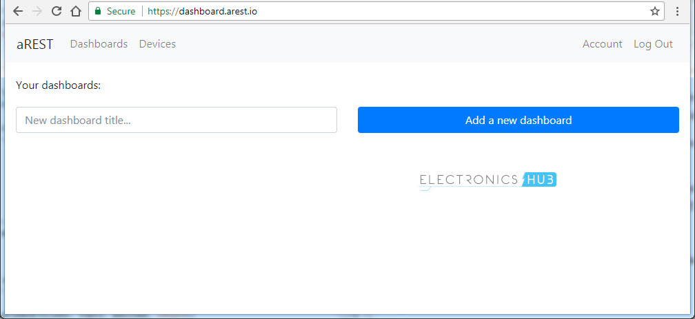
After this, enter a new dashboard title like “ESP8266_Relay” and click on “Add a new dashboard”. This will be added under “Your Dashboards:”. Open the newly created dashboard.
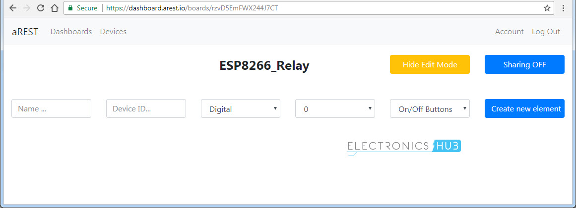
Here, you can add the device you want to control. Give a name to the Device, the Device ID (which you have mentioned in the program), type of Pin (Digital in our case), Pin number (Pin 2) and the type of control (ON – OFF Buttons) and create a new element.
NOTE: You can show or hide the edit details anytime.
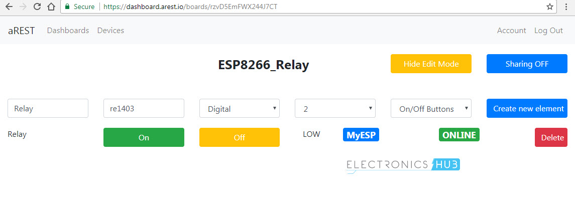
If everything goes well, the moment you click on create a new element (with all the details), you will get the name of device, which you set in the code (in my case, it is MyESP) and the status of it (ONLINE).
Now you can control the relay, which is connected to the GPIO2 of the ESP8266 through this interface. So, the benefit of creating an aREST account is that you need not enter the before mentioned URLs to control the ESP Module.
Control a Relay from anywhere in the World using ESP8266 and Android App
In addition to the URL and aREST Dashboard control of the ESP Module, I’ll show you how to create an Android App using MIT App Inventor 2 Application and Control a Relay from anywhere in the World using that app.
All you need is to create two Button elements in the App and a Web element as shown in the image below. I’ve added a few extra labels to mention the title of the project and also indicate the status of the relay.
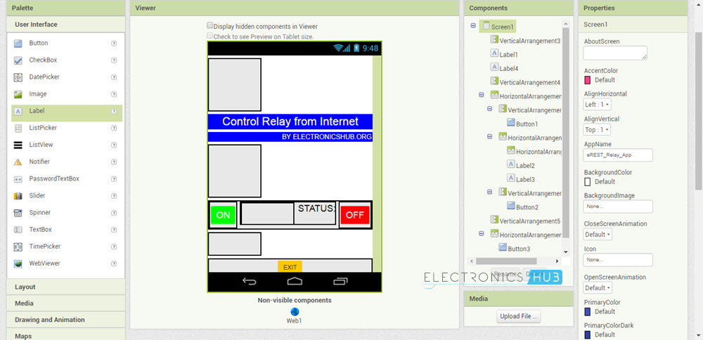
In the blocks section, create blocks for the Buttons and add the Web elements. Link those corresponding web elements to the URLs that I have mentioned earlier. So, when ever you click on the button, the app sends a request to that URL and as a result, controls the relay.
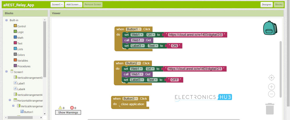
NOTE: I haven’t given the complete details of creating an Android App using the MIT App Inventor 2 Application. If you are interested, I can make a dedicated project on that topic as well.
Applications
- I think the applications of controlling a Relay and as a result an electrical appliance from the internet are very clear.
- A true IOT based Home Automation is one of the main and important application where you can monitor your home essentials like temperature, smoke alarm, etc. and at the same time control any electrical appliances, everything over the internet and from anywhere in the World.
The post Control a Relay From Anywhere in the World using ESP8266 appeared first on Electronics Hub.
-
CMOS (Complementary Metal Oxide Semiconductor) The main advantage of CMOS over NMOS and BIPOLAR technology is the much smaller power dis...
-
Bluetooth Controlled Electronic Home Appliances is a simple project, where we can control different electrical appliances and electronic de...
-
I was first introduced to logic gates when I was around 14 years old. I had heard that computers consisted of ones and zeroes. But I didn’t...


