Tuesday 31 May 2022

555 Police Siren Circuit with Build Instructions

In this tutorial, you’ll learn how to build a 555 police siren circuit using two 555 timer ICs.

The 555 timer is a popular integrated circuit (IC) for hobbyists and can be used for a great variety of projects. For this project, we are going to use it to create sound with a twist!

Instead of a “straight” sound, we are going to make the frequency change automatically so it ends up sounding like a wailing police siren.

The 555 Police Siren Circuit

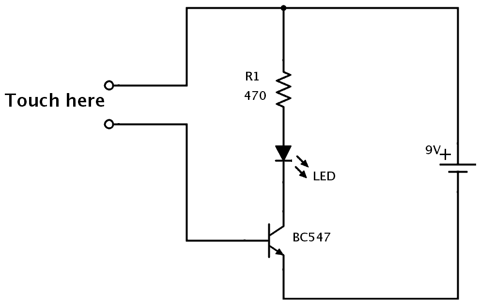
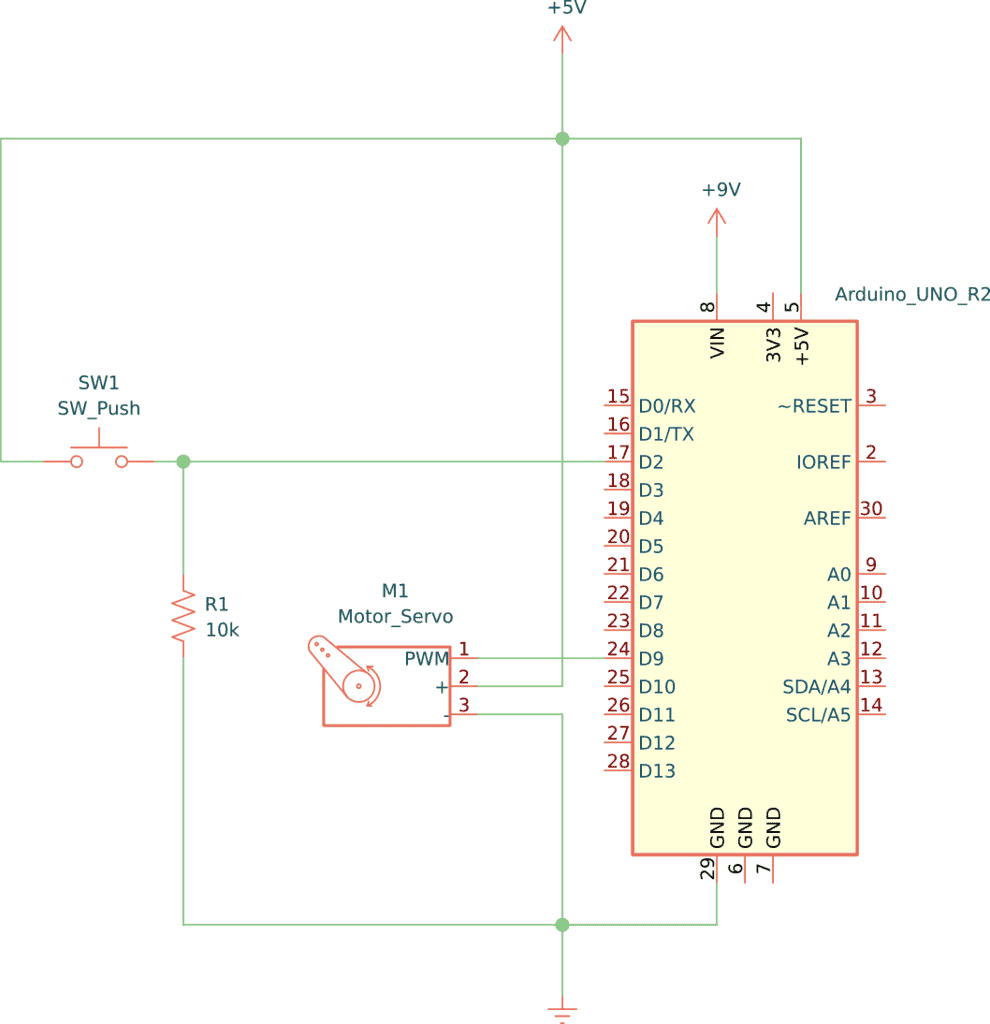
Below you’ll find the schematic for this circuit.

At first sight, the circuit might seem big and complicated. But if you take a closer look, you can see that the circuit is formed by three different basic circuits that we’ll go over in this article.

Schematics for 555 Police Siren

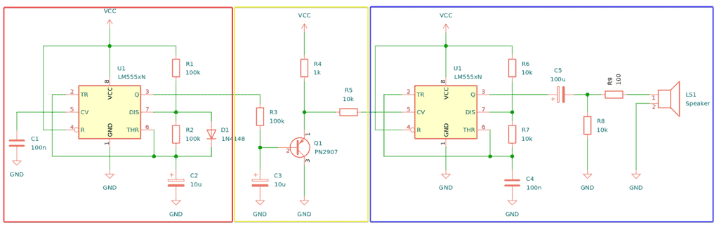
This project consists of the following three circuits combined:

  • Red square: Slow 555 circuit in astable mode
  • Yellow square: PNP switching circuit with a turn-on delay
  • Blue square: Fast 555 circuit in astable mode with a speaker and using CV to modify the frequency

Components Needed

  • 555 Timer IC x2
  • PNP Transistor (PN2907)
  • Small Signal Diode (1N4148)
  • 8 Ω Loudspeaker
  • 100k Ohm Resistor x3
  • 10 kΩ Resistor x4
  • 1 kΩ Resistor
  • 100 Ω Resistor
  • 100 µF Electrolytic Capacitor
  • 10 µF Electrolytic Capacitor
  • 100 nF Non-Polarized Capacitor

These are standard components you can find at most electronics shops.

How it Works

As you can see in the schematic, the circuit has three different parts for it to work. First, we have the astable multivibrator, which outputs an oscillating signal similar to this:

Output signal from 555 timer

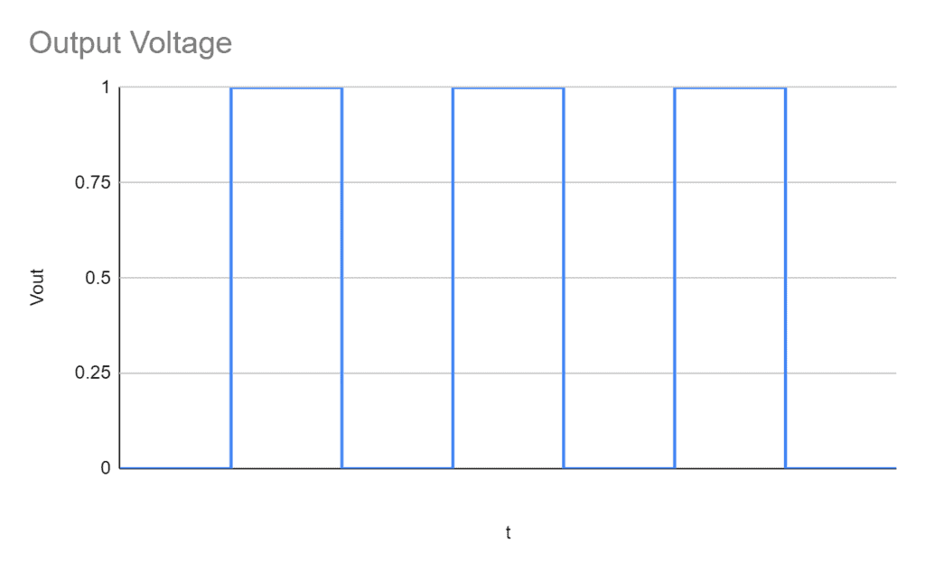
This is a very common configuration for 555 timers, and in this case, it’s configured to oscillate somewhat slow.

The second circuit is a PNP transistor switching circuit with a capacitor connected to its base. The capacitor will make a softer transition between 1 (max voltage) and 0 (GND). The output of this circuit will be a voltage going up and down and is connected to the CV pin of the third circuit.

The third circuit is almost the same as the first circuit, except for a couple of changes. First, it uses a much smaller capacitor, which will make the circuit reach higher frequencies. And second, it takes a varying voltage input on the CV (control voltage) pin. The output frequency will vary a bit up and down as this voltage goes up and down.

The result of this is a frequency that is going up and down, just like a police siren.

Building the Circuit

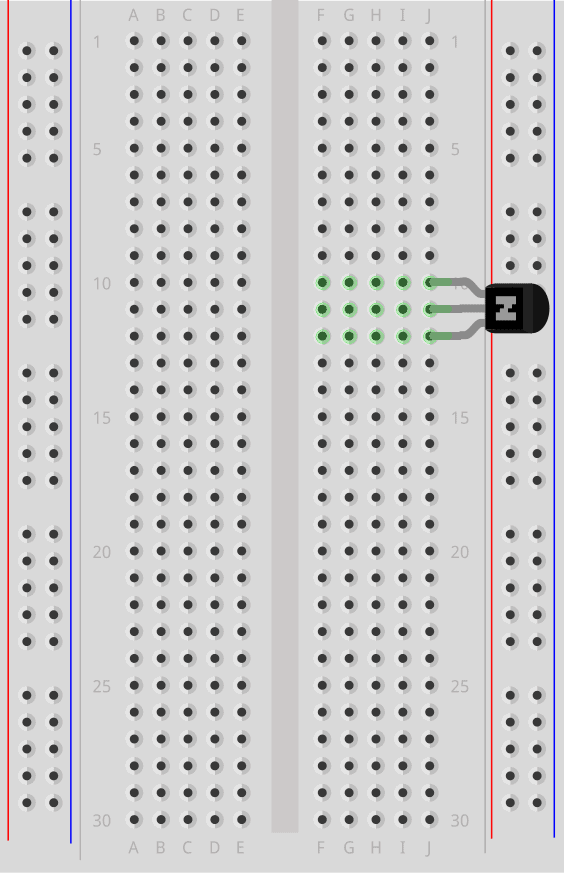
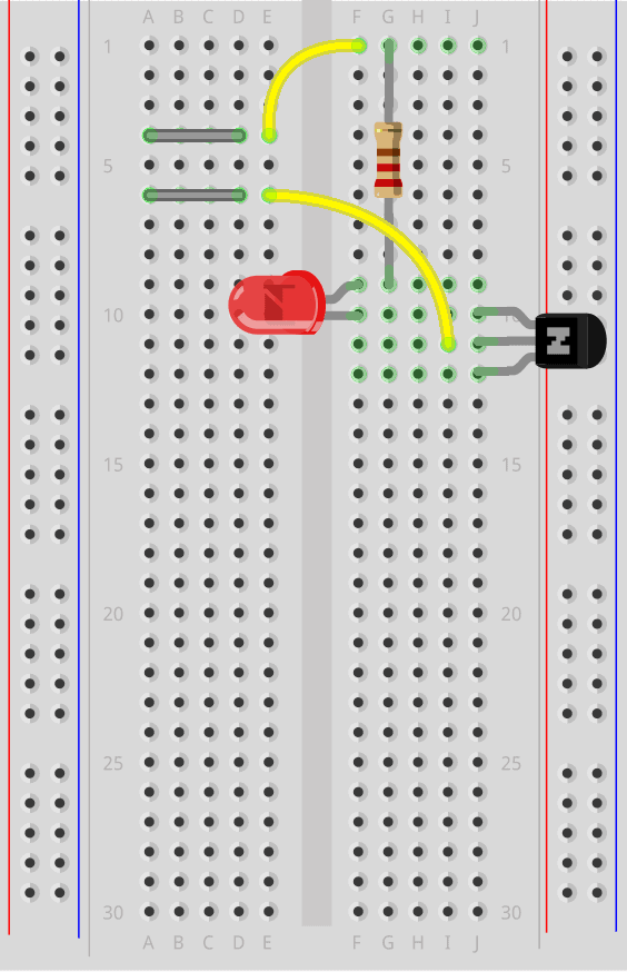
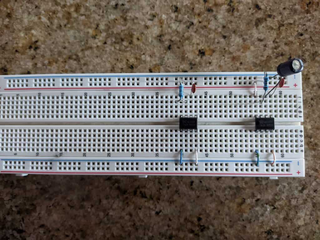
To build the 555 police siren circuit we are going to use a breadboard. First, connect every direct connection between the ICs, VCC, and GND.

Building the 555 Police Siren circuit on breadboard - step 1

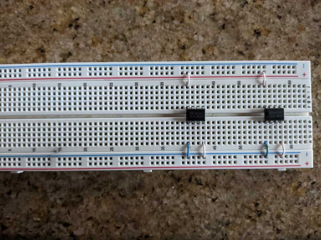
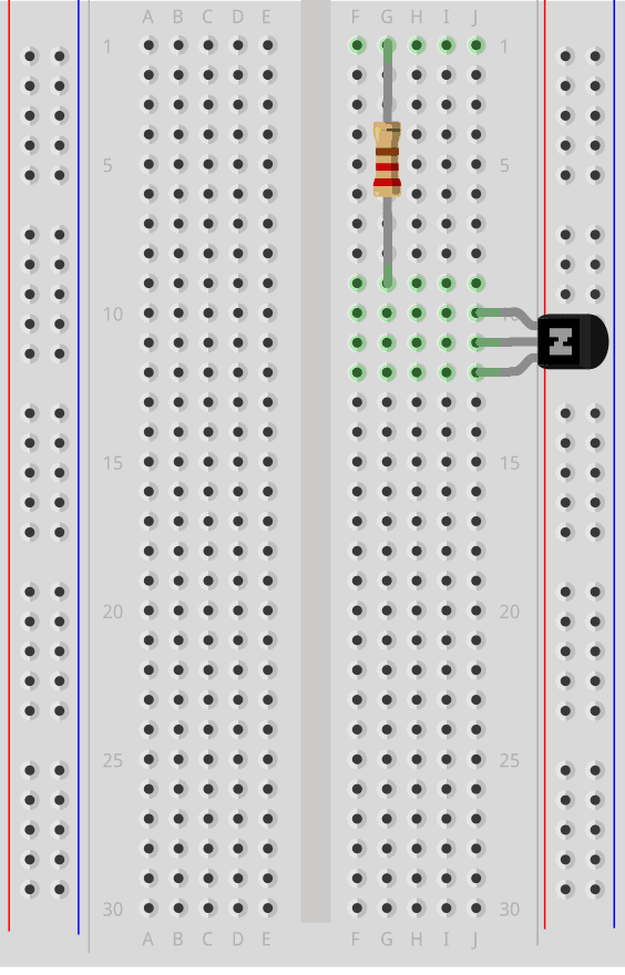
Then add the components that are connected between the IC, VCC, and GND. Remember to not cover all the holes in the row so you can add more connections later if necessary.

Building the 555 Police Siren circuit on breadboard - step 2

Then add the rest of the components and wires that make up the IC circuits. You can see that I used a small jumper (the yellow with blue cable) to take pin 6 to another row so that the components are placed more comfortably.

Building the 555 Police Siren circuit on breadboard - step 3

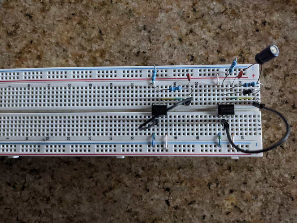
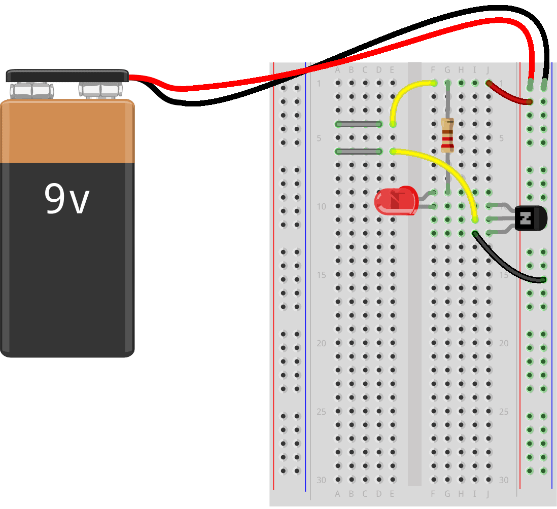
After this, connect the components for the switching circuit.

Building the 555 Police Siren circuit on breadboard - step 4

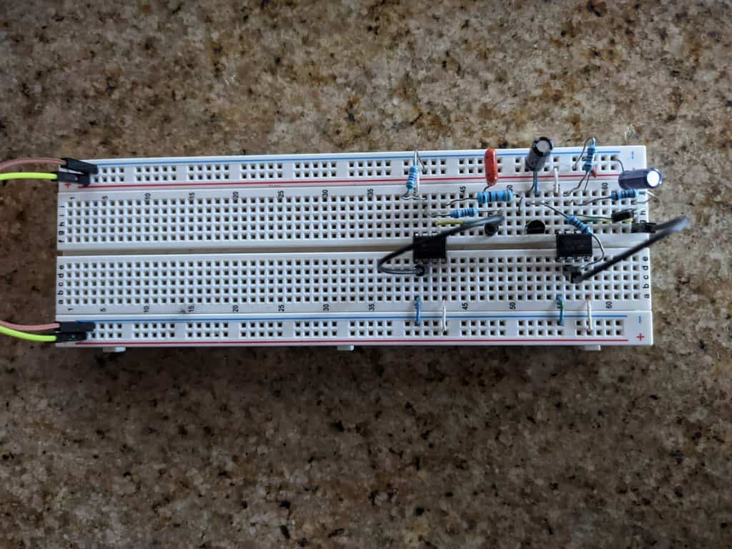
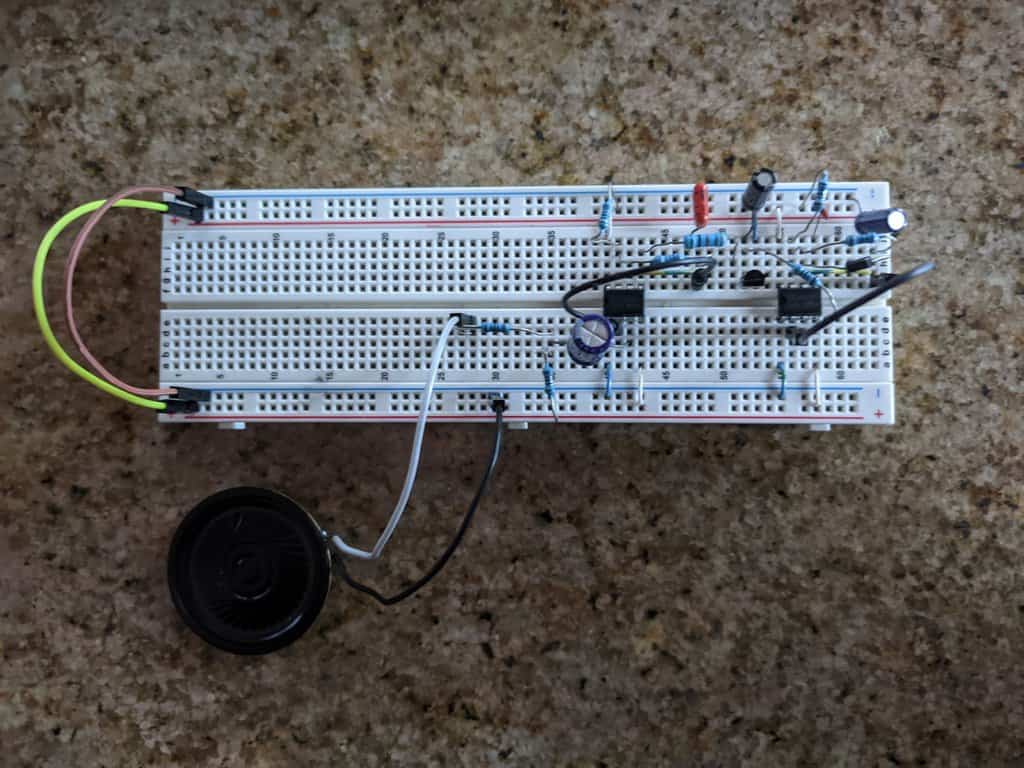
And then, add the speaker.

The finished 555 Police Siren circuit

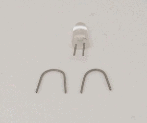
Remember that for every connection you can use any kind of jumper wire. I used small copper wires on occasions to avoid cluttering my circuit with a lot of oversized cables.

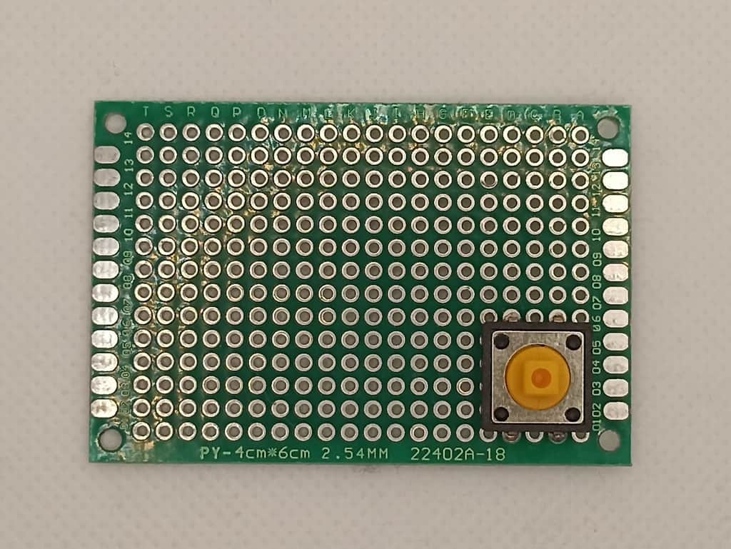
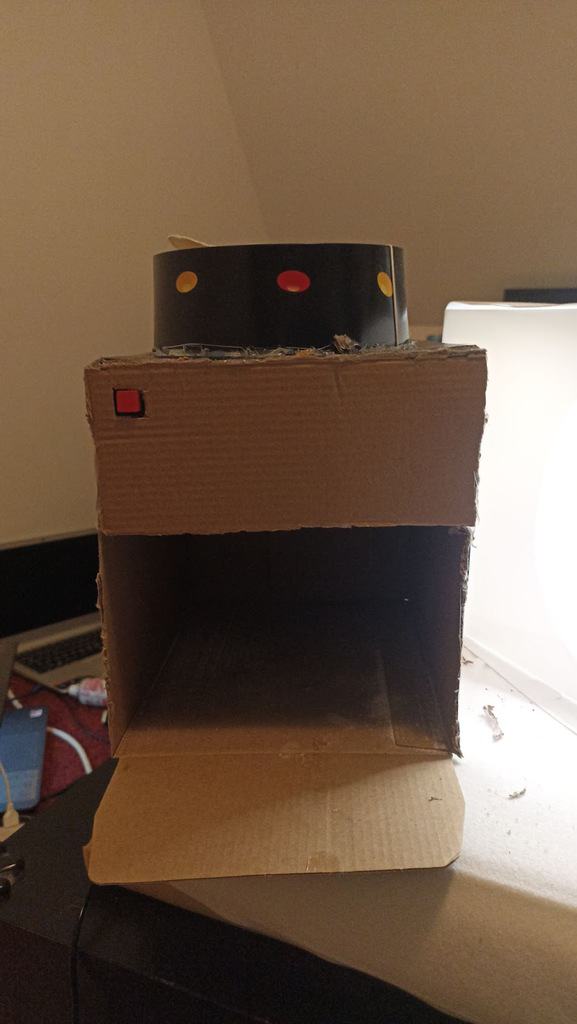
The Finished 555 Police Siren Circuit

For this project, I recommend trying different values for the capacitors that control the 555 circuits, and the base of the transistor. Each capacitor will affect the sound in different ways: C2 will affect the oscillation of the sound, C3 is going to affect the curve in which the sound changes, and C4 will change the range of the pitch in which the siren is going back and forward.

If you take C3 out of the board completely, you will notice how the sound changes in an abrupt manner, since there is no capacitor softening the frequency change.

Be careful with C2, since having a very low capacitor may change the oscillation into just a straight sound, on the contrary, a too high capacitor will make the changes too slow. In the video displayed above, the capacitors are different from the ones in the schematic, so you will hear a slightly different sound in your project.

Copyright Build Electronic Circuits

Thursday 26 May 2022

How to Build a Touch Sensor Circuit

In this project, you will build a touch sensor circuit. It’s a cool and simple circuit that allows you to control an LED with the touch of a finger. And you only need three components, how cool right?

You can build this circuit if you’re a total beginner.

The Touch Sensor Circuit Diagram

You only need a resistor, a transistor, and an LED to build this project. Below you’ll find the schematics for the touch sensor circuit:

Touch sensor circuit schematic

Components Needed

  • 9V Battery
  • 9V Battery Clip
  • Breadboard
  • Jumper Wires
  • 470Ω Resistor
  • Red LED
  • NPN Transistor (BC546/547/548 or similar)

These are all standard components you can find at most electronics shops.

How It Works

Your body has electric resistance. You can check by measuring the resistance between your fingers with a multimeter.

So when you touch the wires of the touchpad, your body behaves as a resistor. This means a small amount of current can flow from the plus of the battery, through the transistor’s base, and turn on the transistor.

When the transistor is on, current can flow from collector to emitter of the transistor and the LED will turn on. Learn more about this in the article on how transistors work.

How to Build the Touch Sensor Circuit

You will build this circuit on a breadboard. But once you’ve tested that it works properly, feel free to go a step further and solder it.

Step 1: Connect The Transistor

Start by connecting the transistor a little bit down on the board.

If you’re using a BC546/BC547/BC548 transistor, you can connect it as shown in the figure. The collector goes into row 10, the base in row 11, and the emitter in row 12.

Note: If you have a different transistor model (ex the 2N3904), you need to check the datasheet to find out which leg is which, and adjust your connections accordingly.

Breadboard with transistor

Step 2: Connect The Resistor

Next, connect the resistor. Connect it from row 1 to row 9.

Notice that it is not connected to the transistor since the transistor is connected in row 10.

(In the following images, a 220 Ω resistor is shown. But it could be a good idea to use a larger value like a 470 Ω resistor to make sure your LED can handle the current.)

Breadboard with transistor and resistor

Step 3: Place The LED And Touchpad

Now, you’re going to connect the LED and the touch-sensing part. For the touch-sensing part, you’ll need two exposed wires. You can get this from the LED. The LED has much longer legs than needed.

Cut off the legs of the LED so that only around 1 cm / 0.4 in is left on the LED. Bend the two legs that you just cut off, as shown below, so that they fit in between four columns on a row.

LED with legs cut off to make touchpad

Place one on row 4 between column A and D. And one on row 6 between column A and D. This leaves room for a jumper wire to be connected later.

Insert the LED with its positive side on row 9 column F, and the other side on row 10 column F. Now the LED is connected between the resistor and the collector of the transistor, just like in the schematics of this circuit.

Breadboard with transistor, resistor, LED, and touchpad.

Step 4: Connect The Touchpad

Now you need to connect the two touch wires to the correct points in the circuit, using jumper wires.

Connect one jumper wire from row 1 column F to row 4 column E. And one jumper wire from row 6 column E to row 11 column I.

Breadboard with the touch sensor circuit connected, without power connections.

Step 5: Touch It!

Next, connect a jumper wire from row 1 column J to the positive supply column on the right. Then connect a jumper wire from row 12 column I to the negative supply column on the right.

Connect your battery connector and plug in the battery.

Breadboard with the complete touch sensor circuit connected to battery

If everything is connected properly, nothing should happen right now.

But then, try to touch the touch wires so that your finger touches both wires at the same time, and the light will turn on.

If you can’t see the light, try making the tip of your finger wet before touching again. When the skin of your finger is wet, the resistance decreases so that more current can flow through your finger and to the base of the transistor.

What If There Is No Light?

In this circuit there are three common errors:

  • the orientation of the LED is wrong
  • the orientation of the transistor is wrong
  • you are using a PNP transistor instead of an NPN transistor
  • your finger is too dry

The NPN and the PNP transistors look exactly the same, so the only way to distinguish them is to look at what is written on the transistor. If it says BC557, it’s a PNP transistor, which is *not* correct. If it says BC546 (or BC547 or BC548) it’s NPN and it’s correct.

If you tried all of the above and it’s still not working, check the resistance value of your resistor. It should be 470 Ω. If it’s much more, it restricts the current to the LED too much. If it’s much less, it might have broken the LED.

If you have any questions about this experiment, use the comment field below.

The Result

In the video below you can see the process of building this, and the final result showing the working circuit:

Copyright Build Electronic Circuits

Wednesday 25 May 2022

Artificial cilia could someday power diagnostic devices

Researchers have now designed a micro-sized artificial cilial system using platinum-based components that can control the movement of fluids at such a scale. The technology could someday enable low-cost, portable diagnostic devices for testing blood samples, manipulating cells or assisting in microfabrication processes.

Organic crystals can serve as energy converters for emerging technologies

New research demonstrates that organic crystals, a new class of smart engineering materials, can serve as efficient and sustainable energy conversion materials for advanced technologies such as robotics and electronics.

Tuesday 24 May 2022

A good defect? Researchers discover helicoidal screw dislocations in layered polymers

Researchers recently discovered a helicoidal-shaped defect in layered polymers, uncovering how solvents can diffuse through layers and produce color changes.

Monday 23 May 2022

Custom 'headphones' boost atomic radio reception 100-fold

Researchers have boosted the sensitivity of their atomic radio receiver a hundredfold by enclosing the small glass cylinder of cesium atoms inside what looks like custom copper 'headphones.'

Charging a green future: Latest advancement in lithium-ion batteries could make them ubiquitous

Lithium-ion batteries (LIBs) power electric vehicles and electronics. With the prevalence of these set to increase, efforts have been directed towards improving the performance and longevity of LIBs. Now researchers have shown that adding a specific polymer composite binder to the silicon anode of LIBs can improve its structural stability significantly, making it viable for much more powerful, long-lasting LIBs, and changing the future of the technologies it drives.

Thursday 19 May 2022

Is it topological? A new materials database has the answer

A new materials database reveals more than 90,000 known 'topological' materials with persistent electronic properties.

New thermal management technology for electronic devices reduces bulk while improving cooling

Electronic devices generate heat, and that heat must be dissipated. The high temperatures can compromise device function or even damage the devices and surroundings if it isn't. Now, a team has detailed a new cooling method that offers a host of benefits, not the least of which is space efficiency which offers a substantial increase over conventional approaches in devices' power per unit volume.

Spin keeps electrons in line in iron-based superconductor

Electronic nematicity, believed to be an important ingredient in high-temperature superconductivity, is primarily spin-driven in the iron-based superconductor FeSe, reveals a new study.

Synthesis of two-dimensional holey graphyne

A new type of carbon allotrope, holey graphyne, has semiconductor properties and is applicable in various fields such as photoelectronics, sensors, and water purification.

Wednesday 18 May 2022

Energy-efficient AI hardware technology via a brain-inspired stashing system?

Researchers have proposed a novel system inspired by the neuromodulation of the brain, referred to as a 'stashing system,' that requires less energy consumption. Computer scientists have now developed a technology that can efficiently handle mathematical operations for artificial intelligence by imitating the continuous changes in the topology of the neural network according to the situation.

Tuesday 17 May 2022

New silicon nanowires can really take the heat

A research team has demonstrated an ultrathin silicon nanowire that conducts heat 150% more efficiently than conventional materials used in advanced chip technologies. The device could enable smaller, faster, energy-efficient microelectronics.

Shaping the future of light through reconfigurable metasurfaces

Harnessing the power of 'phase-change' materials, researchers have demonstrated how reconfigurable metasurfaces -- artificial materials with extraordinary optical properties -- are crucial to the future of nanotechnology.

Monday 16 May 2022

Electronic skin: Physicist develops multisensory hybrid material

Recently developed 'smart skin' is very similar to human skin. It senses pressure, humidity and temperature simultaneously and produces electronic signals. More sensitive robots or more intelligent prostheses are thus conceivable.

Thursday 12 May 2022

Researchers develop wireless implantable vascular monitoring system

Researchers are improving the odds for patients with the development of an implantable soft electronic vascular monitoring system. Their smart stent and printed soft sensors, is capable of wireless real-time monitoring of hemodynamics without batteries or circuits.

Wednesday 11 May 2022

Researchers find way to form diodes from superconductors

Researchers have demonstrated how a heterostructure consisting of superconductors and magnets can be used to create uni-directional current like that found in semiconductor diodes.

Tuesday 10 May 2022

Spintronics: How an atom-thin insulator helps transport spins

An intermediate layer consisting of a few atoms is helping to improve the transport of spin currents from one material to another. Until now, this process involves significant losses. A team reports on how this can be avoided. The researchers thus demonstrate important new insights relevant for many spintronic applications, for example energy-efficient and ultra-fast storage technologies of the future.

Monday 9 May 2022

Multi-tasking wearable continuously monitors glucose, alcohol, and lactate

Imagine being able to measure your blood sugar levels, know if you've had too much to drink, and track your fatigue during a workout, all in one small device worn on your skin. Engineers developed a prototype of such a wearable that continuously monitors several health stats at once.

Energy researchers invent chameleon metal that acts like many others

Researchers have invented a groundbreaking device that electronically converts one metal into behaving like another to use as a catalyst for speeding chemical reactions.

Friday 6 May 2022

Powerful family of two-dimensional materials discovered

A team has developed a new family of two-dimensional materials that researchers say has great potential for many applications such as batteries and supercapacitors, catalysis, sensors and electronics.

Thursday 5 May 2022

Mechanism 'splits' electron spins in magnetic material

Holding the right material at the right angle, researchers have discovered a strategy to switch the magnetization in thin layers of a ferromagnet -- a technique that could eventually lead to the development of more energy-efficient magnetic memory devices.

Automated synthesis allows for discovery of unexpected charge transport behavior in organic molecules

A cross-disciplinary team has demonstrated a major breakthrough in using automated synthesis to discover new molecules for organic electronics applications. Using automated synthesis, the team was able to rapidly scan through a library of molecules with precisely defined structures, thereby uncovering, via single-molecule characterization experiments, a new mechanism for high conductance.

Tuesday 3 May 2022

Project: A DIY Sugar Dispenser

In this guide, I’ll show you how to build a DIY sugar dispenser using parts made of cardboard.

By making the parts out of cardboard, it’s quick and easy to build and experiment with different ways to have your machine dispense sugar.

When you’ve built a cardboard-based sugar dispenser that you’re happy with, you can consider upgrading it by building the mechanics using other more durable materials (ex laser cutting plastic).

But for now, let’s build our cardboard prototype!

Sugar Dispenser Circuit

In the following image, you can find the schematics of the circuit you are going to connect.

Schematic showing how to connect a button and a servo motor to arduino
The schematic for this project

The button and the servo motor are the two primary parts of the circuit. The button part will allow you to control the amount of sugar in a cup.

The servo motor has three pins; 5V, GND, and PWM. You need to connect the PWM pin to an Arduino pin that can output PWM signals, such as D9.

Making a box for the sugar dispenser is the most difficult part of this project. You may create it the way I did below, or use your own design. Either way, you’ll put your engineering skills to the test =)

Necessary Components

  • Arduino Uno
  • Micro Servo Motor
  • Button
  • 10kΩ resistor
  • Blank perfboard
  • Jumper wires
  • 2 x cardboard boxes
  • Pin header socket with four pins
  • Elastic band
  • 9V battery or adapter for Arduino powering

Necessary Tools

  • Soldering Iron
  • Hot glue gun

How It Works

The servo motor opens or closes the sugar dispenser using a little piece of cardboard that moves over a hole.

The servo motor is controlled by the Arduino and will open the sugar dispenser whenever you push the button. When you release the button, the Arduino moves the servo back and closes the hole.

Building The Circuit

We’ll start by soldering the button, the resistor, and the pin header on a perfboard. Then we’ll connect the servo and power supply. And finally, we’ll upload the code.

Creating the Button Board

In this step, you are going to make a button that you will use to control the amount of sugar.

Take a blank perfboard and solder a button to it.

Button soldering – front
Button soldering – back

Take the pin header socket and solder it beside the button. You can use either male or female, you just need the opposite version for your jumper wires:

Pin header socket soldering – front
Pin header socket soldering – back

Solder the closest pin of the socket with the closest pin of the button. This will be connected to the Arduino in a later step:

Connecting the button to the pin

Next, solder the upper button pin with pins 2 and 3 on the socket. On this pin, you will connect the Vcc (5V) in a later step.

Connecting the button to the pin

Take your resistor and solder it to the PCB:

Resistor soldering – front
Resistor soldering – back

Solder one pin of the resistor to a free pin of the button. And the second leg of the resistor to the remaining pin of the socket. This will be the GND pin.

Connecting the resistor with the button

You have your button ready for the machine!

Next, connect everything to the Arduino. Take your Arduino Uno and the board you just made and make the following connections:

  • Connect the rightmost header pin on your button board (PWM) with pin 2 on the Arduino
  • Connect the third pin from the right (5V) to 5V on the Arduino
  • Connect the fourth pin from the right (GND) to the GND on the Arduino
Connecting PCB with the Arduino

Connecting the Servo Motor

The highlight of this project is the Servo Motor. It is a small, light server motor with high output power. The servo can spin around 180 degrees (90 in each direction). It comes with three wires: power, ground, and signal.

Micro Servo Motor

Just for simplicity, the connections made in the previous step are removed from the following image, but you shouldn’t remove anything. Make the following connections:

  • The signal wire (orange) of the servo motor connects to pin 9 of the Arduino
  • The power wire (red) of the servo motor connects to the remaining pin of the header socket on your button board
  • GND wire (brown) of the servo motor connects to the GND on the Arduino
Servo Motor Connections

In the following image, we can see the whole circuit connected together:

Finished Circuit

There is one remaining thing left for the circuit part to be finished, and that’s powering of Arduino. You can use a battery that you will connect to the Vin pin of the Arduino, or an adapter, in this case, I used an adapter.

Code

Copy and paste the following code into your Arduino IDE. Compile and upload it to your Arduino. When uploading code to the Arduino, don’t forget to disconnect the power to the Arduino as it will be powered through the cable connected to your computer instead.

Note: you need to include the Servo library in the code

#include <Servo.h> //including servo library
int button = 2; //button pin
int press = 0; //variable to check if the button is pressed
int previous = 0; //variable to check the previous state of the button
Servo servo; 

void setup()
{
  pinMode(button, INPUT); //setting button as the input 
  servo.attach(9); //pin for servo control signal
}

void loop()
{
  press = digitalRead(button); //putting the state of the button into "press" variable, if it is pressed "press" variable will have value 1, otherwise 0
  if (press == HIGH) //checking if the button is pressed
  {
    if (!previous) { //checking if the button was not pressed in the previous state
      servo.write(80); //if the button was not pressed, then will rotate servo motor
    }
    previous = 1; //setting "previous" value to 1 because the button is pressed
  }
  else{ //case when the button is not pressed
    if (previous) { //if the button in the previous step was pressed and not pressed anymore
      servo.write(30); //rotating servo back
    }
    previous = 0; //setting "previous" value to 0 because button was not pressed
  }
  delay(200); //short delay
}

Making The Machine

This, I believe, is the most difficult stage in the project, and it is here that we will put our engineering skills to the test. This was my approach to and solution to the problem; if you have a better idea, please feel free to do it differently.

Start with using some box and use a hot glue gun to glue some flat cardboard on the top of the box.

Empty box

In the next step glue the servo motor to the edge of the box, and make sure you screw the horn (arm) to it before:

Servo glued to the box

Make a small hole on the cardboard for the sugar to flow through. Then take another piece of the cardboard, rectangular shape, with the end of it glued to the arm of the servo. You can secure it more using an elastic band.

It should be connected in such a way that the servo can move it to cover or uncover the hole below. Check out the following video to see how this part should work:

Now take the greater box, on top of it cut the circle shape, and insert the box you already made up to half. It should look like this:

You could have a functional dispenser right here, but I wanted to make it more professional looking for my kitchen, so I took the extra rectangular cardboard, make a square hole size for the button on it, and on the other side of that cardboard place your Arduino and PCB with the button.

Electronics on the cardboard

In this step, you should insert the power for Arduino, either battery or adapter, and once again use a hot glue gun to glue this part to the box.

The Final Box

And that is the last step, put something in the box (ex. sugar, rice, oats..), place a mug under, press the button, and enjoy!

The Result

Copyright Build Electronic Circuits

New circuit boards can be repeatedly recycled

Researchers have developed a new PCB that performs on par with traditional materials and can be recycled repeatedly with negligible material...