Friday, 30 September 2022
Researchers develop ultra-strong aerogels with materials used in bullet-proof vests
Neural net computing in water
Thursday, 29 September 2022
Fluidic circuits add analog options for controlling soft robots
3D printing can now manufacture customized sensors for robots, pacemakers, and more
Saturday, 24 September 2022
Reduced power consumption in semiconductor devices
Thursday, 22 September 2022
Key element for a scalable quantum computer
Smart microrobots walk autonomously with electronic 'brains'
Soft devices--powered by 'stressed' algae -- glow in the dark when squished or stretched
Wednesday, 21 September 2022
Voltage Divider Tutorial For Beginners
A voltage divider is a circuit that creates a smaller voltage from an input voltage by using two resistors. You’ll see it in both simple and advanced circuits all the time. Here’s the basic setup:
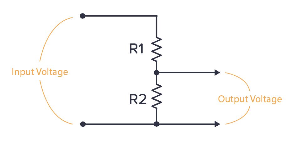
It is useful for example for reading sensors like thermistors and photoresistors since it converts an unknown resistance into a voltage. Or to reduce the volume of an audio signal via a potentiometer.
You can find the output voltage by inserting the resistor values and the input voltage into the following formula:

Or you can use the calculator a little bit further down on this page.
Once you know how it works, it’s much easier to see how circuits work. And it will let you calculate voltages at many different points in a circuit – which is often needed to understand it.
Voltage Divider Formula
This formula is one of the few electronics formulas (in addition to Ohm’s law) that I use on a regular basis.
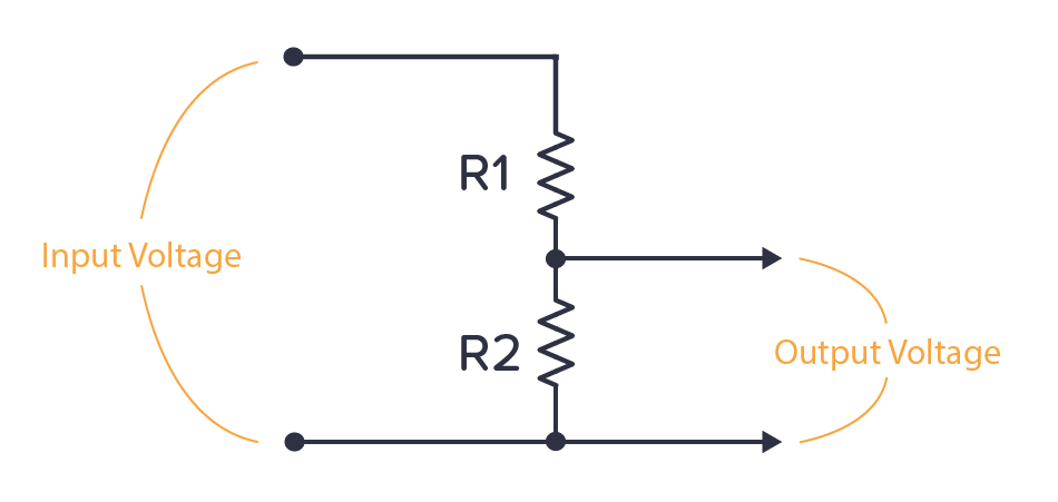
It’s for finding the output voltage when you have two resistors connected like this:
The formula for calculating the output voltage is:
This can be a useful formula to remember. It will come in handy often. Or use the voltage divider calculator below if you prefer the easy way ;)
Voltage Divider Calculator
Fill in the input voltage and resistor values in the voltage divider calculator below to find the output voltage:
We’ve added this calculator to a practical voltage divider calculator page that you can bookmark and come back to in the future.
Where Do You Find The Voltage Divider?
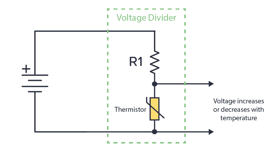
One example of a voltage divider circuit is for reading analog sensors. For example, the thermistor is a temperature sensor. It changes its resistance based on the temperature. If you connect it with a known resistor value in a voltage divider setup, you’ll get a voltage that depends on temperature:
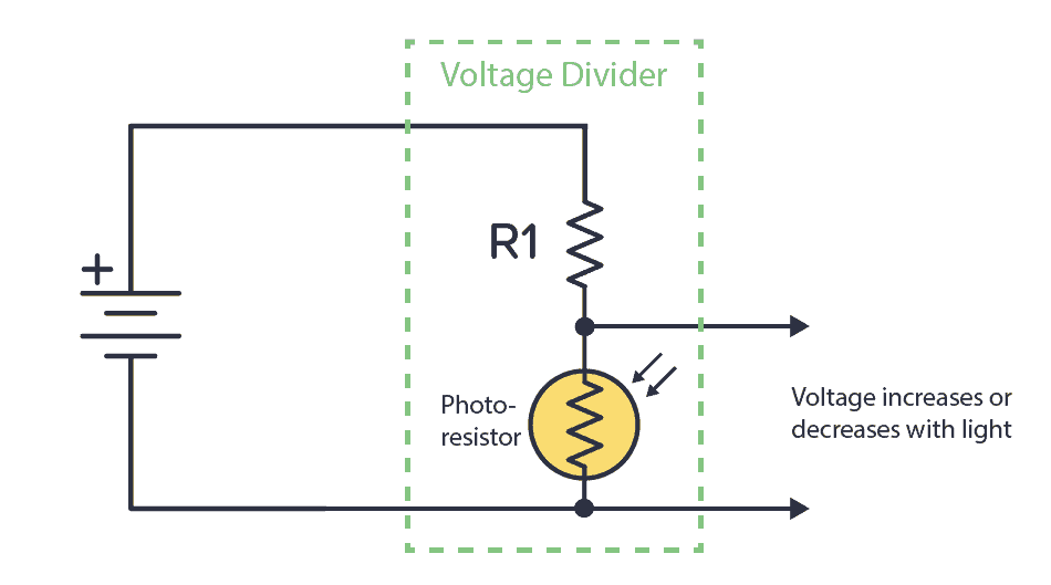
Or you can combine a known resistor with a photoresistor. The photoresistor changes resistance based on the amount of light it detects. This way, you have a circuit that increases or decreases the voltage based on light.
You can connect the output of any of these circuits into a comparator to check it’s above or below a certain voltage. Then do something based on that. For example, if the temperature is above 40 degrees, turn on a fan.
Or connect into an analog pin of an Arduino or a microcontroller and do cool stuff with it. Maybe turn on a light if the photocell indicates that it’s dark?
Calculation Example: Different resistor values
Let’s say we have the following values:


By using the formula above we get

Calculation Example: Equal resistor values
Now, let’s say R1 and R2 has the same value.


By using the formula above we get

This means that when the two resistors have the same value, the output is always half the input.
Can You Use Voltage Divider as a Power Supply?
If you have a circuit that needs 4.5 V, could you use a voltage divider with two 500 Ω resistors to get 4.5 V from your 9V battery?
Unfortunately, it’s not that easy.
Any circuit you want to power will have an internal resistance. So from the perspective of the voltage divider, whatever circuit you connect to the voltage output can be seen as a resistor (RLOAD) connected in parallel with R2.
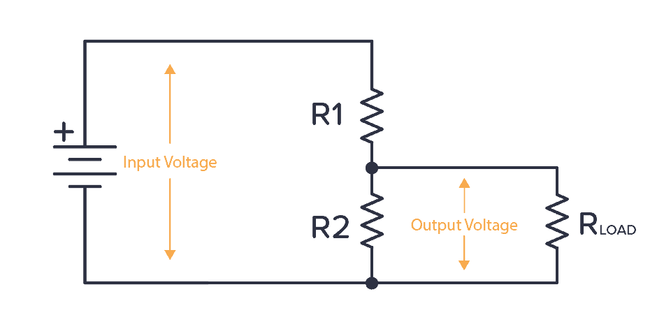
If the internal resistance of the circuit (RLOAD) is also 500 Ω, what happens?
Now, the R2 from the voltage divider formula becomes the parallel resistance of R2 and RLOAD. Which is just 250 Ω. If you put this into the voltage divider formula, you get an output voltage of 3V instead of the 4.5V you wanted.
For a power supply, you want the voltage to stay at the chosen level no matter if the circuit you connect has a high or low internal resistance. That’s why the voltage divider is not commonly used for power supplies.
Instead, you need to use a voltage regulator.
Questions?
What are your questions about the voltage divider? Let me know in the comment section below.
Copyright Build Electronic Circuits
Thursday, 15 September 2022
NOT Gate (Inverter) – Logic Gates Tutorial
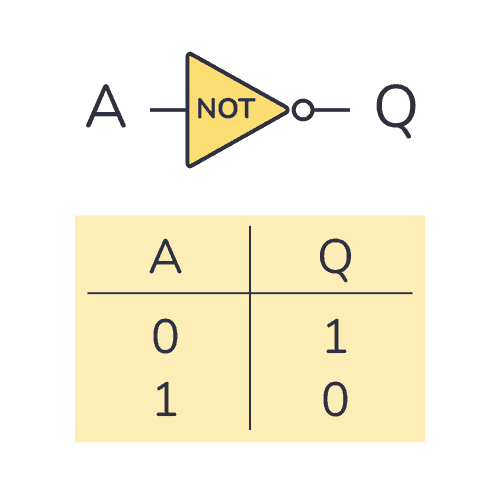
A NOT gate (or inverter) is a logic gate where the output is the opposite of the input. So you can say that the output is NOT the same as the input. It’s often called an inverter since it inverts the input.
The schematic symbol for an inverter is like a buffer, just with a circle at the output to indicate that it’s an inverted version of the input.
The logic or Boolean expression for a NOT gate is  which means that:
Q is the opposite of A
Truth Table
A NOT gate can only have one input. And its truth table is pretty simple since there are only two possible states; the input being HIGH (or “1”) or the input being LOW (or “0”).
NOT Gate Truth Table

| Input A | Output Q |
|---|---|
| 0 | 1 |
| 1 | 0 |
Build an Inverter with Transistor-Resistor Logic
You can build an inverter/NOT gate from transistors and resistors. This technique is called resistor-transistor logic (RTL).
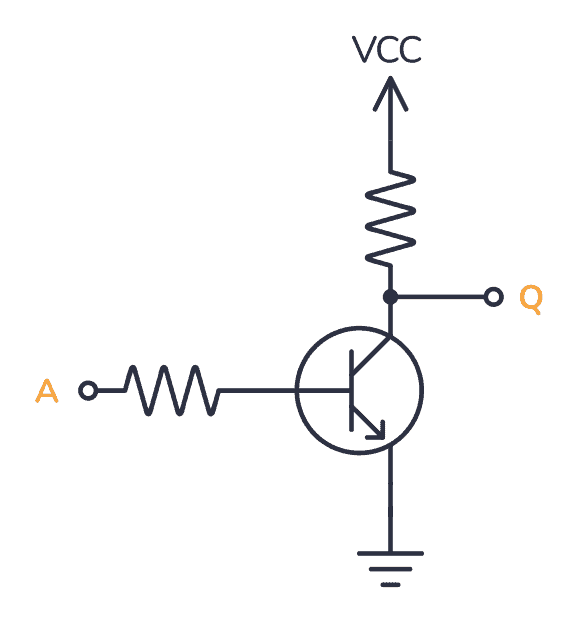
If A is HIGH, the transistor turns on. When the transistor is turned on, Q is pulled LOW through the transistor. If A is LOW, the transistor is off and Q is pulled HIGH through the resistor up to VCC.
It’s fun to know how you could build it with transistors and resistors. But it’s not really practical to use that many components just to make a simple logic gate. Luckily, there are many ICs that have NOT gates that you can use out-of-the-box.
IC Alternatives with NOT Gates/Inverters

If you want to experiment and build circuits with NOT gates, you’ll find them in both the 4000 IC series and the 7400 IC series:
- 4041: Four NOT gates/inverters (with buffers)
- 4049: Six NOT gates/inverters
- 4069: Six NOT gates/inverters
- 40106: Six NOT gates/inverters with Schmitt trigger
- 4572: Four NOT gates/inverters (plus a few other gates)
- 74HC04: Six NOT gates/inverters (HC is the family, can also be LS/HCT/…)
- 74HC05: Six NOT gates/inverters (HC is the family, can also be LS/HCT/…)
- 74HC14: Six NOT gates/inverters with Schmitt trigger (HC is the family, can also be LS/HCT/…)
These should all be available as hobbyist-friendly through-hole chips. Just make sure you buy the DIP package version.
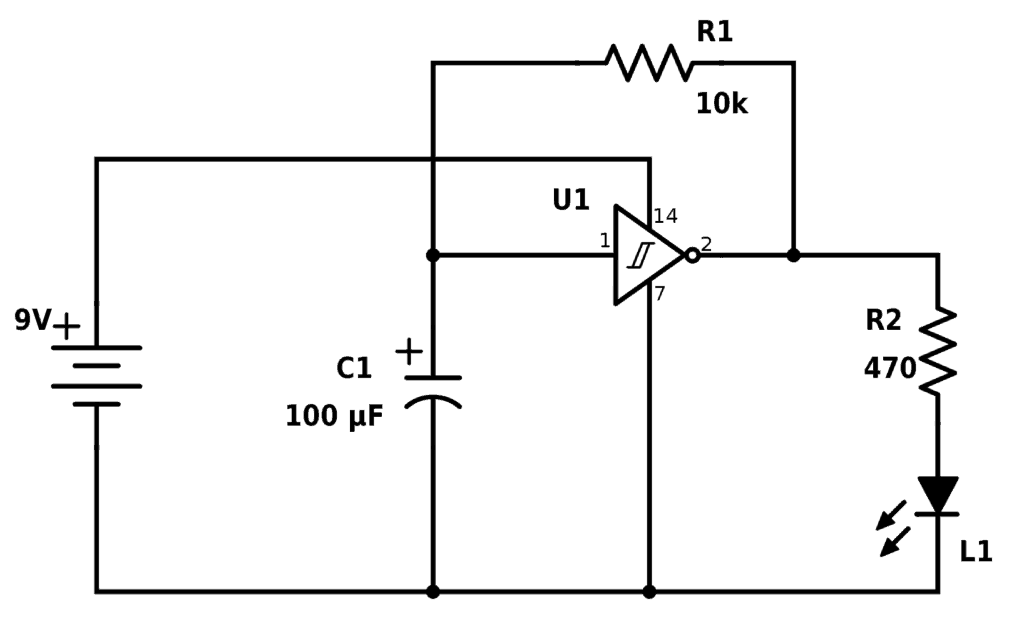
Inverter Example Circuit: Blinking LED
A fun circuit to build with inverters is the blinking LED circuit. In the following circuit, the Light-Emitting Diode (LED) is blinking continuously. Note that this circuit will only work with Schmitt trigger inverters. So you can build it for example with the CD40106B chip or the 74C14 chip.
The resistor R1 and the capacitor C1 sets the blinking speed.
Next Step in the Logic Gates Tutorial
Check out the other articles in this logic gates tutorial:
NOT Gate/Inverter – (You are here)
AND Gate
NAND Gate
OR Gate
NOR Gate
XOR Gate
XNOR Gate
Back to the Logic Gates Overview
Copyright Build Electronic Circuits
XNOR Gate – Logic Gates Tutorial
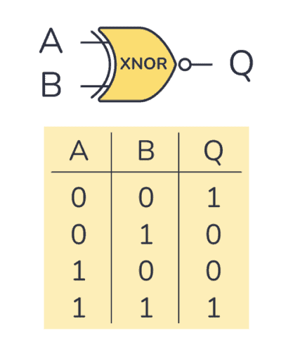
An XNOR gate is a logic gate where the output goes HIGH (or “1”) only if both its inputs are equal. So if the inputs A and B are both HIGH or both LOW, the output Q will be HIGH.
The logic or Boolean expression for an XNOR gate is  which means that:
If A and B are the same, then Q is true
Truth Table
XNOR gates commonly only have two inputs. It will only give out a HIGH or logic “1” if both its inputs are equal. So the inputs must both be HIGH or both be LOW for the output to become HIGH.
XNOR Gate Truth Table

| Input A | Input B | Output Q |
|---|---|---|
| 0 | 0 | 1 |
| 0 | 1 | 0 |
| 1 | 0 | 0 |
| 1 | 1 | 1 |
IC Alternatives with XNOR Gates
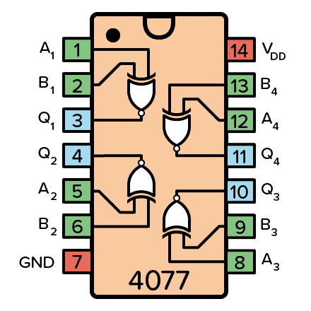
If you want to experiment and build circuits with XNOR gates, you’ll find them in both the 4000 IC series and the 7400 IC series:
- 4077: Four XNOR gates
- 74HC266: Four XNOR gates (HC is the family, can also be LS/HCT/…)
These should all be available as hobbyist-friendly through-hole chips. Just make sure you buy the DIP package version.
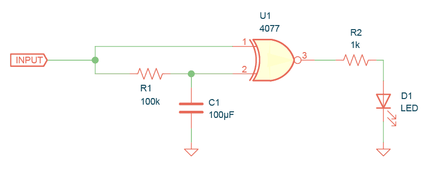
Example Circuit: XNOR Gate Edge Detection
This circuit detects if a signal is going from LOW to HIGH or from HIGH to LOW. The Light-Emitting Diode (LED) on the output turns on for a short amount of time when an edge is detected.
For fast-switching signals, you’d need lower values for R1 and C1, and the LED would be ON for such a short time that it wouldn’t make sense. But instead, it would make sense to for example read the output into a microcontroller, or use a counter to count the edges.
Next Step in the Logic Gates Tutorial
Check out the other articles in this logic gates tutorial:
AND Gate
NAND Gate
OR Gate
NOR Gate
XOR Gate
XNOR Gate – (You are here)
Back to the Logic Gates Overview
Copyright Build Electronic Circuits
Wednesday, 14 September 2022
Making mini-magnets
Tuesday, 13 September 2022
Intriguing material property found in complex nanostructures could dissipate energy
Thursday, 8 September 2022
Logic Gates And How They Work

Logic gates are the basic building blocks of digital electronics. These are the components that we use for “doing stuff” with the 1s and 0s. You can combine them to create other building blocks like flip-flops, adders, and more.
The basic logic gates are AND, NAND, OR, NOR, XOR, XNOR, and NOT.
AND gate
The AND gate takes two (or more) inputs and gives out a 1 (HIGH/true) if all the inputs are 1. Otherwise, it gives out a 0 (LOW/false).
The truth table is below, but all you really need to remember is that the AND gate needs a 1 on input A and input B to give out 1.

| Input A | Input B | Output Y |
|---|---|---|
| 0 | 0 | 0 |
| 0 | 1 | 0 |
| 1 | 0 | 0 |
| 1 | 1 | 1 |
If you want to use it in a circuit, the IC 4081 contains 4 AND gates.
NOT gate/Inverter
The simplest logic gate of all is the NOT gate. It takes one bit as input (A). And it gives as an output (Y) what is NOT on the input. So if there is a 1 on the input, its output is 0. And if there is 0 on the input, its output is 1. It’s also called an inverter.

| Input (A) | Output (Y) |
|---|---|
| 0 | 1 |
| 1 | 0 |
If you want to use a NOT gate in your circuit, you can for example use the IC 4572 or IC 40106.
OR gate
The OR gate takes two (or more) inputs and gives out a 1 if any of the inputs are 1. Otherwise, it gives out a 0.
The truth table is below, but all you really need to remember is that the OR gate needs a 1 on input A or input B to give out 1.

| Input A | Input B | Output Y |
|---|---|---|
| 0 | 0 | 0 |
| 0 | 1 | 1 |
| 1 | 0 | 1 |
| 1 | 1 | 1 |
If you want to use it in a circuit, the IC 4071 contains 4 OR gates.
NAND gate
The NAND (or NOT AND) gate operates in the opposite way of the AND gate. It’s like if an AND gate had a NOT gate on its output:

You’ll find the truth table below. But all you need to remember is that the only time the output of a NAND gate is 0 is when both the inputs are 1.

| Input A | Input B | Output Y |
|---|---|---|
| 0 | 0 | 1 |
| 0 | 1 | 1 |
| 1 | 0 | 1 |
| 1 | 1 | 0 |
If you want to use NAND gates in a circuit, the CMOS IC 4011 contains 4 NAND gates.
NOR gate
The NOR (or NOT OR) gate operates in the opposite way of the OR gate. It’s as if an OR gate had a NOT gate on its output.

You’ll find the truth table below. But all you need to remember is that the only time the output of a NOR gate is 1 is when both the inputs are 0.

| Input A | Input B | Output Y |
|---|---|---|
| 0 | 0 | 1 |
| 0 | 1 | 0 |
| 1 | 0 | 0 |
| 1 | 1 | 0 |
If you want to use NOR gates in a circuit, the IC 4001 contains 4 NOR gates.
XOR gate
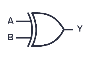
The XOR (or Exclusive OR) gate outputs 1 if one of its two inputs is 1 – but not both. You can also look at it in this way – if the two inputs are different from each other, the output is true.
| Input A | Input B | Output Y |
|---|---|---|
| 0 | 0 | 0 |
| 0 | 1 | 1 |
| 1 | 0 | 1 |
| 1 | 1 | 0 |
If you want to use XOR gates in a circuit, the IC 4070 contains 4 XOR gates.
XNOR gate

The XNOR (or Exclusive NOT OR) gate works like an XOR gate with an inverter on the output. Another way to look at it is to notice that the output becomes 1 if its two inputs are equal – either two 1s or two 0s.
| Input A | Input B | Output Y |
|---|---|---|
| 0 | 0 | 1 |
| 0 | 1 | 0 |
| 1 | 0 | 0 |
| 1 | 1 | 1 |
If you want to use XNOR gates in a circuit, you’ll find four of them in the IC 4077.
Using Logic Gates in Circuits
A logic gate can be built with transistors and usually comes as an Integrated Circuit (IC).
There are two classic IC series that contain a lot of the same functions; the 7400-series and the 4000-series.
The 7400-series is the oldest series. The 4000-series was introduced as a lower-power and more versatile option to the 7400. But today, several families of the 7400-series exist, some with similar properties as the 4000-series.
Check out my list of common 4000 series IC with pinouts, explanations, and example circuits for more info.
Complete list of ICs in the 4000-series (Wikipedia)
Complete list of ICs in the 7400-series (Wikipedia)
Copyright Build Electronic Circuits
Modified microwave oven cooks up next-gen semiconductors
Scientists see spins in a 2D magnet
Converting 3D-printed polymer into a 100-times stronger, ductile hybrid carbon microlattice material
Wednesday, 7 September 2022
Robo-bug: A rechargeable, remote-control cyborg cockroach
Ohms Law – The Complete Beginner’s Guide
Ohms law is a simple formula that makes it easy to calculate voltage, current, and resistance. You can use it to find what resistor value you need for an LED. Or to find out how much power your circuit uses.
This is one of the few formulas in electronics that you’ll use on a regular basis. In this guide, you’ll learn how it works and how to use it. And I’ll also show you an easy way to remember it.
The law was found by Georg Ohm and shows how voltage, current, and resistance are related. Check out this Ohm’s law cartoon below to see how they relate:

Look at the drawing above and see if it makes sense to you that:
- If you increase the voltage (Volt) in a circuit while the resistance is the same, you get more current (Amp).
- If you increase the resistance (Ohm) in a circuit while the voltage stays the same, you get less current.
Ohm’s law is a way of describing the relationship between the voltage, resistance, and current using math:
V = R * I
- V is the symbol for voltage.
- I is the symbol for current.
- R is the symbol for resistance.
I use it VERY often. It is THE formula in electronics.
You can switch it around and get R = V/I or I = V/R. As long as you have two of the variables, you can calculate the last.
Ohm’s Law Triangle
You can use this triangle to remember Ohm’s law:
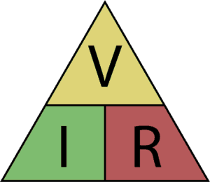
How to use it:
Use your hand to cover the letter you want to find. If the remaining letters are over each other, it means dividing the top one with the bottom one. If they are next to each other, it means multiply one with the other.
Example: Voltage
Let’s find the formula for voltage:

Place your hand over the V in the triangle, then look at the R and the I. I and R are next to each other, so you need to multiply. That means you get:
V = I * R
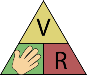
Example: Resistance
Let’s find the formula for resistance:
Place your hand over the R. Then you’ll see that the V is over the I. That means you have to divide V by I:
R = V / I
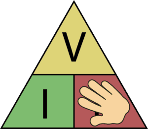
Example: Current
Let’s find the formula for current:
Place your hand over the I. Then you’ll see the V over the R, which means dividing V by R:
I = V / R
Quick Tip: How to Remember Without the Triangle?
A simple way of remembering things is to make a stupid association with it so that you remember it because it’s so stupid.
So to help you remember Ohm’s law let me introduce the VRIIIIIIII! rule.
Pretend that you’re driving a car really fast, then suddenly you hit the brakes really hard. What sound do you hear?
“VRIIIIIIIIIIII!”
And this way you can remember V=RI ;)
Example: Using Ohm’s Law to Calculate Current in a Circuit
The best way to learn how to use Ohm’s law it is by example.
Below is a very simple circuit with a battery and a resistor. The battery is a 12-volt battery, and the resistance of the resistor is 600 Ohms. How much current flows through the circuit?
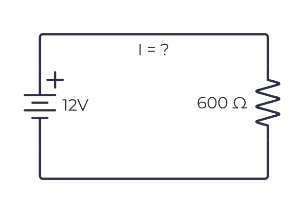
To find the amount of current, you can use the triangle above to the formula for current: I = V/R.
Now you can calculate the current by using the voltage and the resistance. Just type it into your calculator to get the result:
I = 12 V / 600 Ω
I = 0.02 A = 20 mA
So the current in the circuit is 20 mA.
Example: Choosing a Resistor for an LED
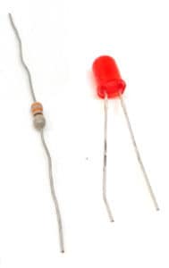
To safely power a Light-Emitting Diode (LED), you should always have a resistor in series with it to limit the current that can flow. But what value should you choose?
This is one of those practical situations where Ohm’s law becomes really useful.
Below you can see a typical LED circuit with a resistor in series. The LED grabs 2V from the battery, so the rest of the voltage (9V minus 2V = 7V) drops across the resistor. Let’s imagine that this LED can only handle up to 10 mA.
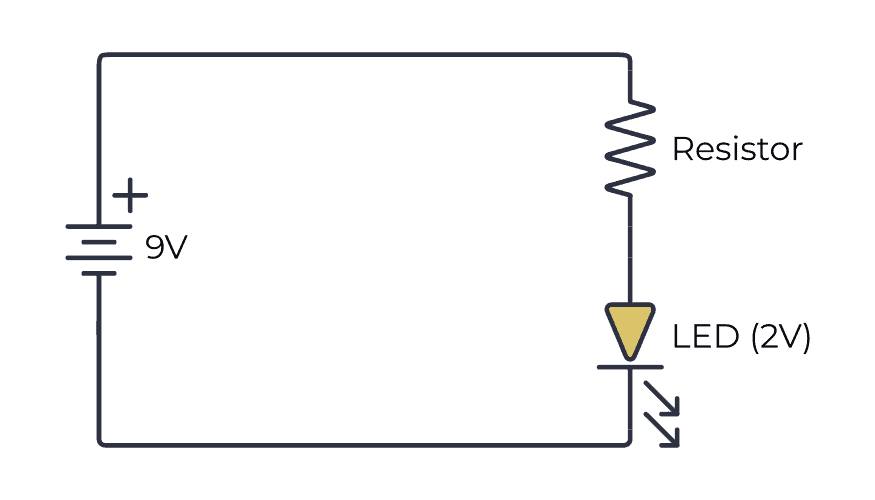
Since there is only one path for the current to take, the current through the resistor is the same as the current through the LED. So if you find the resistor value needed to get 10 mA through the resistor, then that’s what you’ll get through the LED as well.
The battery voltage is 9V. The voltage across the LED is 2V. So the rest of the battery voltage has to drop across the resistor. That means the voltage across the resistor is 7V.
And you want 10 mA (0.01A) through the resistor.
Plug this into the formula for finding resistance (see above), and you’ll get the needed resistor value:
R = V / I
R = 7 V / 0.01 A
R = 700 Ω
This means you need a resistor of 700 Ω to set the current to 10 mA.
Example: Figuring Out the Battery Voltage
Let us try another example.
Below we have a circuit with a resistor and a battery again. But this time we don’t know the voltage of the battery. Instead, we imagine that we have measured the current in the circuit and found it to be 3 mA (same as 0.003 A).
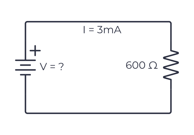
The resistance of the resistor is 600 Ω. What is the voltage of the battery?
By remembering the “VRIIII!” rule, you get:
V = R * I
V = 600 Ω * 0.003A
V = 1.8 V
So the voltage of the battery must be 1.8 V.
Copyright Build Electronic Circuits