Monday, 29 May 2023
Forging a dream material with semiconductor quantum dots
Friday, 26 May 2023
Snapshots of photoinjection
Tuesday, 23 May 2023
Electronic noses sniff out volatile organic compounds
Monday, 22 May 2023
Schottky Diode: A Beginner’s Guide
In this guide, you will discover what a Schottky diode is and how it can be used in electronic circuits.
Did you know that Schottky diodes, unlike other diodes, are formed by the junction of a semiconductor material with a piece of metal? That’s gives it some special properties that can come in handy.
What Is a Schottky Diode?
Diodes are components that normally only let current flow in one direction. Like a regular diode, the Schottky diode allows current to flow in the forward direction when enough forward voltage is applied.

However, while a regular PN junction diode is made by connecting p-type and n-type semiconductors, the Schottky uses metals like gold, tungsten, platinum, or aluminum instead of the p-type semiconductors.

This difference in construction gives it some unique properties that make it very useful for some specific applications. The Schottky diode has a relatively small voltage drop, usually between 0.15 to 0.45 V. This low forward voltage enables it to switch on and off much faster than traditional PN junction diodes.
How to Use Schottky Diodes
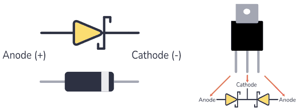
The Schottky diode works like any other PN junction diode, but faster. Current can flow through it only when it’s forward-biased. To make this happen, you must connect the anode to the most positive side and the cathode to the most negative side. Take a look at this example:
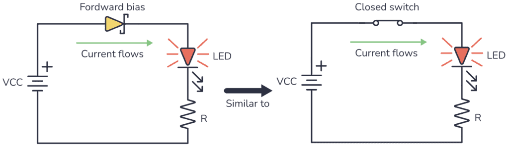
You can see above that the diode is forward-biased. That means the LED will light up because current can flow through it. When you use a Schottky diode like this, it’s like a fast switch that is closed and lets the current flow through the circuit.
Now let’s rotate the diode:
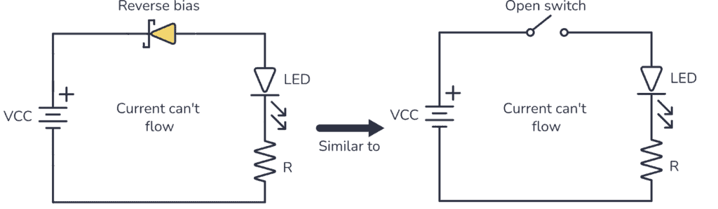
When the Schottky is reverse biased (cathode on the most positive side and anode on the most negative side) current can’t flow, so it acts like an open switch and the LED won’t turn on.
Schottky Diode vs PN Junction Diode
Schottky diodes are often compared to the PN junction diode. It’s because they behave very similarly. To understand the differences between them, take a look at their V-I characteristic curves:
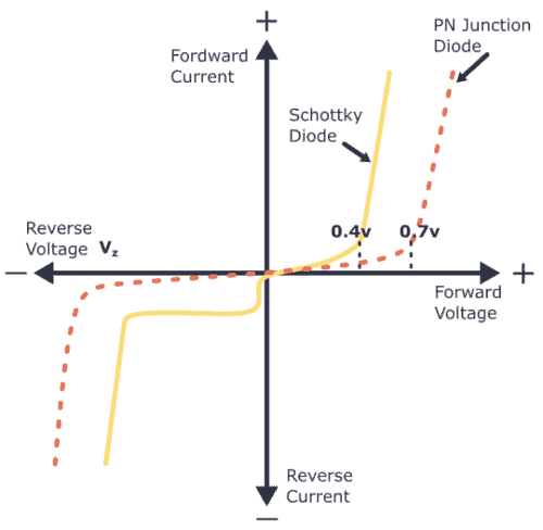
Consider that the curves above correspond to semiconductors made of silicon. You can see that the Schottky diode behaves a lot like a standard PN junction diode, except for one thing: the knee voltage – which is when it starts conducting – is much lower at around 0.4 V.
Thanks to its lower forward voltage drop, the Schottky diode can carry more current than a typical PN junction diode. The formula for power is power = volts x current (P = V*I). This means that a smaller forward voltage drop at a given current will result in less power dissipation than the PN junction diode. In plain English, the Schottky diode doesn’t get as hot as a regular diode.
Also, since Schottky diodes don’t have a p-type semiconductor, they have a low recovery time. This allows faster switching between on and off states.
Summary of Differences Between Schottky Diode and PN Junction Diode
| Schottky diode | PN junction diode |
|---|---|
| Formed by the junction of a piece of metal and an n-type semiconductor material | Formed by the junction of n-type and p-type semiconductor materials |
| Lower voltage drop | Higher voltage drop |
| Faster state change (on/off) | Slower state change (on/off) |
Applications of Schottky Diode
Some common applications of the Schottky diode include:
- Reverse current protection
- Solar cell applications
- Discharge protection
- Voltage clamping
- Switched-mode power supplies
- Logic gates circuits
- Radio frequency mixer and detector diodes
Schottky-clamped Transistor
A Schottky-clamped transistor is a type of BJT transistor. It has a Schottky diode connected across its base-collector junction and it is designed to switch on and off very quickly.
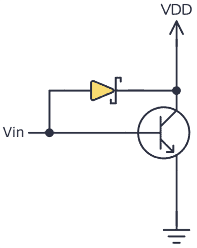
The Schottky diode in the transistor allows for faster switching by reducing the time it takes for the transistor to turn on and off. This is useful in applications where you need to switch things on and off rapidly. It also to helps reduce the amount of energy lost when the transistor is on, making the transistor more efficient. This means it can do its job while using less power.
Another advantage of a Schottky-clamped transistor is that it can handle voltage spikes and sudden changes in voltage without getting damaged. This makes it more reliable and durable in circuits where there might be fluctuations in voltage.
Schottky-clamped transistors are commonly used when you need fast switching and efficient operation, such as in power supplies, amplifiers, and digital circuits. They are especially good for applications involving radio signals and high frequencies.
Copyright Build Electronic Circuits
Thursday, 18 May 2023
Novel 3D printing method a 'game changer' for discovery, manufacturing of new materials
Tuesday, 16 May 2023
Milk reaction inspires new way to make highly conductive gel films
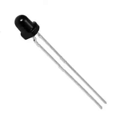
Phototransistor – A Newbie’s Guide
A phototransistor is an incredibly useful component for detecting light in electronics projects. You’ll often find them in remote-control receivers, pulse oximeters, and line-following robots.
In this guide, you will learn what phototransistors are, how to use one, and with a simple project you can build to create an automatic light on/off switch.
What Is a Phototransistor?
A phototransistor is a component that turns light into electricity. It is a type of transistor, just that it uses light instead of a base current to turn on and off. Its symbol looks like this:
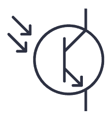
In a normal (BJT) transistor, the current from the base to the emitter controls the flow of current between the collector and emitter. In a phototransistor, light controls the flow of current between the collector and emitter.
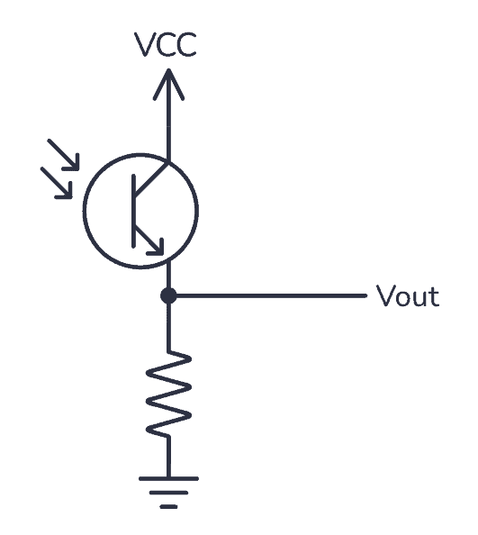
Below you can see a simple circuit that you can use to convert light into a voltage to test a phototransistor:
There are two different types of phototransistors, NPN and PNP. NPN phototransistors are the most common and are used for low-power applications, such as proximity sensors or optical encoders. PNP phototransistors are less common and are used for applications such as smoke detectors or IR sensors.
How Phototransistors Work
A phototransistor has a base, collector, and emitter like a regular transistor, but instead of a pin to connect to the base, it has an internal photodiode that converts light into current that acts as the base current.
Here’s a summary of the phototransistor working principle:
When light hits the photodiode, it produces a flow of electrons into the base of the transistor. This turns the transistor on so that current can flow from the collector to the emitter. The more light that hits the photodiode, the more electrons flow into the base, and the stronger the current becomes.
Phototransistor Circuit: Make an Automatic Light On/Off Switch
Now that you understand the basic concepts of a phototransistor, you can build an automatic switch that turns on a light when it’s dark. Since there is usually very little current flowing through a phototransistor, another transistor is used to turn on the light.
This project is a great way to learn about basic electronics, and you can easily expand on it. For example, by adding a relay or more powerful transistor to this circuit, you can control a much higher load, like a motor, and expand this into a light-following robot!
The Materials You’ll Need:
- Phototransistor
- 10 kΩ resistor (R1)
- 1 kΩ resistor (R2)
- BC547 or other NPN transistor (Q1)
- Light-Emitting Diode (LED)
- 9V Battery
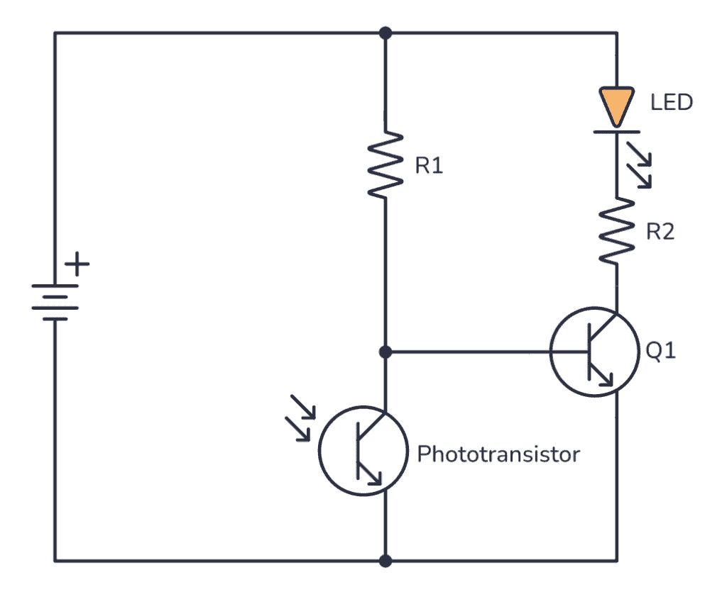
How It Works
Once you have made all the connections, the phototransistor should sense the ambient light level and output a signal to the NPN transistor. If the ambient light level is low, the NPN transistor will turn on and allow current to flow through the LED, turning the LED on. If the ambient light level is high, the NPN transistor will turn off and the LED will switch off.
The basic idea behind this circuit is that the phototransistor senses the amount of light falling on it and turns the LED on/off accordingly.
Phototransistors vs Photodiodes and Photoresistors
The main advantage of phototransistors over photodiodes and photoresistors is their high sensitivity to light. Because they have an in-built transistor that amplifies the current, they can detect very low levels of light.
They are also very fast, with response times of just a few nanoseconds, making them ideal for applications that require high-speed detection.
Phototransistors (and photodiodes) can be much smaller than a photoresistor, so you can fit hundreds into even small devices such as watches or calculators. And they consume less power.
Next Steps
There’s a lot of cool stuff you can do when you know how to use a phototransistor in your own projects. Some examples are robots, fridge-door alarms, invisible tripwires, and much more.
The best way to properly learn it is to just start using it. Build a few circuits with it to get a feel for how it works and try experimenting with your own design.
If you have any questions, let me know in the comment section below!
Copyright Build Electronic Circuits
Monday, 15 May 2023
With new experimental method, researchers probe spin structure in 2D materials for first time
Friday, 5 May 2023
Photodiode – A Beginner’s Guide
In this guide you are going to learn what a photodiode is, how it works, and more importantly, how you can use it in your own circuits. We’ll go through the basics, then build a fully working fire sensor circuit!

Did you know that there are two different ways to use photodiodes? Both of them are straightforward once you’ve learned them, but one is more common than the other.
Ok, let’s jump in!
What Is a Photodiode?
A photodiode is a diode that senses light. It has two legs and comes in various shapes and packaging. When light hits a photodiode, current flows through it in one of two ways: either a small current is created from the light, or the light allows a larger current to flow through.
The photodiode symbol looks like the symbol for the light-emitting diode, except that its arrows point inward.

How To Use a Photodiode
When you operate a photodiode without any bias voltage, shining light on it generates a small voltage across its terminals.

If you connect a resistor across it, a very small current flows through the resistor. This is called photovoltaic mode and works best in low-frequency conditions (i.e. when the light does not turn on and off really fast).

On the other hand, when it is reverse biased, i.e. the anode is connected to the negative voltage and the cathode to the positive voltage, it is in photoconductive mode. In this mode, it works more like a switch. Light on the photodiode “closes the switch” and current flows through the photodiode:

In this mode, it can switch on and off much faster. Photodiodes are usually used in this mode.
How Does a Photodiode Work?
Internally, a photodiode has a p-n junction, which is formed when a p-type semiconductor material is fused with an n-type semiconductor material. A p-type semiconductor material has holes as positive mobile charge carriers, while an n-type semiconductor material has electrons as negative mobile charge carriers.
Since the p-n junction has oppositely charged mobile carriers, they neutralize each other and form a depletion region at the juncture. It is called a depletion region because it is devoid of any mobile charge carriers. The part of the p-type material in the p-n junction is devoid of holes, so it becomes negatively charged. Similarly, the part of the n-type semiconductor in the p-n junction becomes positively charged.
When photons – or light – of sufficient energy fall on the p-n junction of the photodiode, they break and ionize the covalent bonds of the immobile atoms. This generates new electron-hole pairs. This phenomenon is called the photoelectric effect. The generated electrons are swept toward the n-type material (because the depletion region of the n-type material is positively charged). The holes are swept towards the p-type material (because the depletion region of the p-type material is negatively charged). This flow of charge leads to photocurrent or simply current.
In other words, a photodiode senses light and produces current as output. A photodiode is also called a photo sensor, photodetector, or light detector.
Your First Photodiode Circuit – a Fire Sensor
You can build your first photodiode circuit using just a few components. This circuit will sense fire and raise an alarm. The component list is:
- IR-range photodiode (any electronics component hardware shop will have one)
- BC547 transistor (or other general-purpose NPN transistor)
- Buzzer (Active)
- Light-Emitting Diode (LED)
- 470 Ω resistor (R1)
- 9V battery
- Breadboard

Connect this circuit on a breadboard as shown in the image below:

How This Circuit Works
When IR light (from a fire) falls on the reverse-biased photodiode, a current flows through it. This triggers the base terminal of the transistor. The BC547, which was previously off, switches on and starts conducting current between its collector and emitter terminals. This current also flows through the buzzer, producing an alarm, and triggering the LED to glow.
The LED-resistor pair is there to add a light indication in addition to the sound from the buzzer. If you want to keep the circuit simple, feel free to skip it.
Typical Photodiode Circuits
Photodiodes can be used in a variety of ways, but the most commonly used circuits are the two below that use operational amplifiers (op-amps).

In the photovoltaic circuit, you connect the photodiode in forward-biased mode. The anode of the photodiode is connected to the non-inverting terminal and the cathode to the inverting terminal of the op-amp. When light falls on the photodiode, it generates a small voltage and current. The op-amp amplifies this and outputs a voltage. The size of the voltage depends on the value of the feedback resistor RF.
In the photoconductive circuit, you connect the photodiode in reverse-biased mode. In the circuit diagram above, VR is a negative voltage. When light hits the photodiode, a small current passes through it, and an amplified voltage is available at the output.
In both cases, the op-amp is working as a trans-resistance amplifier or a current-to-voltage amplifier.
Types of Photodiodes
According to Byju, there are four types of photodiodes:
- PN photodiode: a simple p-n junction photodiode used in reverse-biased mode.
- PIN photodiode: a p-n junction photodiode with an intrinsic semiconductor layer between the p- and n-type material at the juncture. It is used when a greater surface area for light exposure is needed.
- Avalanche photodiode: a p-n junction photodiode that can be used in deep reverse-biased conditions. It has a higher photovoltaic current as a larger number of electron-hole pairs get generated in the p-n junction.
- Schottky photodiode: this is made of multiple Schottky diodes and operates at a higher speed and at larger wavelengths.
You can find photodiodes in most shops that sell electronic components. Check out our list of online electronic component shops.
What’s the Difference Between a Photodiode and a Phototransistor?
You may have come across the term phototransistor and wondered how it is different from a photodiode. If both are light-triggered devices, why are there two classes of such devices?
Well, photodiodes have one p-n junction and phototransistors have two p-n junctions. When light falls on the base of a phototransistor, it generates electron-hole pairs and allows current conduction in the base. Also, phototransistors are more sensitive to light than photodiodes. They generate more current than a typical photodiode.
Copyright Build Electronic Circuits
Monday, 1 May 2023
Tunneling electrons
-
CMOS (Complementary Metal Oxide Semiconductor) The main advantage of CMOS over NMOS and BIPOLAR technology is the much smaller power dis...
-
I was first introduced to logic gates when I was around 14 years old. I had heard that computers consisted of ones and zeroes. But I didn’t...
-
Bluetooth Controlled Electronic Home Appliances is a simple project, where we can control different electrical appliances and electronic de...


