Saturday, 7 July 2018

Arduino Flame Sensor Interface

In this project, we will see What is a Flame Sensor, what are the components of a Flame Sensor, how to connect a Flame Sensor with Arduino and How the Arduino Flame Sensor interface works?

Introduction

Flame Sensors, Smoke Sensors, Fire Alarms etc. are part of a safety equipment that help us in keeping our homes, offices and stores safe from fire accidents.

Almost all modern houses, apartments, malls, cinema halls, theatres, office buildings and shops are equipped with such safety equipment and it is mandatory in some regions to fire safety devices.
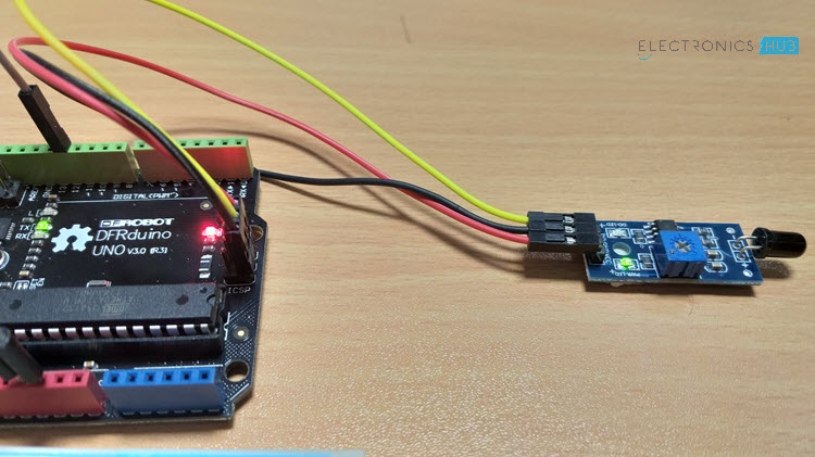
Arduino Flame Sensor Interface Image 2

Commercial fire safety devices are advanced with a lot of complex circuitry. If you want to implement a DIY Fire or Flame detection application, then this project might be helpful.

Warning: This project is just to give you an idea on how to implement a simple Flame Sensor using Arduino Platform and we do not guarantee its commercial applications.

A Brief Note on Flame Sensor

A Flame Sensor is a device that can be used to detect presence of a fire source or any other bright light sources. There are several ways to implement a Flame Sensor but the module used in this project is an Infrared Radiation Sensitive Sensor.

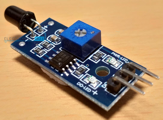
The following image shows an Infrared type Flame Sensor.
Arduino Flame Sensor Interface Flame Sensor

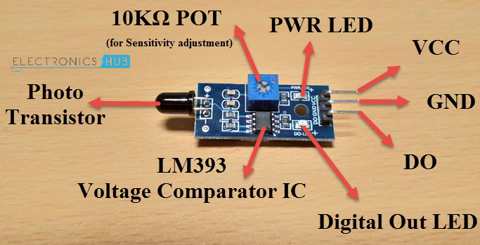
This particular flame sensor is based on YG1006 NPN Photo Transistor. The black object at the front of the module is this Photo Transistor.

The YG1006 Photo Transistor looks like a black LED but it is a three terminal NPN Transistor, where the long lead is the Emitter and the shorter one is the collector (there is no base terminal as the light it detects will enable the flow of current).

This photo transistor is coated with black epoxy, making it sensitive to Infrared radiations and this particular Photo Transistor (YG1006) is sensitive to Infrared Radiation in the wavelength range of 760nm to 1100nm.

Using this particular type of Flame Sensor, you can detect Infrared Light up to a distance of 100cm within its 60 degrees of detection angle.

There are two types of implementations of Flame Sensors using YG1006 Photo Transistor: one is with both Analog Output and Digital Output while the other is with only the Digital Output.

Both these implementations require same components but the difference is that one module (the one with the Analog Output) provides the Sensor output as Analog Output.

The Flame Sensor that I am using in this project has only Digital Output.

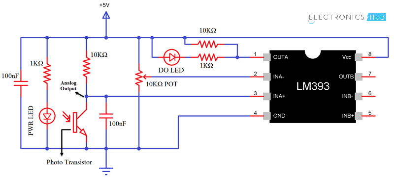
NOTE: In the circuit diagram of the Flame Sensor, I have pointed out where to get the Analog Output if your module doesn’t have that option.  

Components of Flame Sensor Module

The following image shows all the components of a typical Flame Sensor Module.
Arduino Flame Sensor Interface Flame Sensor Components

Circuit Diagram of Flame Sensor Module

If you want to know a little bit more about the Flame Sensor Module, then analyzing its circuit will probably help you. The following image shows the circuit diagram of a Flame Sensor.
Arduino Flame Sensor Interface Flame Sensor Circuit

Arduino Flame Sensor Interface

Whether you are using either of the Flame Sensors (with or without Analog Output), interfacing it with Arduino (or any other Microcontroller) is very easy. Since I do not have an Analog Output, I won’t go into that details.

By interfacing a Flame Sensor with Arduino, you can detect fire and activate a Buzzer (simple and easy implementation) or any other emergency safety measurements (like activating a sprinkler system or shutting off gas valves etc.).

Also read: SIMPLE FIRE ALARM CIRCUITS

Circuit Diagram of Arduino Flame Sensor Interface

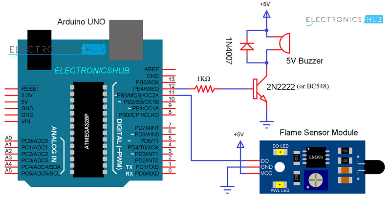
The following image shows the circuit diagram of the Arduino Flame Sensor Interface.
Arduino Flame Sensor Interface Circuit Diagram

Components Required

  • Arduino UNO
  • Flame Sensor
  • 2N2222 NPN Transistor (or BC548)
  • 5V Buzzer
  • 1N4007 PN Junction Diode
  • 1KΩ Resistor
  • Connecting Wires
  • Mini Breadboard
  • Power Supply

Circuit Design

Flame Sensor has three pins (some may have four pins): VCC, GND and DO. Connect VCC and GND to +5V and GND of the power supply (can be connected to Arduino’s +5V). the DO (short for Digital Output) is connected to Digital I/O Pin 11 of Arduino.

In order to indicate the detection of a flame or fire, a Buzzer is used. The Buzzer circuit consists of a 1KΩ Resistor, an NPN Transistor (like 2N2222 or BC548), a 5V Buzzer and a PN Junction Diode.

The Buzzer is driven through Digital I/O 12 pin of Arduino UNO.
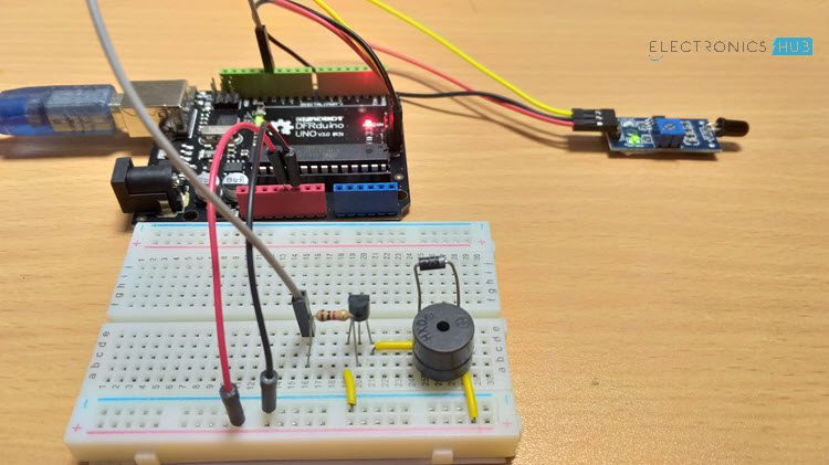
Arduino Flame Sensor Interface Image 1

NOTE: The Buzzer circuit is a safety measure and is not mandatory. You can connect the Buzzer directly to Arduino.

Code

The code of the Arduino Flame Sensor is very simple and is shown below.

Working

Make the necessary connections and upload the code to Arduino UNO. To test the functionality of the flame sensor, place a fired lighter or a match stick in front of the sensor.

Under normal conditions, the output from the Flame Sensor is HIGH. When the sensor detects any fire, its output becomes LOW.

Arduino detects this LOW signal on its input pin and activates the Buzzer.

NOTE: The on-board 10KΩ Potentiometer can be used to adjust the sensitivity of the sensor.

Applications

Flame Sensors are very important devices in detecting fire and they can be used in a variety of applications/areas like:

  • Car or Automobile
  • Fire Fighting Robots
  • Garage Safety Equipment
  • Warehouses

The post Arduino Flame Sensor Interface appeared first on Electronics Hub.

Friday, 6 July 2018

High-power thermoelectric generator utilizes thermal difference of only 5ºC

Researchers have designed and successfully developed a high-power, silicon-nanowire thermoelectric generator which, at a thermal difference of only 5ºC, could drive various IoT devices autonomously in the near future.

Ultra-thin sensor makes inflammation testing and curing 30 times faster

Researchers have developed a real-time ultraflexible sensor that makes inflammation testing and curing 30 times faster.

Thursday, 5 July 2018

Merging antenna and electronics boosts energy and spectrum efficiency

By integrating the design of antenna and electronics, researchers have boosted the energy and spectrum efficiency for a new class of millimeter wave transmitters, allowing improved modulation and reduced generation of waste heat. The result could be longer talk time and higher data rates in millimeter wave wireless communication devices for future 5G applications.

Heat-conducting crystals could help computer chips keep their cool

As consumers demand smaller, faster and more powerful electronic devices that draw more current and generate more heat, the issue of heat management is reaching a bottleneck. Researchers have created a potential solution -- boron arsenide crystals with high thermal conductivity, which might be used in future electronics to help keep devices from overheating.

Arduino Joystick Interface – Control Servo using Arduino and Joystick

In this project, I will show you how the Arduino Joystick Interface can be implemented and use the Arduino Joystick Interface in an application where I will control two Servo Motors and an LED.

I will discuss about the Analog Joystick Module, what a typical Joystick module consists of (i.e. its components), how the joystick module works and finally how to interface a Joystick with Arduino.

A Brief Note on Analog Joystick Module

You might have come across Joystick or Analog Stick as a Game Controller Device. A Joystick (sometimes also called as Thumb stick) is an input device and the Analog Stick is a type of Joystick which provides a 2-Dimensional Input.

NOTE: For the rest of the project discussion, only the term “Joystick” is used.

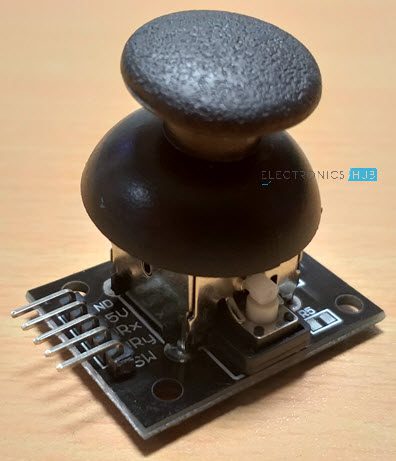
A typical Joystick module is shown in the following image.

Arduino Joystick Interface Joystick

An Analog Joystick usually consists of Potentiometers (two for each axis) and based on the position of these potentiometers, input is given (to a microcontroller, for example). A knob or a protrusion is used to change the position of the potentiometers.

Components of Joystick

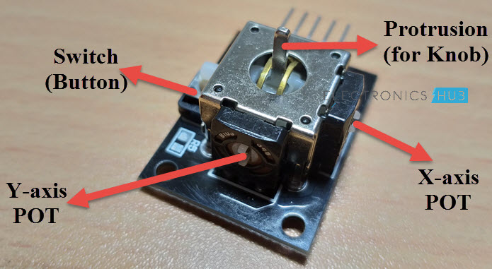
The following image shows the internal components of a typical Analog Joystick. There are two Potentiometers of 10KΩ each and additionally there is a switch which can be activated by pushing the knob down.

Arduino Joystick Interface Joystick Components

The following image shows the internal connections in a Joystick Module. As mentioned earlier, it consists of two 10KΩ Potentiometers, a push button (switch) and connectors (Pins). 

Arduino Joystick Interface Joystick Internal Circuit Pins of a Joystick

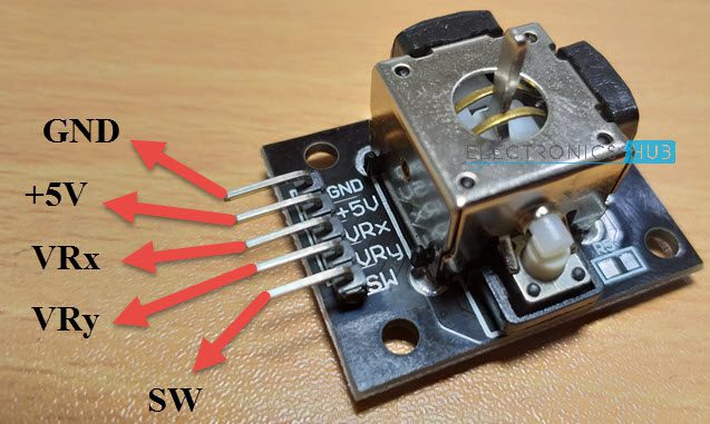
A typical Joystick Module consists of 5 Pin on its board. They are:

  • VRx
  • VRy
  • SW
  • +5V
  • GND

Here, +5V and GND pins must be connected to, well +5V and GND of a power supply (you can connect them to respective pins on Arduino). The VRx and VRy are the Wiper terminals of the two potentiometers.

Finally, SW is one end of a switch, where its other terminal is connected to GND (on the board of the Joystick).

The following image shows the pin diagram of the Joystick Module I am using. The orientation of the pins may vary depending on the manufacture but the pins will be the same.

Arduino Joystick Interface Joystick Pins

Arduino Joystick Interface

Now that you are familiar with the components and pins of a typical Joystick Module, let me take you through the Arduino Joystick Interface i.e. how to interface a Joystick with Arduino?

Arduino Joystick Interface Interfacing Joystick with Arduino

Since, the joystick is essentially a combination of two potentiometers (and a Switch, of course), you can easily guess how to interface it with Arduino as you might have already connected a potentiometer with Arduino.

Circuit Diagram

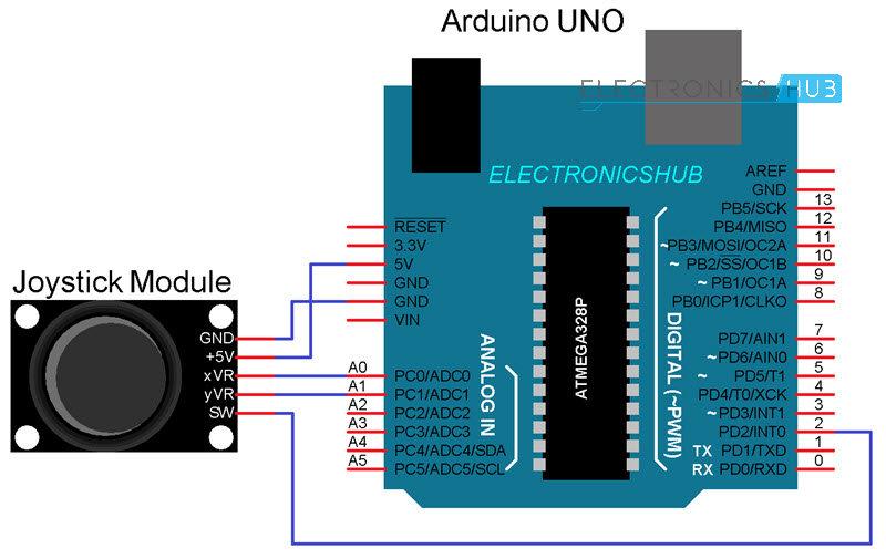
The following image shows a simple connection between Arduino UNO and the Joystick Module.

Arduino Joystick Interface Circuit Diagram

Code

Circuit Design and Working

I think the design of the circuit is very clear. Since the VRx and VRy pins are the wiper pins of the Potentiometers, they must be connected to the Analog Input pins of the Arduino UNO (as they give us analog voltages).

The switch pin on the other hand, is connected to Digital I/O Pin 2, with internal pull-up (implemented through code).

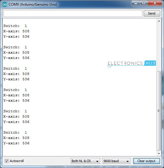
Coming to the working of the circuit, once the connections are made and the code is uploaded to Arduino, open the serial monitor. In that you can see the current values from both the potentiometers as well as the switch being updated on a regular basis (based on the delay).

Arduino Joystick Interface Serial Monitor

Since the input is Analog and we are converting it to Digital values, the output of the Joystick on both X-axis and Y-axis will be in the range of 0-1023.  

The next step in the Arduino Joystick Interface is to collect the values from the Joystick and use them to control a device, like an LED, motor or a servo.

Related post: ARDUINO SERVO MOTOR

How to Control Servo Motor with Arduino and Joystick?

There is no use in just interfacing a sensor with Arduino. You have to collect the data from the sensor and use to appropriately. In case of a Joystick Module, you get two potentiometers and a switch.

Which means, you get two different sources of Analog Inputs and one Digital Input. Using the Analog Inputs i.e. the X and Y movements of the Joystick, you can control different devices like a Servo Motor, for example and with the Digital Input (the Switch), you can control an LED i.e. turn it ON or OFF.

Circuit Diagram

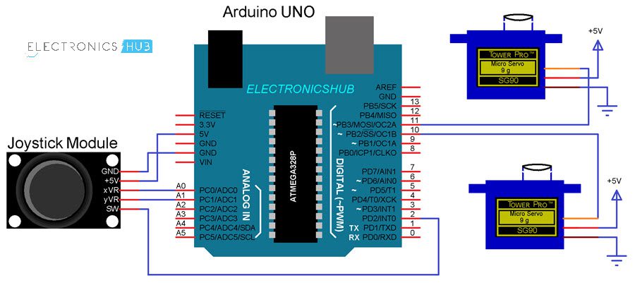
The following circuit diagram shows the necessary connections for controlling two Servo Motors using a Joystick and Arduino.

Arduino Joystick Interface Joystick Servos Circuit Diagram

Code

Circuit Design and Working

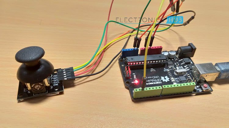
The connections with respect to the Joystick Module are the same i.e. +5V and GND to +5V and GND of Arduino, VRx and VRy to A0 and A1 (Analog Inputs 0 and 1) and the SW pin to Digital Pin 2.

Coming to the servo motors, their +V (Red) and GND (Brown) wires are connected to +5V and GND (preferably to another 5V Supply with common GND with Arduino). The control wires (Yellow or Orange) of the Servo Motors are connected to Digital I/O Pins 10 and 11.

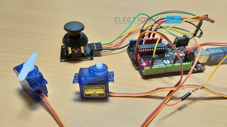
Once the code is uploaded to Arduino, it starts reading the data from the joystick and the default position of both the servos is initialized to 90 (in the range of 0-180).

Arduino Joystick Interface Joystick Servos

The idle values from the Joystick are 510 for X-Axis and 530 for Y-Axis in my case. Keeping these in reference, I have written the code such that, when the value from X-axis potentiometer falls below 300, the position of the X Servo is reduced by 5 from its current position and if the value from X-axis potentiometer becomes greater than 700, the position of the X Servo is increased by 5 from its current position.

A similar code is implemented even for the Y-Axis potentiometer and the Y Servo. Additionally, the switch of the Joystick is programmed to control the LED connected to Pin 13 of Arduino UNO.

Applications

Joystick can be used in various application like

  • Controlling DC Motors and Servo Motors 
  • Controlling LEDs 
  • Remote controlled Cars 
  • Robotic Control 

The post Arduino Joystick Interface – Control Servo using Arduino and Joystick appeared first on Electronics Hub.
Monday, 2 July 2018

Versatile ultrasound system could transform how doctors use medical imaging

A new ultrasound system that uses optical, instead of electronic components, could improve performance while giving doctors significantly more flexibility in how they use ultrasound to diagnose and treat medical problems.

Researchers develop recyclable, healable electronics

Electronics often get thrown away after use because recycling them requires extensive work for little payoff. Researchers have now found a w...