Wednesday, 11 August 2021
New electronic phenomenon discovered
Friday, 6 August 2021
New technology will allow important metals to be made more efficiently
Thursday, 5 August 2021
All in your head: Exploring human-body communications with binaural hearing aids
Brain-inspired highly scalable neuromorphic hardware
Mixing a cocktail of topology and magnetism for future electronics
Tuesday, 3 August 2021
Kick-starting supersonic waves in antiferromagnets
MOSFET Gate Resistor
Do you need a MOSFET gate resistor? What value should it be? And should it go before or after the pulldown resistor?
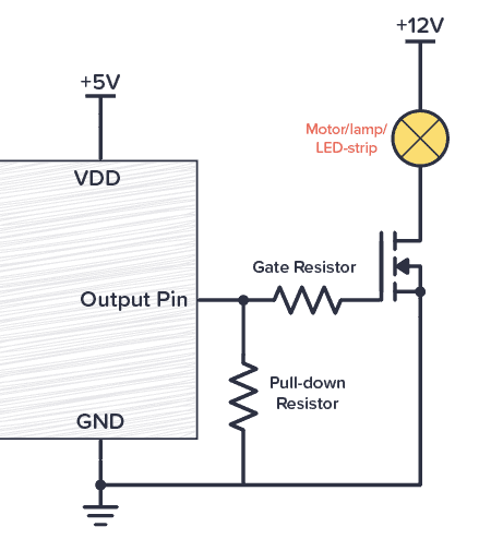
If you’re a bit impatient and just want the answer, here it is: You most likely need a gate resistor. And 1000 Ω will most likely work. See the circuit diagram below for connecting your MOSFET gate resistor (the Pull-down resistor is optional):
Why Do You Need a Gate Resistor?
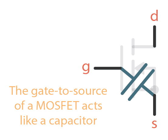
In how transistors work, we briefly touched upon that gate-to-source of a MOSFET acts as a capacitor.
And a capacitor works like this:
- When a capacitor is charging – current flows through it. A lot in the beginning, then less and less.
- When a capacitor is fully charged – no current flows through it.
When your MOSFET is turned on, its gate-source capacitor is fully charged. So there is no current flowing through the gate.
But when your MOSFET is being turned on, you’ll have a current that is charging this gate-source capacitor. So for a small fraction of a second, there can be a lot of current flowing.
To make sure this short burst of current isn’t too high for your Arduino/Raspberry Pi/microcontroller (or whatever you’ve connected it to) you need to add a resistor in series between the output pin and the MOSFET transistor’s gate:
Choosing A Resistor Value
Often 1000 Ω is a good enough value for this. But it depends on your circuit.
You can calculate the maximum current you get from a resistor by using Ohm’s law for current:

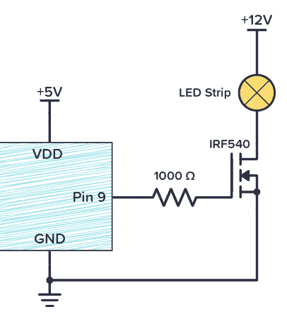
For example in the case of Arduino that has 5V on its output pins, 1000 Ω gives you a maximum current of 5 mA (and Arduino pins can handle up to 40 mA):

Keep in mind that the higher resistance you are using, the slower the MOSFET will turn on.
MOSFET Gate Resistor Placement
Are you using a pulldown resistor for your MOSFET? Then remember that if the gate resistor is placed to the left of the pulldown resistor, you get a voltage divider circuit that will reduce the voltage to the gate:
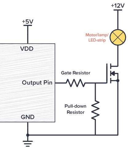
If you have chosen a gate resistor that is at least 100 times smaller than the pulldown resistor, then the reduction in voltage is so small that it doesn’t matter. But if they are a bit closer in value, the voltage on your gate will be lower than the pin voltage.
The solution? Switch places between the two so that the pulldown resistor is connected directly to the output pin:
Copyright Build Electronic Circuits
-
Do you need a MOSFET gate resistor? What value should it be? And should it go before or after the pulldown resistor? If you’re a bit impati...
-
In this project, we will learn about the MCP2515 CAN Controller Module, how to interface the MCP2515 CAN Bus Controller with Arduino and fin...
-
Do you want to learn electronics, so that you can build your own gadgets? There is a ton of resources on learning electronics – so where...


