In this DIY Project, I will show you how to design a simple Arduino based Door Monitoring system using Reed Switch.
A Door Monitoring System is a simple application which continuously monitors the status of the Door i.e. whether it is opened or closed. Based on the status further actions like making an alarm, sending a message, calling a number etc. can be implemented.
Even though this Arduino based Door Monitoring System seems a simple project, it need not necessarily be implemented as a standalone application. This Door Monitoring System can be integrated into a home security system or burglar alarm system (or something similar) and can act as an additional safety feature.

Project Overview
If you remember the previous project, I have shown you How a Reed Switch Works and How to Connect a Reed Switch with Arduino. This project can be considered as an extension to that project.
In the previous Reed Switch Project, I have controlled an LED i.e. turned it ON and OFF based on the state of the Reed Switch i.e. switch is closed (when the magnet is near) or open (when the magnet is away).
Taking the same principle, I have implemented a simple Arduino based Door Monitoring System using Reed Switch where based on the state of the switch, I will determine whether the door is open or close.
Circuit Diagram of Arduino based Door Monitoring System
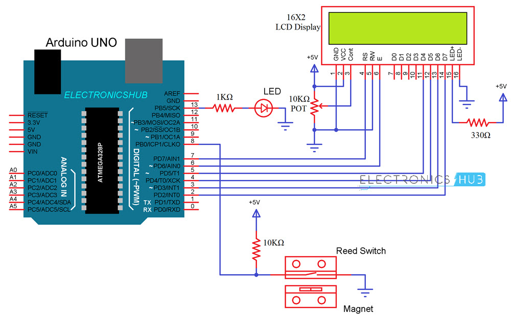
The circuit diagram of the Arduino based Door Monitoring System using Reed Switch is shown in the image below.

Components Required
- Arduino UNO (or any Arduino Board)
- Reed Switch with Magnet (preferably like the one used in this project)
- 16 x 2 LCD Display
- 10 KΩ Resistor
- 1 KΩ Resistor
- 330 Ω Resistor (for LCD Backlight – optional)
- LED
- Mini Breadboard
- Connecting Wires
- Power Supply
- USB Cable for Arduino (to program)
Circuit Design
The design of the circuit for Arduino based Door Monitoring System is very simple. First, the 16 x 2 LCD. The data pins D4, D5, D6 and D7 of the 16 x 2 LCD Module are connected to Digital IO Pins 5, 4, 3 and 2 of Arduino UNO respectively.
The LCD Control Pins RS, RW and E are connected to Pin 7, GND and Pin 6 of Arduino respectively. The backlight LED pins (Pins 15 and 16) are connected to +5V and GND (a 330Ω Resistor can be used as a current limiter).

Pins 1 and 2 of the 16 x 2 LCD are connected to GND and +5V. Pin 3 is connected to the centre (wiper) terminal of a 10KΩ Potentiometer while the other two ends of the POT are connected to +5V and GND.
Coming to the Reed Switch, one end of the Reed Switch is connected to GND and the other end connected to Pin 8 of Arduino. Also, the Pin 8 of Arduino is pulled-HIGH with the help of a 10KΩ Resistor.
An LED is connected to Pin 13 of the Arduino (on-board LED is used) and it is used as an indicator.
Code
The Arduino Code for the Door Monitoring System is given below.
How to Setup Arduino based Door Monitoring System Project?
Since the Reed Switch is the main component in determining the status of the door, setup will be based on the position of the Reed Switch.
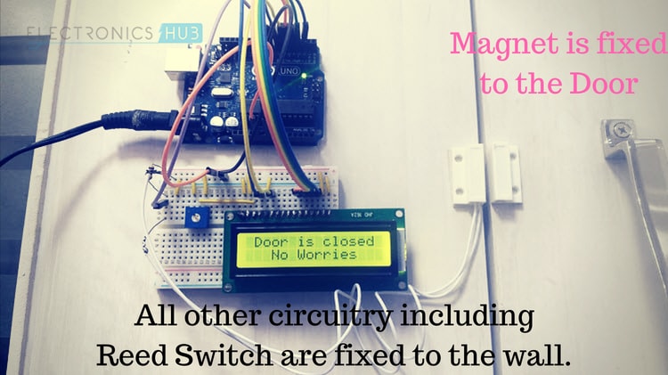
By now, you know that Reed Switch consists of two parts: The actual Reed Switch and a Magnet. In my setup, I have fixed the Magnet to the edge of the door.

Directly in front of the magnet, I have fixed the Reed Switch on the wall (or the non-moving part near the wall). The maximum detecting distance between the Reed Switch and the Magnet is around 1.5cm in my case i.e. anything more that this, the Reed Switch will not detect the magnet.
The Arduino and the other components are placed near the Reed Switch so that they will be firmly fixed to the wall. The only thing that will be moving is the Magnet that is fixed to the door.
Working
If you followed the earlier project How to Connect a Reed Switch with Arduino, then understanding the working of this project won’t be that hard.
Since closed door is the ideal position, the Magnet and the Reed Switch will always be near and the Reed Switch will be in closed state (since my Reed Switch is a Normally Open type).

When the door is opened, the magnet moves away from the Reed Switch along with the door and the switch moves back to Open state.
As Arduino continuously monitors the state of the pin to which the Reed Switch is connected, a change in state will trigger the Arduino and a warning message is displayed on the LCD (along with the LED being lit up).

Applications
- As mentioned in the introduction, this Arduino based Door Monitoring System can be used to monitor doors when it is locked for a long time (usually, when you are on a trip or out of town).
- Instead of displaying the status, you can modify the circuit to make a call to a registered mobile number by integrating a GSM Module.
- You can combine this system with other security measures like Burglar Alarm, Laser Security System etc. and build a complex Home Security System yourself.
The post Arduino based Door Monitoring System using Reed Switch appeared first on Electronics Hub.
No comments:
Post a Comment