Introduction
In this project, I will show you how to interface a Water Flow Sensor with Arduino. Using this Arduino Water Flow Sensor tutorial as a reference, you can implement a system which can measure the quantity of water (or any liquid) flowing through a pipe.
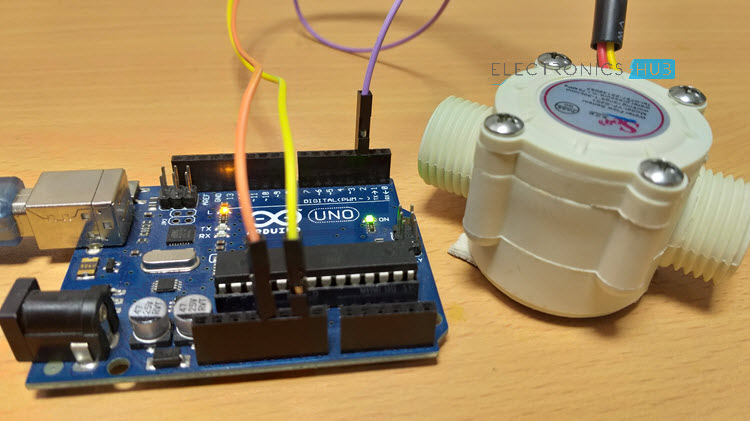
Monitoring Liquid Flow is very important in a variety of application like a simple plant watering system in your home garden to complex pharmaceutical and food processing industries.
Water Flow Sensors are simple devices which can aid us in measuring the flow of a liquid. In this project, I will talk a little bit Water Flow Sensors, how a water flow sensor works and how to interface a simple water flow sensor with Arduino.
A Brief Note on Water Flow Sensor
Water Flow Sensor, as the name suggests, is a device to measure the flow of water. The Water Flow Sensor used in this project is shown in the image below.
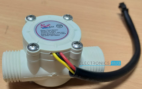
It has a plastic valve body with a rotor and a hall sensor circuit. It has three wires namely +5V (Red), GND (Black) and Output (Yellow). Since it works on +5V, it can be interfaced with any microcontroller like Arduino, for example.
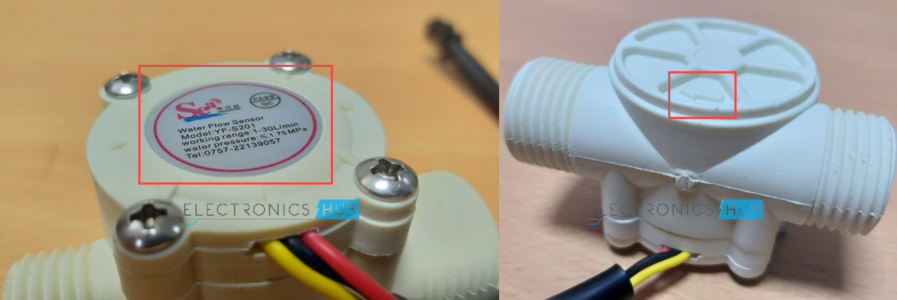
If you notice the water level sensor, there is some information on the top and bottom of the sensor. On top, there is a label with vital information about the sensor.
The information on the label is as follows:
- Model: YF-S201
- Working Range: 1 – 30 L/min
- Water Pressure: ≤ 1.75 MPa
On the bottom of the sensor, there is a marking in the form of an arrow, to indicate the required direction of flow of water through the sensor. So, it is important that when connecting this sensor to a pipe, make sure that you follow this direction.
How Water Flow Sensor Works?
The Water Flow Sensor is implemented using a Hall effect Sensor. So, the working of the Water Flow Sensor can be easily understood if you are familiar with a Hall Effect Sensor.
Basically, the YF-S201 Water Flow Sensor consists of a Flap Wheel (or a Turbine Wheel) that spins when water flows through the sensor. At the centre of this flap wheel, there is magnet fixed.
Now coming to the Hall Effect Sensor part, the Hall Effect Sensor used in my Water Flow Sensor is Honeywell’s 460S Hall-effect Sensor IC. It is a TO-92 Packaged IC.
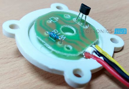
Based on the data sheet provided by Honeywell, the working of 460S Hall-effect sensor is as follows: when the South Pole of the magnet is towards the IC, then the output of the sensor is LOW and when the North Pole of the magnet is towards the IC, then the output is HIGH.
Keeping this in mind, when the water flows through the YF-S201 Water Flow Sensor, the flap wheel spins due to the force of the water and as a result, the magnet attached to it will also spin.
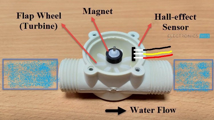
As a result, the magnetic field near the Hall-effect sensor switches polarity as the flap wheel spins and the output of the sensor (on the output Pin – Yellow Wire) will be a pulse.
By keeping track of the number of pulses from the output of the Water Flow Sensor, you can easily calculate the amount of water flowing through the sensor and as a result the Water Flow Rate.
Circuit Diagram of Arduino Water Flow Sensor Interface
The circuit diagram for Arduino Water Flow Sensor Interface is shown in the image below.
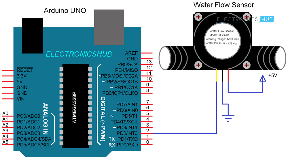
NOTE: Internally, the Output Pin of the Hall Effect Sensor is pulled HIGH on the circuit board itself (as you can see in the breakdown image show above). Hence, I have not used any external pull-up resistors.
Components Required
- Arduino UNO
- YF-S201 Water Flow Sensor
- Connecting Wires
Circuit Design
Connect the Red and Black wires of the YF-S201 Water Flow Sensor to +5V and GND. Since I will be using the Interrupt feature of the Arduino, only Digital I/O Pins 2 and 3 are possible to connect to the Output of the Water Flow Sensor.
In this project, I have connected the Output of the Water Flow Sensor (Yellow Wire) to Digital I/O Pin 2 of Arduino UNO.
Code
The code for the Arduino Water Flow Sensor Interface is given below. There is a small calculation in the code, which I will explain in the further sections.
Calculations
The output of the project is to display the quantity of water flowing through the sensor in litres per hour as shown below. In order to obtain this, there is a small calculation.
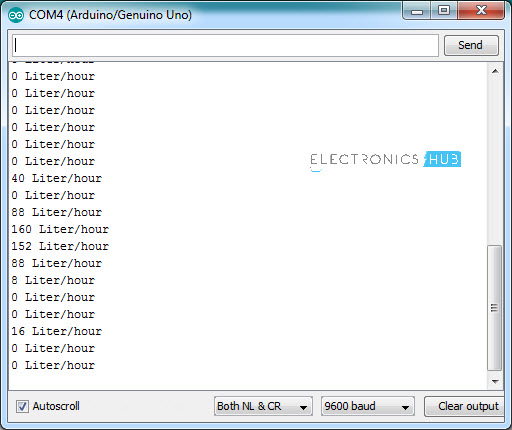
Referring to the data sheet of the YF-S201 Water Flow Sensor, since the output of the sensor is a pulse, by calculating the frequency of the pulse, we can calculate the volume of the water flowing through the sensor.
The pulse frequency in Hz is 7.5 * Flow Rate (in Litres per minute). So, the quantity of water in Litres per Hour is Pulse Frequency * 60 / 7.5.
The post Arduino Water Flow Sensor Interface – Hookup Guide & Tutorial appeared first on Electronics Hub.
No comments:
Post a Comment