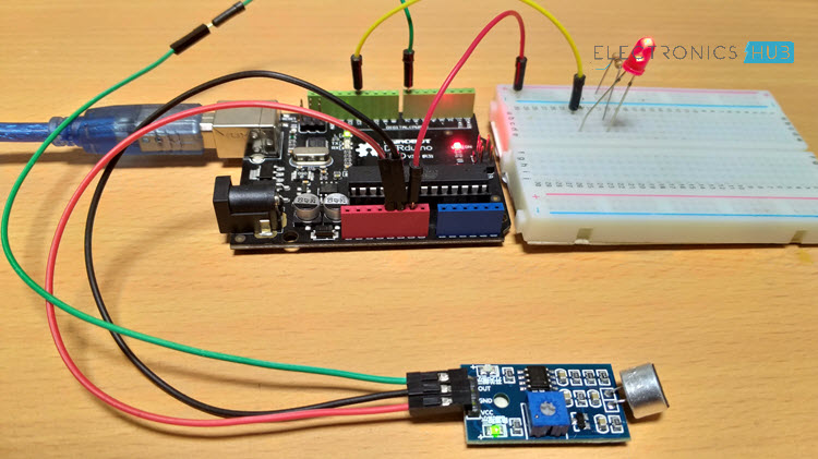
In this project, we will learn about a new Sensor called Sound Sensor or Sound Detector. Also, I will show you how to interface a Sound Sensor with Arduino and implement a Relay control project using Arduino, Sound Sensor and a Relay Module.
Introduction
I have already implemented a sound related project a while ago which is called as HOW TO MAKE A SIMPLE CLAP SWITCH. That project is based on the famous 555 Timer IC.
In this project, I will be using a different Sound Sensor (although the idea is the same), which is sensitive to sounds like loud voices, claps, snaps, thuds and taps.
We live in a World of virtual assistants with voice interactions and they even make your haircut appointments!
Implementing a sound sensor in our DIY project today may seem a little outdated but I feel that learning something new and building a project on our own is better than buying a speaker and talking with it (pun intended).
A Brief on Sound Sensor (Sound Detector)
A Sound Sensor is a simple device that detects sound. It is simply put a Microphone with some processing circuit. Using a Sound Sensor, you can measure the intensity of sound from different sources like knocks, claps, loud voices, etc.
The Sound Sensor used in this project is shown in the image below.
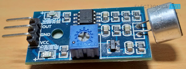
It consists of a microphone, a voltage comparator IC (LM393), a potentiometer, a transistor, couple of LEDS and a few other passive components (resistors and capacitors).
Pins and Components of Sound Sensor
- Microphone
- LM393 Voltage Comparator IC
- NPN Transistor (marked as J6 on my board)
- 10KΩ Resistors x 2
- 1KΩ Resistors x 3
- 10KΩ Potentiometer
- 100nF Capacitors x 4
- LEDs x 2
- 510KΩ Resistor
- 51KΩ Resistor
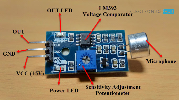
The following image will help you identify the components and pins on a typical LM393 IC based Sound Sensor Module.
Schematic of Sound Sensor
If you want to understand a little bit more about the sound sensor module, then knowing the schematic is the best way to get started. There are several Sound Sensor Modules available in the market that are implemented using different ICs like LM324, LM393, LM344, LM386 etc. So, check your sound sensor for the main IC and determine its schematic.
The following image shows the schematic of the Sound Sensor Module that is implemented using LM393 Voltage Comparator IC.
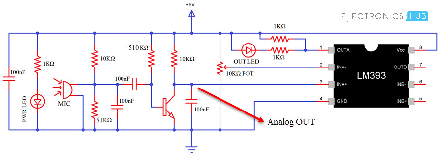
If you observe in the Schematic, I have pointed out where you can extract the Analog Output from the sensor. In most LM393 based Sound Sensors, only Digital Out is available i.e. when detected sound is Higher or Lower than a certain level, the output of the sensor will Low or High.
In my case, the sound sensor will produce a logic LOW when sound is detected and a logic HIGH when there is no sound.
Interfacing Sound Sensor with Arduino
As the project is about interfacing a Sound Sensor with Arduino, let us see how its done. For this, I have designed a couple of circuit where in the first circuit I will just interface the Sound Sensor with Arduino and detect the sound with the help of an LED.
Coming to the second circuit, I will control a relay with the help of sound (snap of fingers). For both the sensors, the part with interfacing of the Sound Sensor with Arduino is same but the actions after detecting the sound is different.
Also, since I have already mentioned that my sound sensor has only digital output, I will be using only the digital I/O pins of the Arduino.
Components Required
- Sound Sensor Module
- Arduino UNO
- Relay Module (5V)
- LED
- 1KΩ Resistor
- Connecting wires
- Mini Breadboard
Circuit Diagram of Interfacing Sound Sensor with Arduino
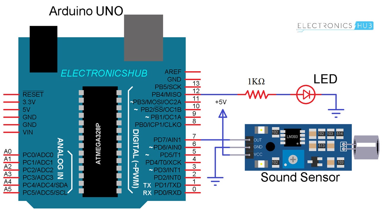
Circuit Design
Connect VCC and GND of the sound sensor to +5V and GND of Arduino. Connect the OUT pin of the Sensor to Digital I/O pin 7 of Arduino UNO. Finally, connect an LED with 1KΩ resistor to Pin 12 of Arduino.
Code
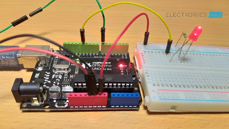
Working
After making the connections and uploading the code to Arduino, snap or clap in front of the sensor. You can observe the LED connected to OUT Pin of the sound sensor as well as the Digital Pin 12 of Arduino will be active whenever it detects any sound.
Control a Relay with Sound Sensor and Arduino
Coming to the applications of sound sensor, the following is a simple circuit using Arduino, Sound Sensor and Relay module.
Circuit Diagram
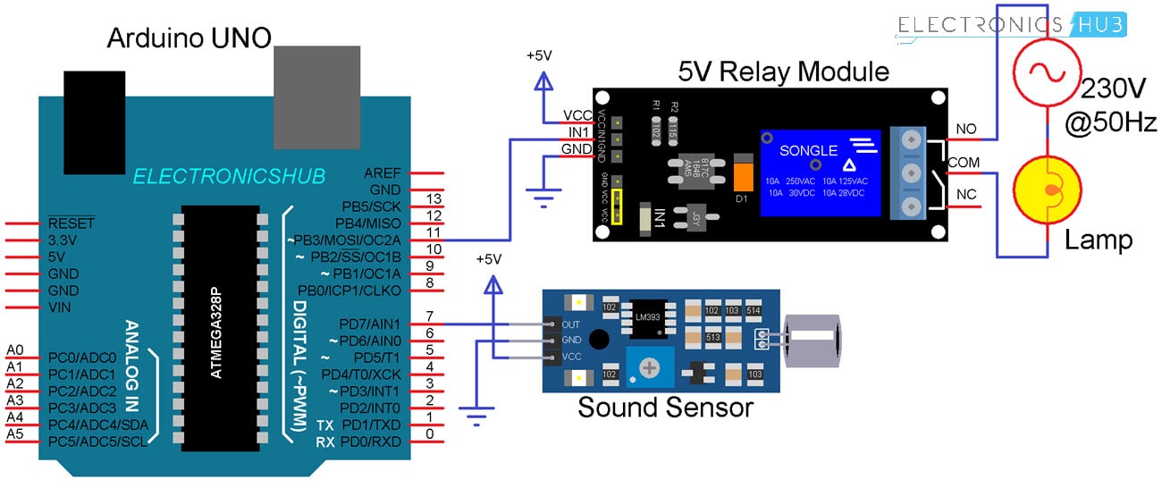
Circuit Design
The only difference between the earlier circuit and this circuit is that the LED is removed and a relay module is connected to digital I/O pin 11 of Arduino.
NOTE: I have not connected any load to the relay as this is just a demonstration.
Warning: If you intend to you your relay to actually control an electrical device, be extremely careful when making the AC Mains connections.
Code
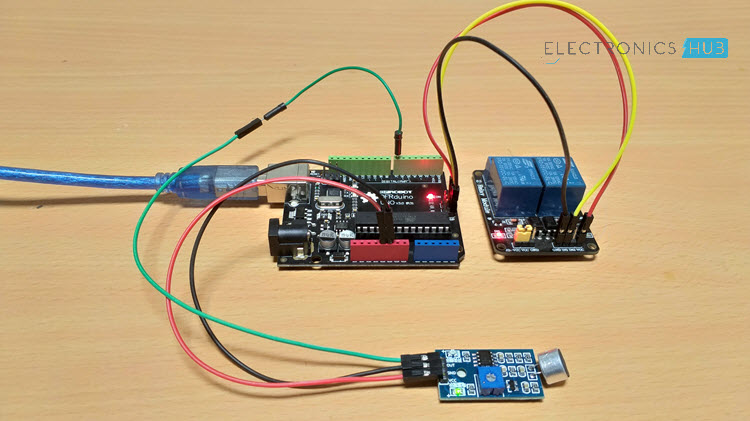
Working
Even though the implementation of the Relay control is similar to that of an LED, the internal execution is a little bit different.
After making the connections and uploading the code, make a sound like snap or clap in front of the sensor to turn ON the relay.
Make the sound once again to turn OFF the relay.
Applications
Sound Sensor can be used in various applications like:
- Security Systems
- Burglar Alarms
- Device Control
- Door Alarms
The post Interfacing Sound Sensor with Arduino – Add Sound Detection to Arduino appeared first on Electronics Hub.
No comments:
Post a Comment