What is an Electric Circuit?
An Electric Circuit is a closed path for transmitting an electric current through the medium of electrical and magnetic fields. The flow of electrons across the loop constitutes the electric current. Electrons enter the circuit through the ‘Source’ which can be a battery or a generator. The source provides energy to the electrons, by setting up an electrical field which provides the electromotive force.
The electrons leave the circuit through the load, to the earth ground, thus completing a closed path. The load or output can be any simple home appliance like television, lamp, refrigerator, or can be a complex load such as that on a hydroelectric power generating station.
A simple electric circuit consists of a source (such as a battery), wires as conducting medium and a load (such as a light bulb). The battery provides required energy for flow of electrons, to the light bulb.
Basic Circuit Elements
As mentioned above in the introduction, a circuit is an interconnection of elements. These elements are classified into active or passive elements, based on their capability to generate energy.
Active Circuit Elements
Active Elements are those which can generate energy. Examples include batteries, generators, operational amplifiers and diodes. Note that in an electrical circuit, the source elements are the most significant active elements.
An energy source, whether a voltage or current source, is of 2 types – Independent and Dependent sources. Example of an Independent source is the battery which provides a constant voltage to the circuit, irrespective of the current flowing through the terminals.
Example of a dependent source is a transistor, which provides current to the circuit, depending upon the voltage applied to it. Another example is an Operational Amplifier, which provides voltage, depending upon the differential input voltage applied to its terminals.
Passive circuit Elements
Passive Elements can be defined as elements which can control the flow of electrons through them.They either increase or decrease the voltage. Here are some examples of passive elements.
Resistor: A resistor opposes the flow of current through it. For a linear circuit, Ohm’s law is applicable, which states that voltage across the resistor is directly proportional to the current flowing through it, the proportional constant being the resistance.
Inductor: An inductor stores energy in form of the electromagnetic field. The voltage across an inductor is proportional to the rate of change of current flowing through it.
Capacitor: A capacitor stores energy in form of the electrostatic field. The voltage across a capacitor is proportional to the charge.
Types of Electrical Circuits
DC Circuits
In DC Circuits, the excitation applied is a constant source. Based on the type of connection of active and passive components with the source, a circuit can be classified into Series and Parallel circuits.
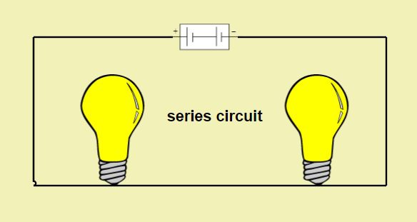
Series Circuits
When several passive elements are connected in series with an energy source, such a circuit is known as a series circuit. For a series circuit, same amount of current flows through each element and voltage is divided. In series circuit, as the elements are connected in a line,if there is faulty element among them ,complete circuit acts as open circuit.
- For a resistor connected in DC circuits, the voltage across its terminals is directly proportional to the current passing through it, thus maintaining a linear relationship between the voltage and current. For resistors connected in series, the total resistance is equal to the sum of all resistance values.
- For capacitors connected in series, the total capacitance is equal to the sum of reciprocals of all capacitance values.
- For inductors connected in series, total inductance is equal to the sum of all inductance values.
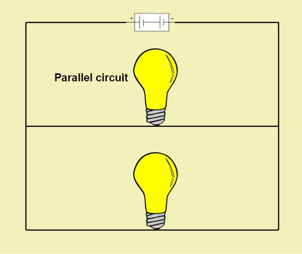
Parallel Circuits
In a parallel circuit, one terminal of all the elements is connected to the one terminal of the source and the other terminal of all elements is connected to the other terminal of the source.
In parallel circuits, the voltage remains the same in the parallel elements while the current changes. If there is any faulty element among parallel elements there is no effect on the circuit.
- For resistors connected in parallel, the total resistance is equal to the sum of reciprocals of all resistance values.
- For capacitors connected in series, the total capacitance is equal to the sum of all capacitance values.
- For inductors connected in series, total inductance is equal to the sum of all reciprocals of inductance values.
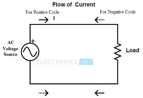
AC circuits
Ac circuits are those circuits, Whose excitation element is an AC source. Unlike DC source which is constant AC source has variable current and voltage at regular intervals of time. Generally, for high power applications, AC circuits are used.
Simple AC Circuit using resistance
For alternating current passing through the resistor, the ratio of current and voltage depends upon the phase and frequency of the supply. The applied voltage will change constantly with time and Ohm’s law can be used to calculate current passing through the resistor at any instant of time.
In other words, if at time t seconds, the value of voltage is v volts, current will be:
i = v/R
where the value of R is always constant.
Above equation shows that polarity of current depends upon that of the voltage. Also, both current and voltage reach their maximum and zero points at the same time. Thus, for a resistor, voltage is in phase with the applied current.
Consider the below circuit diagram
When the switch is closed, current passes through the resistor and is given by the below equation
i=Im cos(ωt+Φ)
Voltage,V=IR=RIm cos(ωt+Φ)
For a resistor, both voltage and current values will rise and fall at the same time. Hence, the phase difference between voltage and current is zero.
AC Circuit using pure inductance
A coil of thin wire wrapped on a cylindrical core is known as an Inductor. The core can be an air core (hollow laminated) or an iron core. As alternating current flows through the inductor, the magnetic field also changes. This change in magnetic field results in an induced voltage across the inductor. As per Lenz law, the induced voltage is such that it opposes the flow of current through it.
During the first half cycle of the source voltage, the inductor stores energy in form of magnetic field and in the next half, it releases energy.
The induced EMF is given as below
e=Ldi/dt
Here, L is the self-inductance.
Now, Input AC voltage applied is given as v(t)=Vm Sinωt
Current through the inductor is:I(t)=Im Sinωt
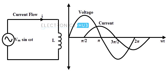
So, the voltage across the inductor would be
e=L di/dt=wLI_m coswt=wLI_m sin(wt+90)
Thus, for an inductor, voltage leads the current by 90 degrees.
Now, resistance by an inductor is termed as Reactance and given by
Thus, impedance or resistance is proportional to rate of change of current for an inductor.
AC Circuit with a capacitor
For a constant DC supply, the capacitor plates charge up to the applied voltage, stores this charge temporarily and then starts discharging. Once a capacitor is fully charged, it blocks the flow of current as the plates get saturated.
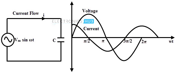
When AC supply voltage is applied to a capacitor, the rate of charging and discharging depends upon the supply frequency. Voltage across the capacitor lags the current flowing through it by 90 degrees.
Current through the capacitor is given as
e = Ldi/dt
The capacitive reactance is given as:
e = Ld/idt
Thus, impedance or reactance to AC supply is inversely proportional to the frequency of supply.
What is a short circuit and an open circuit?
Short Circuit
A low or negligible resistance connection between two conductors in an electric circuit is termed as a short circuit. A short circuit would result in the production of more heat and eventually resulting in sparks, flames or smoke.
A short circuit can be caused due to loose connections, faulty insulation, abrupt chewing up of wires by pests, and old appliances. One of the best and commonly used techniques to prevent damages using short circuit is using a fuse or a circuit breaker.
Open Circuit
An open circuit is caused due to an interruption in the electrical circuit. When any element in a circuit is left unconnected, an open circuit is created. While voltage across an open circuit has some finite value, current is zero.
Circuit Protection
Deliberate installation of a weak link within an electrical circuit is known as circuit protection. Purpose behind this installation is the prevention of damage due to short circuit, excess amount of temperature and other damages.
A circuit protection device can be a fuse, circuit breaker, a thyristor or a switch.
The post Basic Electrical Circuits-Components,Types appeared first on Electronics Hub.


No comments:
Post a Comment