Thursday, 31 January 2019
Layered 2D materials: Maximizing the potential of MXenes
Hybrid electricity system would reduce rates, improve service
Computational algorithm to reduce electromagnetic noise in electronic circuits developed
Wednesday, 30 January 2019
Waterproof graphene electronic circuits
Tuesday, 29 January 2019
Electrical conductivity in doped organic semiconductors
Graphene: Large, stable pieces of graphene produced with unique edge pattern
New quantum system could help design better spintronics
Better batteries: The energy implications of organic radical polymers
Monday, 28 January 2019
Converting Wi-Fi signals to electricity with new 2D materials
Sunday, 27 January 2019
Innovative technique could pave way for new generation of flexible electronic components
Unlocking graphene's superconducting powers with a twist and a squeeze
Saturday, 26 January 2019
'GO dough' makes graphene easy to shape and mold
Friday, 25 January 2019
Static electricity could charge our electronics
Engineers develop novel strategy for designing tiny semiconductor particles for wide-ranging applications
Wednesday, 23 January 2019
New 3D nanoprinting strategy opens door to revolution in medicine, robotics
Materials chemists tap body heat to power 'smart garments'
Tuesday, 22 January 2019
Promising steps towards large scale production of graphene nanoribbons for electronics
Monday, 21 January 2019
Mechanical engineers develop process to 3-D print piezoelectric materials
Friday, 18 January 2019
Smart microrobots that can adapt to their surroundings
Thursday, 17 January 2019
New light shed on intensely studied material
Wednesday, 16 January 2019
Monday, 14 January 2019
Breakthrough in organic electronics
Scientists develop promising new type of polymers
5000 times faster than a computer
Next generation photonic memory devices are light-written, ultrafast and energy efficient
Saturday, 12 January 2019
Friday, 11 January 2019
Thursday, 10 January 2019
Spintronics 'miracle material' put to the test
Saving energy by taking a close look inside transistors
Wednesday, 9 January 2019
New technique offers rapid assessment of radiation exposure
Tuesday, 8 January 2019
Nanophysicists developed a high-performance organic phototransistor
Friday, 4 January 2019
Excitons pave the way to more efficient electronics
Wednesday, 2 January 2019
Interfacing Soil Moisture Sensor with Arduino
In this project, I will talk about Soil Moisture Sensor and how can we save water in our home gardens by Interfacing Soil Moisture Sensor with Arduino and controlling the water supply to plants.
Introduction
If you have a home garden or a backyard with turf, then you might probably know how much we need to take with watering the plants and turf.
Garden Sprinklers are one of the frequently used options for watering the lawn and for plants, well, the only option and the best one is manual watering.
But if you are planning to make an Automatic Plant Watering system, where the water supply either through sprinklers or drip irrigation system, then you have to consider the amount of Soil Moisture.
By measuring the Soil Moisture in the garden, you can precisely control the amount of water to be supplied with the help of a simple mechanism involving a Water Pump and a Microcontroller.
In this project, I will show you how to monitor the soil moisture of a small pot by Interfacing Soil Moisture with Arduino
A Brief Note on Soil Moisture Sensor
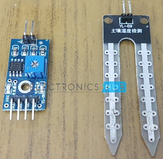
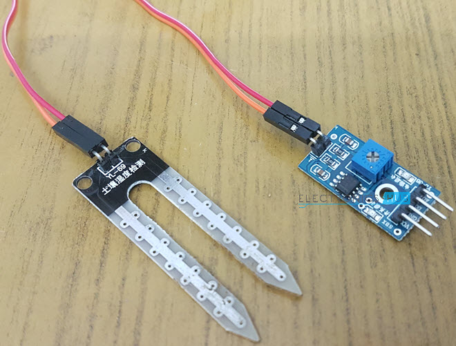
The main component of the project (apart from the Arduino UNO) is the Soil Moisture Sensor. It consists of two parts: The main Sensor and the Control Board.
Sensor part of the Soil Moisture Sensor consists of a couple of conductive probes that can be used to measure the volumetric content of water in soil.
Coming to the control board, it is made up of LM393 IC, which is a voltage comparator. The board also consists of all the necessary components like connectors, LEDs, resistors etc. to measure the Soil Moisture.
Additionally, there is an option to adjust the sensitivity of the module with the help of a Potentiometer.
Working of Soil Moisture Sensor
The working of the Soil Moisture Sensor is very simple. It works on the principle of voltage comparison. The following circuit will be helpful in understanding the working of a typical soil moisture sensor.
As you can see, one input of the comparator is connected to a 10KΩ Potentiometer while the other input is connected to a voltage divider network formed by a 10KΩ Resistor and the Soil Moisture Probe.
Based on the amount of water in the soil, the conductivity in the probe varies. If the water content is less, the conductivity through the probe is also less and hence the input to the comparator will be high. This means that the output of the comparator is HIGH and as a result, the LED will be OFF.
Similarly, when there is adequate water, the conductivity of the probe increases and the output of the comparator becomes LOW. The LED then starts glowing.
Interfacing Soil Moisture Sensor with Arduino
Now that we have seen how a typical soil moisture sensor works, let me take you through the steps of Interfacing Soil Moisture with Arduino. The main advantage of this soil moisture module is that you can get the analog output from it. By using this analog signal and giving it to the Analog IN of Arduino, you can precisely calculate the percentage of moisture in the soil.
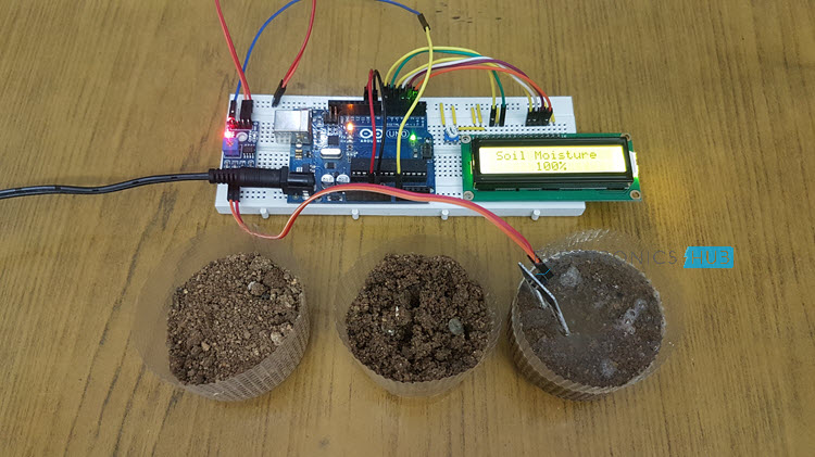
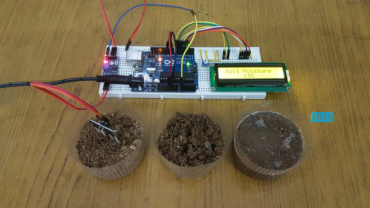
Coming to the setup for testing the project, I have used to plastic cups filled with soil from my garden. The amount of water in each cup is more than the previous one.
Circuit Diagram
Components Required
- Arduino UNO
- Soil Moisture Sensor Module
- 16×2 LCD Display
- 10KΩ Potentiometer (for LCD)
- Breadboard
- Connecting wires
- Power Supply
- Test setup with 3 cups of soil
Circuit Design
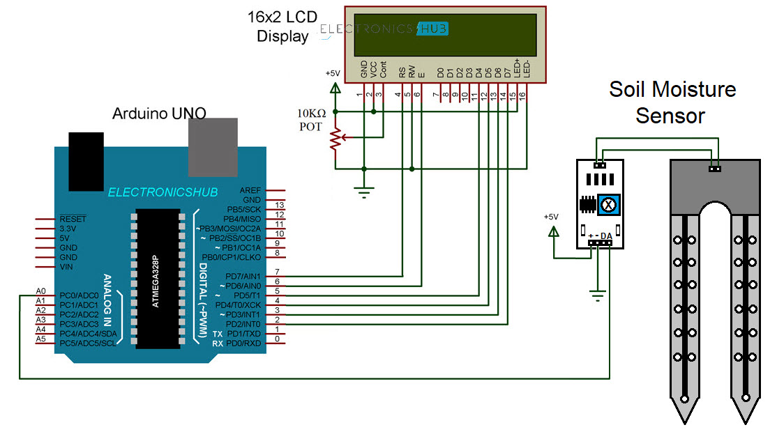
The design of the circuit is very simple. Connect the probe to the board and provide power supply to the board. Take the analog out pin from the board and connect it to Analog IN pinA0 of the Arduino.
To view the results, I have used a 16×2 LCD Display, where I have connected its data pins D4 – D7 to Arduino Pins 5 – 2. All the additional connections are mentioned in the circuit diagram.
Code
How to Measure Soil Moisture with Arduino?
- Make the connections asper the circuit diagram and upload the code to Arduino.
- Place the soil moisture probe in a “dry” pot and check for readings. In my case, it was around 13%.
- Similarly, place the probe in other pots (after properly cleaning the probe) and check for readings.
- You can adjust the sensitivity of the sensor with the help of the potentiometer on the board of the sensor.
Applications
You can use soil moisture sensor in
- Home Gardens
- Lawns
- Interior Plants
- Office and low light plant setup
The post Interfacing Soil Moisture Sensor with Arduino appeared first on Electronics Hub.
Arduino Car Speed Detector
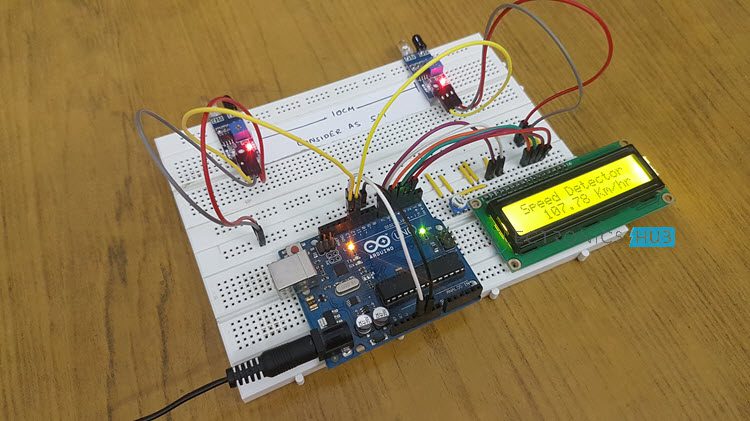
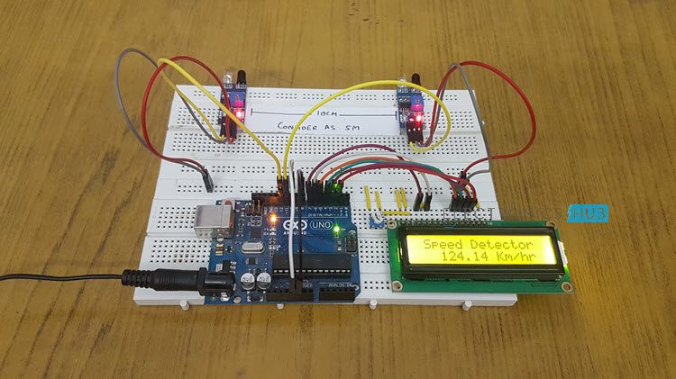
In this project, I will show you how to design and build a simple Car Speed Detector circuit using Arduino UNO and IR Sensors. This Arduino Car Speed Detector project can be used to detect speed of a moving car.
Introduction
There are definite rules laid out by authorities about driving cars on roads. The most common rule in any country is speed limit in certain roads i.e. you will be in violation of the law if your car speed exceeds this limit.
In order to detect the speed of a moving car, the patrolling officers usually depend on a handheld gun that works on Radar Technology or Lidar Technology. This is a tedious process as the officer has to manually check for over speeding for each vehicle.
What if the Car Speed Detection is made automatic? A simple automatic detection of speed of a vehicle is designed in Arduino Car Speed Detector project, where you can place the system in one place and view the results instantly without any human intervention.
Principle of the Project
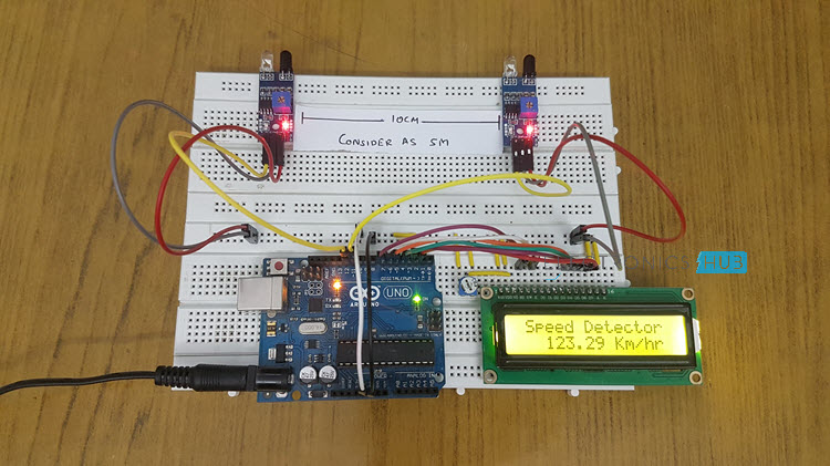
IR Sensors are the main part of the project that detect the speed of a car. Practically, you can implement the setup of IR Sensors in many ways but in this project, I have used two reflective type IR Sensors and placed them 10cm apart.
When a car travelling reaches the first sensor, the IR Sensor gets activated. From this moment onward, a timer is initiated and will continue to keep time until the car reaches the second IR Sensor.
By simulating the distance between the two sensors to be 5 meters, you can calculate the speed at which the car travelled from IR Sensor 1 to IR Sensor 2 as you already know the time of travel.
All the calculations and data gathering are done by Arduino and the final result is displayed on a 16X2 LCD Module.
Circuit Diagram of Arduino Car Speed Detector
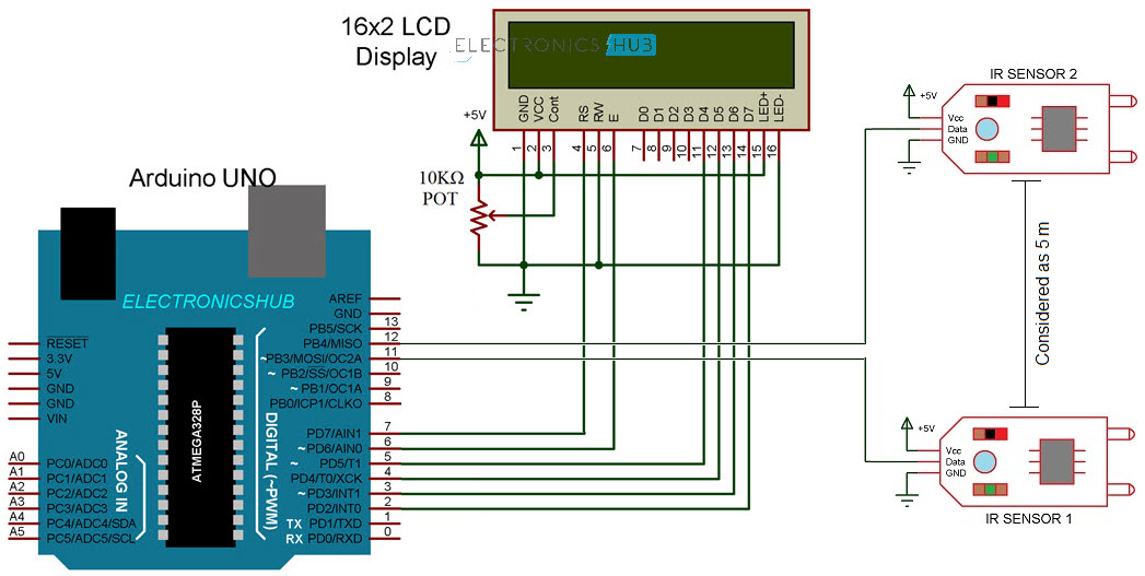
The following image shows the circuit diagram of the Arduino car speed detector project.
Components Required
- Arduino UNO
- IR Sensors x 2
- 16X2 LCD Display Module
- Breadboard
- Connecting Wires
- Power Supply
A Brief Note on IR Sensor
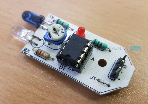
First of all, I have used two digital IR Sensors, which consists of an IR Transmitter (IR LED), an IR Receiver (Photo Diode), a Comparator IC and a few supporting components. The IR Transmitter and Receiver Pair are placed side-by-side so that they form a Reflective Type IR Sensor.
In this type, the IR Transmitter continuously emits Infrared radiations and if there is no object in front of the sensor, none of the Infrared radiation gets reflected back to the IR Receiver.
But if there is an object in front of the sensor, some of the infrared radiation hits the object and gets reflected back. This reflected radiation falls on the IR Receiver, which means that the sensor has detected the object.
Some IR Sensors has the option to produce both Analog and Digital Outputs but the module I have used has only Digital Output i.e. the output is HIGH when an object is detected and LOW when there is no object.
Circuit Design
The Digital OUT of the first IR Sensor is connected to Pin 11 of Arduino and the Digital OUT of the second IR Sensor is connected to Pin 12 of Arduino. Both the IR Sensors are provided with necessary power supply connections.
In order to view the car speed details, I have used a 16×2 LCD. Its data pins i.e. D4 – D7 are connected to Digital I/O pins 5 – 2. The RS and E pins of LCD are connected to pins 7 and 6 of Arduino. Rest of the connections are mentioned in the circuit diagram.
Code
How to operate Arduino Car Speed Detector Project?
- Make all the necessary connections with respect to the circuit diagram and upload the code to Arduino.
- Place the two IR Sensors on the edge of the breadboard so that the distance between them is approximately 10 centimeters.
- Simulate a car movement in front of the sensors either by using your hands or a toy car.
- Arduino calculates the speed and displays the result on the 16×2 LCD.
Working
The working of the Arduino based car speed detector project is very simple. Arduino continuously reads the inputs from the IR Sensors. When a car moving in front of the setup reaches the first sensor, Arduino becomes alert and capture a time stamp the moment the car leaves the first IR Sensor.
Another time stamp is recorded when the car reaches the second IR Sensor. Millis() function of Arduino used for capturing the time stamps.
Arduino then calculates the velocity by assuming the distance as 5 meters between the two IR Sensor and displays the result in kilometers per hour on the 16×2 LCD Display
Applications
- Helps in capturing speed of vehicles without any human involvement.
- This project can also be used as traffic logger, traffic counter and few other traffic related applications.
The post Arduino Car Speed Detector appeared first on Electronics Hub.
Controlling neurons with light -- but without wires or batteries
Tuesday, 1 January 2019
Physicists record 'lifetime' of graphene qubits
Researchers develop recyclable, healable electronics
Electronics often get thrown away after use because recycling them requires extensive work for little payoff. Researchers have now found a w...
-
Do you need a MOSFET gate resistor? What value should it be? And should it go before or after the pulldown resistor? If you’re a bit impati...
-
I was first introduced to logic gates when I was around 14 years old. I had heard that computers consisted of ones and zeroes. But I didn’t...
-
CMOS (Complementary Metal Oxide Semiconductor) The main advantage of CMOS over NMOS and BIPOLAR technology is the much smaller power dis...
