
I was first introduced to logic gates when I was around 14 years old. I had heard that computers consisted of ones and zeroes. But I didn’t understand what that really meant.
So I asked my father to explain it. And I loved his explanation because it was so simple and easy to understand. Read that article first if you’re not sure what a 1 and a 0 is yet.
Logic gates are components that we use for “doing stuff” with the 1s and 0s. You can combine them to create building blocks like flip-flops, adders, and more. Which you can use to build calculators, Arduinos, and even smartphones and computers!
Below, you’ll find an overview of the logic gates, their logic gate symbols, and how they work.
NOT gate/Inverter
The simplest logic gate of all is the NOT gate. It takes one bit as input (A). And it gives as an output (Y) what is NOT on the input. So if there is a 1 on the input, its output is 0. And if there is 0 on the input, its output is 1. It’s also called an inverter.

| Input (A) | Output (Y) |
|---|---|
| 0 | 1 |
| 1 | 0 |
AND gate
The AND gate takes two (or more) inputs and gives out a 1 if all the inputs are 1. Otherwise, it gives out a 0.
The truth table is below, but all you really need to remember is that the AND gate needs a 1 on input A and input B to give out 1.

| Input A | Input B | Output Y |
|---|---|---|
| 0 | 0 | 0 |
| 0 | 1 | 0 |
| 1 | 0 | 0 |
| 1 | 1 | 1 |
OR gate
The OR gate takes two (or more) inputs and gives out a 1 if any of the inputs are 1. Otherwise, it gives out a 0.
The truth table is below, but all you really need to remember is that the OR gate needs a 1 on input A or input B to give out 1.

| Input A | Input B | Output Y |
|---|---|---|
| 0 | 0 | 0 |
| 0 | 1 | 1 |
| 1 | 0 | 1 |
| 1 | 1 | 1 |
NAND gate

The NAND (or NOT AND) gate operates in the opposite way of the AND gate. It’s like if an AND gate had a NOT gate on its output:

| Input A | Input B | Output Y |
|---|---|---|
| 0 | 0 | 1 |
| 0 | 1 | 1 |
| 1 | 0 | 1 |
| 1 | 1 | 0 |
NOR gate

The NOR (or NOT OR) gate operates in the opposite way of the OR gate. It’s like if an OR gate had a NOT gate on its output.

| Input A | Input B | Output Y |
|---|---|---|
| 0 | 0 | 1 |
| 0 | 1 | 0 |
| 1 | 0 | 0 |
| 1 | 1 | 0 |
XOR gate
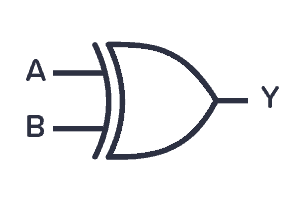
The XOR (or Exclusive OR) gate outputs 1 if its two inputs are not equal.
| Input A | Input B | Output Y |
|---|---|---|
| 0 | 0 | 0 |
| 0 | 1 | 1 |
| 1 | 0 | 1 |
| 1 | 1 | 0 |
XNOR gate

The XNOR (or Exclusive NOT OR) gate outputs 1 if its two inputs are equal. It basically works like an XOR gate with an inverter on the output.
| Input A | Input B | Output Y |
|---|---|---|
| 0 | 0 | 1 |
| 0 | 1 | 0 |
| 1 | 0 | 0 |
| 1 | 1 | 1 |
Using Logic Gates in Circuits
A logic gate can be built with transistors and usually comes as an Integrated Circuit (IC).
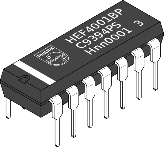
There are two classic IC series that contain a lot of the same functions; the 7400-series and the 4000-series.
The 7400-series is the oldest series. The 4000-series was introduced as a lower-power and more versatile option to the 7400. But today, several families of the 7400-series exist, some with similar properties as the 4000-series.
List of common 4000 series IC with pinouts, explanations, and example circuits
Complete list of ICs in the 4000-series
Complete list of ICs in the 7400-series
Copyright Build Electronic Circuits


No comments:
Post a Comment