
When you start learning about circuits, you’re bound to ask “what is ground?” at one point or another. Are you actually suppose to connect your circuit into the ground??
First of all: grounding in electronics is different from grounding in high voltage electrical systems. And this article is about electronics (although I’ll mention the other case at the end).
Grounding in electronics
I got an email from a reader a little while back:
«The ground symbol keeps appearing at different points in a circuit and I could not understand why a particular place was chosen for grounding. What is ground?»
Grounding something simply means connecting it to ground.
And in electronics, ground is just a name we give to a certain point in the circuit.
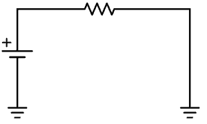
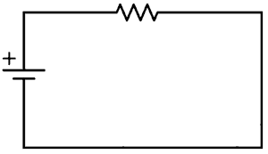
For example, in a circuit with one battery (with a positive and a negative terminal), we usually refer to the negative terminal as ground.
And to simplify drawing the circuit, we use a symbol.

So instead of drawing lines to all the places that should be connected to minus, you instead place the ground symbol there. This makes the circuit diagram much cleaner when there are a lot of connections to minus.
Flow of Current When the Ground Symbol is Shown
To see how the current flows in a circuit diagram with ground symbols, just connect all the points that have ground symbols. That is what you do when you build the circuit.
Circuits With Positive, Negative and Ground Connections
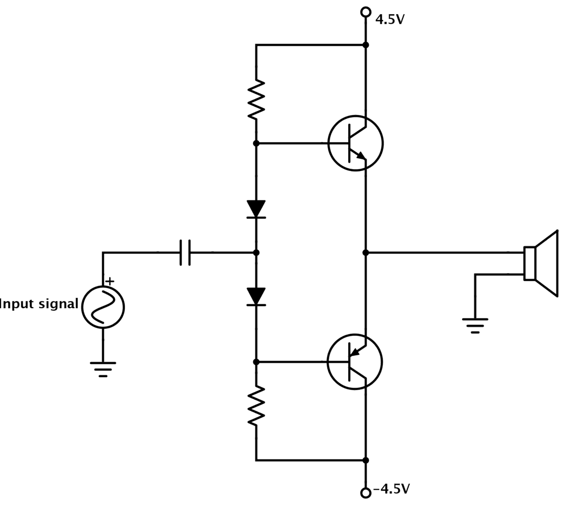
In some schematic diagrams, you’ll find a connection to a positive terminal, a negative terminal, and a ground terminal.
This is common in for example amplifier circuits:
So, how does this work?
In this scenario, the ground is the middle-point between the positive and the negative terminal. You can create these three voltage points by connecting two power sources in series:
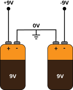
Since the ground terminal is in the middle between +9V and -9V, it’s normal to call it zero volts (0V).
Click here to learn what negative voltage is.
What is Ground in High-voltage Systems?
Sometimes though, the ground term refers to an actual connection to the ground/earth. But that is usually when talking about high-voltage systems.
That’s not my field, but for the curious ones – read more here: http://en.wikipedia.org/wiki/Ground_(electricity)
Questions? Let me hear ’em in the comments below!
Copyright Build Electronic Circuits


No comments:
Post a Comment