Thursday, 29 October 2020
Breakthrough quantum-dot transistors create a flexible alternative to conventional electronics
Wednesday, 28 October 2020
Device takes us closer to high-performing wearable and eco-disposable AI electronics
Tailoring 2D materials to improve electronic and optical devices
Monday, 26 October 2020
On-surface synthesis of graphene nanoribbons could advance quantum devices
Powering the future: New insights into how alkali-metal doped flexible solar cells work
Arduino Online Course by CircuitsToday
Dear reader, We are so delighted to announce our first online course in partnership with Udemy – the world’s biggest online course platform. We have launched our first course on Arduino with title “Arduino Course [Zero to Hero] – Learn Arduino by Doing Projects”. This is a complete course on Arduino, designed for students with [...]
The post Arduino Online Course by CircuitsToday appeared first on Electronic Circuits and Diagrams-Electronic Projects and Design.
Thursday, 22 October 2020
Turning streetwear into solar power plants
Reviewing multiferroics for future, low-energy data storage
A wearable sensor to help ALS patients communicate
Detecting early-stage failure in electric power conversion devices
Innovation spins spider web architecture into 3D imaging technology
Wednesday, 21 October 2020
Kitchen temperature supercurrents from stacked 2D materials
Friday, 16 October 2020
Octopus-inspired sucker transfers thin, delicate tissue grafts and biosensors
Thursday, 15 October 2020
Scientists develop 'mini-brains' to help robots recognize pain and to self-repair
Monday, 12 October 2020
Cap Half Full #6 – Repairing an old amplifier

In this episode, we repair an old Sanyo amplifier. In this episode, we find an old amplifier in the trash and we try to repair it. Will we able to? Listen and find out.
Listen to the Podcast
Show Notes


Copyright Build Electronic Circuits
Friday, 9 October 2020
Palladium catalysts can do it
Thursday, 8 October 2020
Engineering team develops novel miniaturized organic semiconductor
Electronic Schematic Symbols
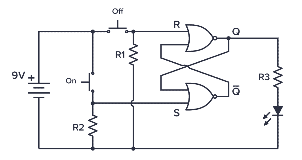
To be able to read schematics you must know the schematic symbols. But you don’t need to memorize them all. To start with, it’s usually enough to know the battery, resistor, capacitor, transistor, diode, LED, and switch.
Later when you come across symbols you don’t know, you can come back here to identify what it is.
Below is an overview of the most used symbols in circuit diagrams.
Battery
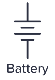
The symbol for a battery is shown below.
A large and a small line is suppose to represent one battery cell so that the image below would suggest a two-cell battery of 3 V. But usually people just draw the battery symbol with one or two cells no matter what voltage it is.
Capacitor
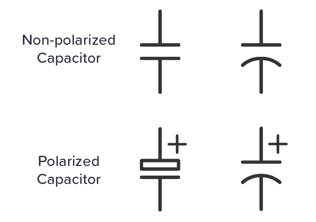
Capacitors are either polarized or not. The symbols that are commonly used for the two are shown below.
A polarized capacitor is marked with a “+” sign. It is important to distinguish between these two because the polarized capacitor needs to be placed correctly according to the “+” sign.
Resistor
The schematic symbol of the resistor are drawn in two different ways. The american style resistor is drawn as a zigzag resistor while the european style resistor is drawn as a rectangular resistor.
Even though I’m from Europe, I like to draw the zigzag version. I think it is easier to draw and looks better.


Potentiometer (Variable resistor)
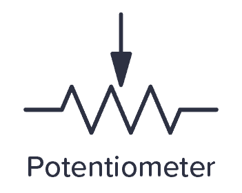
The potentiometer (or variable resistor) is drawn in several different ways. The symbol is usually drawn as a resistor with an arrow across it or pointing down on it as the one below.
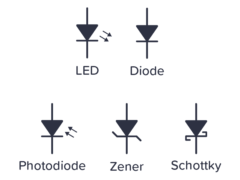
Diode
The diode family has several different symbols because there are several different types of diodes. Below is a standard diode, a Zener diode, a Schottky diode, and a Light-Emitting Diode (LED).
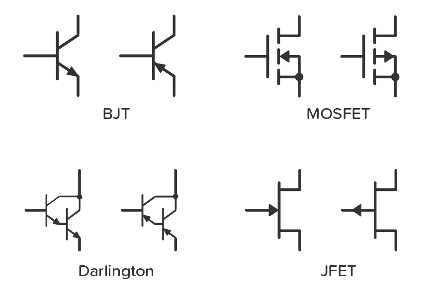
Schematic Symbols of a Transistor
The most common transistor types are the Bipolar Junction Transistor (BJT), Darlington Transistor, and the Field Effect Transistor (FET). The schematic symbols for these types are shown below:
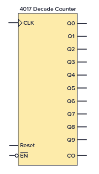
Integrated Circuit
An Integrated Circuit (IC) is usually shown as a rectangular box with pins. Below, an example of the CMOS IC 4017 is shown.
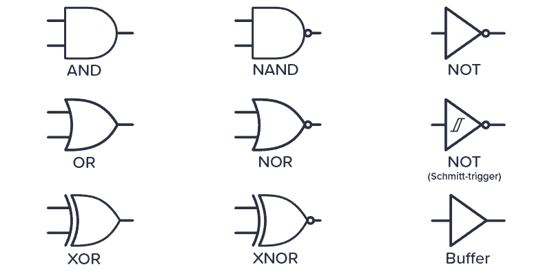
Logic Gates
Here are the schematic symbols for the logic gates:
Inductor
The inductor symbol looks like a coiled wire as this is what an inductor essentially is.

Transformer
The symbol of the transformer looks like two inductors with something in between them. Thats’s because that’s basically what a transformer is.

Switch
A switch can be represented in numerous ways in a circuit diagram. Below is a few examples:

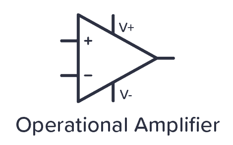
Operational Amplifier
The operational amplifier or “opamp” is represented as a triangle with two inputs and one output. In some cases, the power supply pins are removed, but you still need to connect them for it to work.
Power symbols
In larger circuit diagrams, you usually have a lot of connections to the power supply. To simplify, it’s common to use power symbols for ground and VDD (or VCC) as shown below.

In circuits where you have a dual supply, that is positive, neutral, and negative – you usually have a third power symbol that looks like the VDD symbol, just upside down.
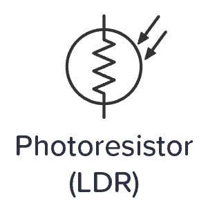
Photoresistor
The symbol for a photoresistor – or Light-Dependent Resistor (LDR) – looks like a resistor in a circle with arrows pointing inwards.
Crystal
The crystal is a component used to create a stable clock frequency, often for microcontrollers. In circuit diagrams it looks like this:

Fuse
Fuses are often used in higher-voltage circuits. The fuse symbol looks like this:

Return from Schematic Symbols to Electronic Schematics
Copyright Build Electronic Circuits
Wednesday, 7 October 2020
Intelligent nanomaterials for photonics
Monday, 5 October 2020
Turning diamond into metal
The best of both worlds: A new take on metal-plastic hybrid 3D printing
Friday, 2 October 2020
Physicists build circuit that generates clean, limitless power from graphene
3D printed 'invisible' fibers can sense breath, sound, and biological cells
Thursday, 1 October 2020
Flexible and biodegradable electronic blood vessels
Researchers develop recyclable, healable electronics
Electronics often get thrown away after use because recycling them requires extensive work for little payoff. Researchers have now found a w...
-
Do you need a MOSFET gate resistor? What value should it be? And should it go before or after the pulldown resistor? If you’re a bit impati...
-
I was first introduced to logic gates when I was around 14 years old. I had heard that computers consisted of ones and zeroes. But I didn’t...
-
CMOS (Complementary Metal Oxide Semiconductor) The main advantage of CMOS over NMOS and BIPOLAR technology is the much smaller power dis...