The pull-up resistor is very common and you’ll see it in digital circuits all the time. It’s just a resistor connected from an input up to VDD, the positive supply of the circuit.
For example on digital inputs on an Arduino. Or the input of digital chips such as the 4000-series IC.
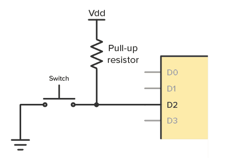
Pull-up resistors are used to make sure you have a HIGH state on the input pin when the button is not pushed. Without one, your input will be floating, and you risk that the input randomly changes between HIGH and LOW as it picks up noise in the air.
How To Choose a Pull-Up Resistor Value
Rule 1: The value can’t be too high.
The higher the pull-up value, the lower the voltage on the input becomes. It’s important that the voltage is high enough for the chip to see it as a HIGH, or logical 1, input.
For example, if you use a CD4017 with a power supply of 10V, it requires a minimum of 7V on the input for it to be seen as HIGH.
Rule 2: But it can’t be too small either.
If you for example choose 100 Ω, the problem is that you get a lot of current flowing through it when the button is pushed.
With a 9V power supply, you get 9V across 100 Ω, which is 90 mA. It’s an unnecessary waste of power, but it also means the resistor needs to withstand 0.81W. Most resistors can handle only up to 0.25W.
Rule of thumb
The rule of thumb when choosing a pull-up resistor is to choose a resistance value that is at least 10 times smaller than the input impedance (or the internal resistance) of the pin.
Often, a pull-up value of 10 kΩ will do the trick. But if you want to understand how it works, keep reading.
How Do Pull-Up Resistors Work?
You can think of the input pin of an integrated circuit (IC) as having a resistor connected to ground. This is called the input impedance:
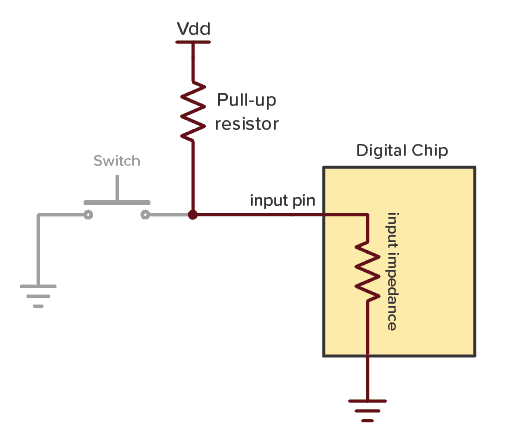
These two resistors make up a voltage divider. If you look at the standard voltage divider circuit, you can see that the pull-up resistor is R1 and the input impedance is R2:
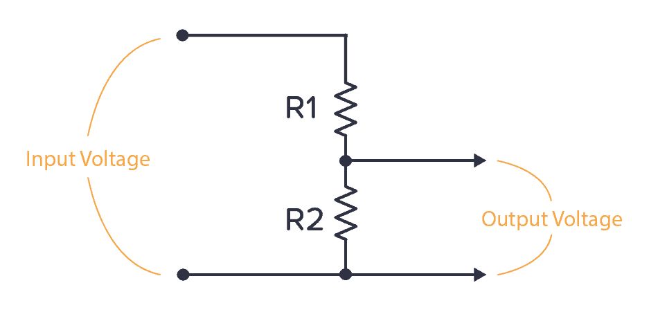
You can use the voltage divider formula to find the voltage on the input pin when the button is not pushed:

Below, I’ve renamed the components of the formula to fit the pull-up example. The input voltage is VDD from our pull-up example. And the output voltage is the voltage on the input pin. So the formula becomes:

Example Calculation
Let’s say your chip has an input impedance of 1MΩ (100kΩ to 1MΩ is normal for many chips). If your power supply is 9V and you choose a pull-up resistor value of 10 kΩ, what’s the voltage you get on the input pin?

You get 8.9V on the input pin, which is more than enough to act as a HIGH input.
In general, if you stick to the rule of thumb of using a pull-up resistor that is no more than ten times lower than the input impedance, you’ll make sure you always have a minimum of 90% of the VDD voltage on the input pin.
How To Find the Input Impedance of an IC
You can easily measure the input impedance of a chip. Impedance is actually a term for resistance that can change depending on frequency. But for this pull-up case, we only deal with DC currents.
Connect a pull-up resistor of for example 10 kΩ to the input of the chip, and measure the voltage on the input.
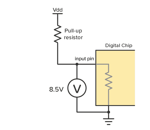
Let’s say you got 8.5V when you measured.
Use this to find the current flowing through the resistor by using Ohm’s law. The voltage drop across the resistor is 9V – 8.5V = 0.5V, so you get:

There is 0.05 mA flowing through the resistor, and thereby also through the input pin down to ground. Again, use Ohm’s law to find the resistance of something with a voltage drop of 8.5 V and a current of 0.05 mA:

The input impedance is 170 kΩ. That means a pull-up resistor for this input should be no more than 17 kΩ.
Questions?
What questions do you have about the pull-up resistor? Let me know in the comments field below!
Copyright Build Electronic Circuits


No comments:
Post a Comment