Friday, 30 April 2021
A silver lining for extreme electronics
Thursday, 29 April 2021
New optical hydrogen sensors eliminate risk of sparking
Small generator captures heat given off by skin to power wearable devices
Wednesday, 28 April 2021
Mapping the electronic states in an exotic superconductor
Nontoxic, flexible energy converters could power wearable devices
Tuesday, 27 April 2021
Silicon could be a photonics game-changer
New 2D superconductor forms at higher temperatures
Fully recyclable printed electronics developed
Wednesday, 21 April 2021
Fast material manipulation through a laser
Physicists map new route to control sound in thin films
New conductive polymer ink opens for next-generation printed electronics
Tuesday, 20 April 2021
Combining light, superconductors could boost AI capabilities
Sunday, 18 April 2021
Wearable sensors that detect gas leaks
New nanoscale device for spin technology
Saturday, 17 April 2021
3D-printed proton-conductive membrane paves way for tailored energy storage devices
Thursday, 15 April 2021
Giant electronic conductivity change driven by artificial switch of crystal dimensionality
Tuesday, 13 April 2021
No batteries? No sweat! Wearable biofuel cells now produce electricity from lactate
Friday, 9 April 2021
How To Edit Symbol in KiCad
I was recently asked how to edit a symbol in KiCad. The question was actually how to stretch a component that was in the standard library, so I made a quick walk-through on how to do that.
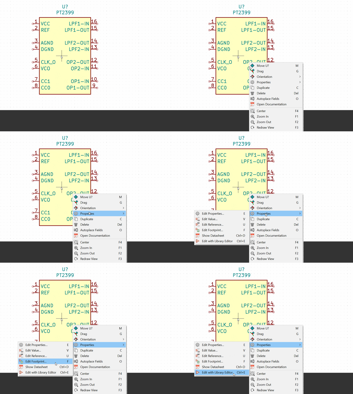
You can edit the symbol in the symbol editor. Just right-click on the symbol that you want to edit in the schematic and choose Properties, then Edit With Library Editor.

But you’re not allowed to overwrite the standard KiCad libraries, so unless you already have a custom library you need to create a new library to save the new symbol in first:
Click on File -> New Library
Choose where you want to save it. Then choose if this should be a Global library that all projects will have access to or a Local library that only this project will have access to.
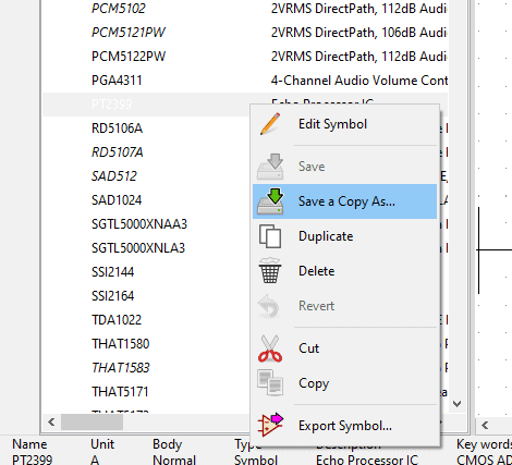
Now you need to create a copy of the symbol in your custom library. Just right-click on the symbol and choose to Save a Copy As…:

Find the library you created above and save the copy in that library.
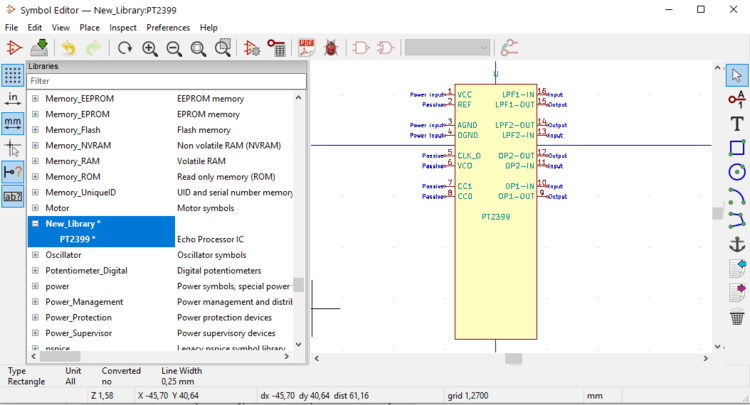
Now you can edit the symbol. Hold your mouse over the lower border of the component and press g on your keyboard. Then you can drag it and make it larger:

Then move the pins apart by holding your mouse over a pin and pressing m on your keyboard.
When you’re finished go to File and select Save. Then close the window.
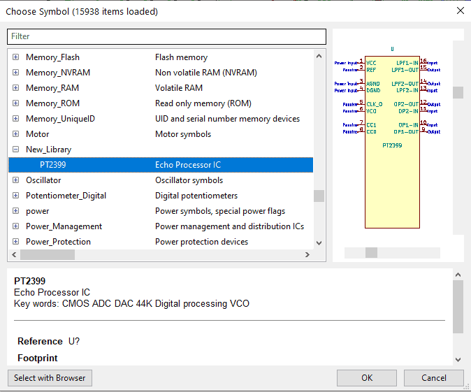
Now you can go back to your schematic and add the new symbol you just created:

I was a bit short on time, so I didn’t actually move the pins, but you get the picture.
Back to the main KiCad Tutorial
Copyright Build Electronic Circuits
Discovery could help lengthen lifespan of electronic devices
Thursday, 8 April 2021
Graphene: Everything under control in the quantum world
A breakthrough that enables practical semiconductor spintronics
The spintronics technology revolution could be just a hopfion away
Monday, 5 April 2021
A new, positive approach could be the key to next-generation, transparent electronics
Elasticity to position microplates on curved 2D fluids
Atom-based radio communications for noisy environments
Less than a nanometer thick, stronger and more versatile than steel
Me looking back at 5 years of Ohmify (it’s our birthday!)
5 years ago today, I launched Ohmify from my laptop while traveling in Colombia.
I had spent the previous night in a tree hut on the beach to recharge my batteries.
Now the moment had come…
I was finally launching Ohmify!
Something that I’d dreamed about for a long time.
I created Ohmify to be a place to learn electronics. But unlike most electronics courses and forums, I wanted this to be a welcoming place – even for complete beginners.
A place where there’s no such thing as a “stupid question”.
With practical, down-to-earth explanations, that both kids, adults, and seniors could understand.
My life looked quite different back then.
I was traveling all over the world while working from my laptop.
In Colombia, I fell in love with Pilar, who is now my wife.
We left Colombia together. Spent a few months in Europe before we found ourselves in Australia.
I have such fond memories of sitting in my shorts and t-shirt, sweating, in a tiny basement apartment, building electronics.
And whenever I needed any parts, I just walked over to Jaycar in the city center and got them.
Oh, how we loved Australia.
But we felt a bit too far from our families, so we decided to head for Norway.
When I first launched Ohmify, I didn’t have any expectations of what it would become.
I just felt inspired to create it, so I did.
But I was doing it along with ten other projects. Like writing Electronics For Kids and A Beginner’s Guide To Circuits. And developing electronics for the coffee roaster ROEST.
At this point I was getting messages from members regularly, telling me how much they loved the courses. Which motivated me to start saying ‘no’ to other projects. So that I could focus on Ohmify.
After some time in Oslo, my wife and I needed a change of environment. So we went back to Colombia for a few months.
I had a lot of fun doing an Arduino robot workshop with some locals. It was really nice to be doing this in a group. Which inspired me to make Ohmify more collaborative.
So I did a total remake of the whole Ohmify platform.
And it worked.
Suddenly the forum was booming with conversations, questions, and members showing the cool things they had made!
I started creating more courses. Which is what I love to do.
More members joined.
But I was doing web programming, marketing, design, accounting, customer support, creating new courses +++
And it was a lot for just one person.
That’s when Matthew appeared.
“Do you need help with anything?” he said.
“Uhm, yes, actually I do” I replied.
And just like that, Ohmify was no longer just me. We had become a team.
Matthew was just what I needed, and he was such a good addition to Ohmify. He understood what I was trying to do.
That freed up more time for me. More time to create courses and projects for our members.
Also, more mental space to come up with ideas.
So many ideas!
Which meant I needed more help. This led me to Ermin, who recently joined the Ohmify team.
Now we’re a team of three people, and we’re busier than ever. So many things to create! And so many interesting discussions to take part in over at the community forum.
We chat with our members every day. Hearing about what they’re struggling with. What inspires them. What they’d love to be able to do one day.
From that we get ideas. And we create new stuff.
I just checked, and we are soon reaching 500 different lessons available to Ohmify members!
Wow, that’s much more than I was able to imagine when I started.
Ohmify has grown a lot in 5 years.
I’m also a different man today compared to five years ago. My wife and I even have a little one on the way – which I’m sure will turn our lives upside down (in a good way).
I have no idea what Ohmify will be in another 5 years. All I know is that it will be exactly what it’s supposed to be.
The path appears as we walk it.
To celebrate our birthday, we’re doing a promotion for the next few days. If you sign up for the annual subscription before Monday night, you’ll get a beginner’s component kit + a Blinking LED soldering kit as a welcome gift.
Keep On Soldering!
Oyvind @ build-electronic-circuits.com
Copyright Build Electronic Circuits
Friday, 2 April 2021
Kirigami-style fabrication may enable new 3D nanostructures
Thursday, 1 April 2021
Researchers link silicon atoms on surfaces
Researchers develop recyclable, healable electronics
Electronics often get thrown away after use because recycling them requires extensive work for little payoff. Researchers have now found a w...
-
Do you need a MOSFET gate resistor? What value should it be? And should it go before or after the pulldown resistor? If you’re a bit impati...
-
I was first introduced to logic gates when I was around 14 years old. I had heard that computers consisted of ones and zeroes. But I didn’t...
-
CMOS (Complementary Metal Oxide Semiconductor) The main advantage of CMOS over NMOS and BIPOLAR technology is the much smaller power dis...