In this tutorial, you’ll learn how to use an ultrasonic sensor. Specifically, you’ll learn how to use the HC-SR04 module with an Arduino to measure the depth of a water tank.
An ultrasonic sensor is one of those things that some people don’t like getting into just because it sounds complex to use and understand. But the fact is, it’s one of the most accessible and fun accessories for those who like to dabble in microcontrollers.

This is especially true when talking about an Arduino, as there are a couple of very reliable libraries out there. And for those looking to get even more into the technicalities of the sensor, the GitHub repositories are open and available to all.
There are two things that make this type of sensor easy to use. Firstly, connecting it is very straightforward as it only requires direct connections between the module and microcontroller. Secondly, the module makes the functionality of the sensor relatively simple. You’ll understand this part better when I get into the workings of it later on.
What You’ll Need
To build this project you’ll need the following components
- HC-SR04 Ultrasonic Sensor Module
- Arduino UNO
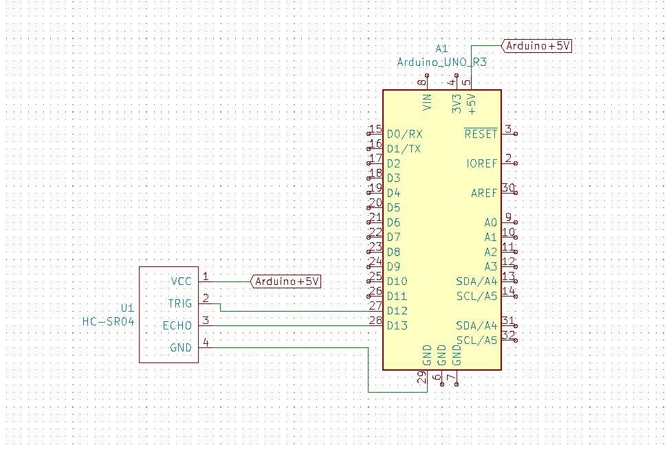
And the circuit diagram looks like this:
And you’ll need the following software:
- Arduino IDE
- HCSR04 ultrasonic sensor lib by gamegine
Keep in mind that, in general, any kind of microcontroller should be able to run this type of project, but we’ll specifically be working with Arduino IDE. So to follow these instructions, your board must at least be compatible with that.
How Does an Ultrasonic Sensor Work?
The basic principle of an ultrasonic sensor is pretty basic: It sends out a sound wave from its speaker. When the sound hits an object, this creates an echo that bounces back to the sensor. The sensor uses a microphone to detect the echo.
The speed of sound waves is 343 m/s. So by multiplying this with the time the signal took to return, you get the distance that the signal traveled.
Since the signal first traveled to the object, then back, you can get the distance to the object by dividing by 2.
The HC-SR04 module needs a 10 µs pulse from the Arduino to trigger the sound wave being emitted from the module. The Arduino then waits for an incoming pulse from the module and uses the time it took to get the distance.
But you don’t have to think about this since the library you’re going to use includes everything needed.
How the Code Works
Regarding the code, the first thing to consider is the libraries that must be included. For this we only need one:
#include “HCSR04.h”After this, we must declare all the variables and constants that we are going to use. This section is split into two parts: pin configuration constants and the variables associated with storing the data:
/*PIN CONFIG*/
const int trig = 12; //Trigger pin
const int echo = 13; //Echo pin

*/VARIABLES*/
float distBuff; //Buffer for the raw distance taken by the sensor
int tankFinal; //Final percentage value for how full the tank is
float allDist; //The sum of all the distances in allDist
float avgDist; //The average of all the distances in allDist
int i; //Random variable used to control the loop
Here we initialize the class of the ultrasonic sensor module and as you can see, we add the pins that it is going to use:
HCSR04 hc(trig, echo); //HCSR04 Initialization (trig pin, echo pin)Within the setup function, all we need to do is initialize it for serial communication:
void setup() {
  Serial.begin(9600); //Serial communication initialization
}
Then, inside the loop function we code the process taken by the Arduino which is going to be repeated over and over again:
void loop() {
allDist = 0; //Restart the distance sum
for(i = 0;i < 25;i++){
delay(5); //delay between each reading to avoid an error
distBuff = hc.dist(); //Taking distance
if(distBuff > 0 && distBuff < 301) //We ensure we only take values between the physical possible ranges
{
allDist = allDist + distBuff; //Summing the distances
}
}
avgDist = allDist / 25; //Dividing the distances to get the average
tankFinal = map(avgDist, 2, 300, 100, 0); //Converting the average into percentage
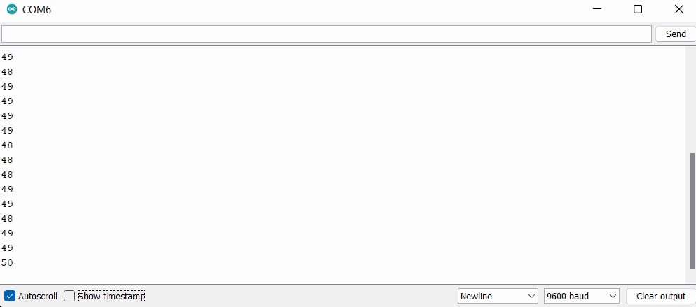
Serial.println(tankFinal); //Print the percentage value
}The code first ensures that the variable in charge of storing the sum is empty, then we have a loop in charge of taking 25 readings from the sensor, ignoring any readings outside the distance of the water tank. After all the readings are taken, we calculate the average and then use the map function to convert the distance to the percentage of the tank.
Issues Encountered While Testing
Although I have used this sensor module in other projects, I tried a slightly different approach to make it work this time: I added a smoothing algorithm for the data coming from the module. Without the smoothing, I could just print the data obtained each time, but in this case, I take a certain number of readings and calculate the average. Nothing extraordinary or anything that I haven’t done with many other projects before.
However, I was getting a recurring error in my readings, which materialized in this way:
- The code starts.
- The code perfectly reads the height between my table and the ceiling at 49%.
- I use an object to simulate something at 90%, which works as intended.
- Then the readings get stuck at around 70% when I remove the object. They don’t go any lower.
- I use an object to simulate something at 90% again, which again works as intended.
- The readings then return to the correct state at 49% when I remove the object.
- This issue then repeats again from 3.
I spent a large amount of time checking the library that I was using and made several changes to it. I also tried restarting the module every time I took a reading, but nothing seemed to work and I kept having the same issue. I began to think the module itself was faulty, but after further testing, I came to an important realization.
When I actually monitored the raw data itself, the readings gave perfect results, but this would stop as soon as I stopped printing the raw data. So I attempted to simulate the printing time by adding a delay. I began with a long delay of 30ms, which successfully eliminated the issue. After that, I tried delays from 1ms until I got successful readings at 5ms.
This kind of behavior is not completely out of the ordinary for me as some modules do need a bit of time to process data to avoid various types of interference. The catch was that if that had been the problem, it would have happened with every reading, but in this case, it was switching back and forth every time it went over 70%. I looked for some information in one of the many datasheets of the module, and one of them suggested a 60 ms measurement cycle “in order to prevent trigger signal to the echo signal”.
Honestly, I still don’t know what that means. Truth be told, I haven’t been able to find a more professional datasheet about this module, but the module does need some added time for its measurement cycle to work without issue. This may not be obvious in most online tutorials since they all use a print function after each reading, which takes time and works as an unintended measurement cycle delay.
Complete Code
#include "HCSR04.h"

/*PIN CONFIG*/
const int trig = 12; //Trigger pin
const int echo = 13; //Echo pin

/*VARIABLES*/
float distBuff; //Buffer for the raw distance taken by the
int tankFinal; //Final percentage value for how full the tank is
float allDist; //The sum of all the distances taken by the sensor
float avgDist; //The average off all the distances in allDist
int i; //Random variable used to control the loops

HCSR04 hc(trig, echo); //HCSR04 Initialization (trig pin , echo pin)

void setup() {
  Serial.begin(9600); //Serial communication initialization
}

void loop() {
  allDist = 0; //Restart the distance sum

  for(i = 0;i < 25;i++){
    delay(5); //delay between each reading to avoid an error
    distBuff = hc.dist(); //Taking distance
    if(distBuff > 0 && distBuff < 301) //We ensure we only take values between the physical possible ranges
    {
      allDist = allDist + distBuff; //Summing the distances
    }
  }

  avgDist = allDist / 25; //Dividing the distances to get the average
  tankFinal = map(avgDist, 2, 300, 100, 0); //Converting the average into percentage
  Serial.println(tankFinal); //Print the percentage value
}
Testing the HC-SR04 With a Water Tank
For a more realistic testing environment, I used a water tank that I have in my house. This is an underground water tank and had been getting a healthy amount of water over the last few days, so I was expecting the tank to be over half full.
Two things to bear in mind are that when doing real-life tests, the ultrasonic sensor can receive pulses from a fairly wide range of directions, so testing it in a very open space can give you shaky readings. Plus, you need to be careful with the material you are testing it with: cushions, for instance, are really bad at making sound bounce.
According to the manufacturer, the tank is 3-metres deep, but no one seems sure about the rest of the dimensions. In this case, it isn’t important, but if you want to get a bit more creative, calculating the volume would help you estimate the time it takes for the tank to empty if it doesn’t receive any water.
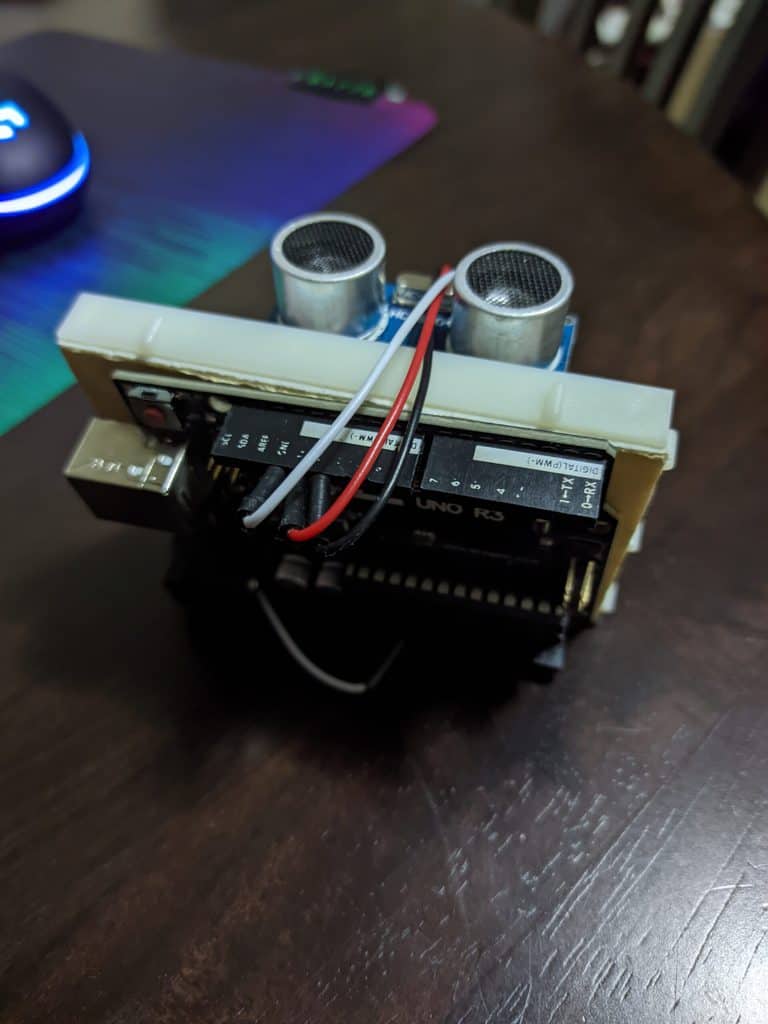
Making a prototype for this sensor is not that complicated since connecting it up is straightforward enough. Here you can see how I attached my Arduino UNO to a small breadboard to have an easier time testing it, and the schematic of the connection:
One thing to be aware of is that if anyone testing this would like to enclose the device, they need to leave the “eyes” of the device outside the enclosure. After this, it is just a matter of setting an output device, which in my case was just my PC. As you can see in the code, I’m repeatedly sending the processed data through serial communication, so you can use the serial monitor to show the results:
However, I wanted to see the results in a more interesting way so I used a program called Processing. Here, Processing receives the serial data, and converts it into the graphic and number you can see below:
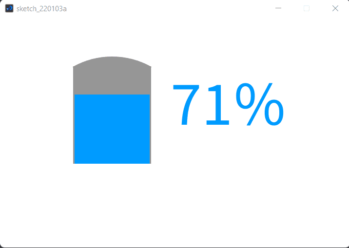
This was the actual result of the test, and below you can see the tank and how the test was performed:
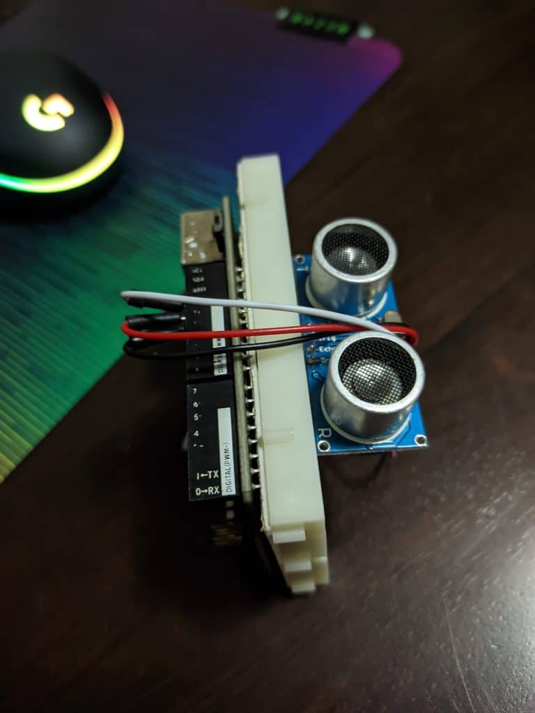
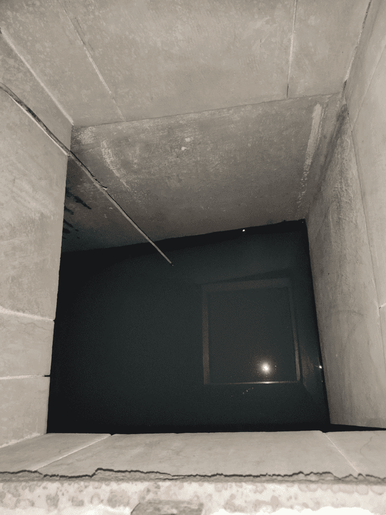
In the following video, you’ll be able to see how the percentage of the tank decreases the further I take the sensor away from the water. Note that this test was done one day later which is why the initial percentage is less than the 71% shown above.
An ultrasonic sensor can sound intimidating but, in reality, it is quite simple to use, and the best part is that it can allow you to do many things. For instance, it is often used for obstacle detection in robots, and as with other things in electronics, the only limit is the imagination of the creators themselves!
Another very convenient thing is that the module is easy to find and inexpensive. I know that I kind of skipped the Processing part, but that is mostly software-related and would require its own article.
Copyright Build Electronic Circuits


No comments:
Post a Comment