A NOT gate (or inverter) is a logic gate where the output is the opposite of the input. So you can say that the output is NOT the same as the input. It’s often called an inverter since it inverts the input.
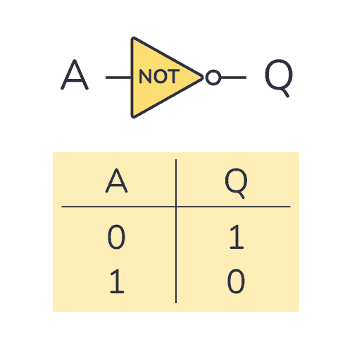
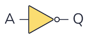
The schematic symbol for an inverter is like a buffer, just with a circle at the output to indicate that it’s an inverted version of the input.
The logic or Boolean expression for a NOT gate is  which means that:
Q is the opposite of A
Truth Table
A NOT gate can only have one input. And its truth table is pretty simple since there are only two possible states; the input being HIGH (or “1”) or the input being LOW (or “0”).
NOT Gate Truth Table
| Input A | Output Q |
|---|---|
| 0 | 1 |
| 1 | 0 |
Build an Inverter with Transistor-Resistor Logic
You can build an inverter/NOT gate from transistors and resistors. This technique is called resistor-transistor logic (RTL).
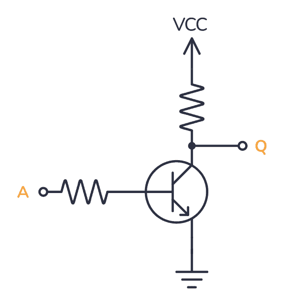
If A is HIGH, the transistor turns on. When the transistor is turned on, Q is pulled LOW through the transistor. If A is LOW, the transistor is off and Q is pulled HIGH through the resistor up to VCC.
It’s fun to know how you could build it with transistors and resistors. But it’s not really practical to use that many components just to make a simple logic gate. Luckily, there are many ICs that have NOT gates that you can use out-of-the-box.
IC Alternatives with NOT Gates/Inverters

If you want to experiment and build circuits with NOT gates, you’ll find them in both the 4000 IC series and the 7400 IC series:
- 4041: Four NOT gates/inverters (with buffers)
- 4049: Six NOT gates/inverters
- 4069: Six NOT gates/inverters
- 40106: Six NOT gates/inverters with Schmitt trigger
- 4572: Four NOT gates/inverters (plus a few other gates)
- 74HC04: Six NOT gates/inverters (HC is the family, can also be LS/HCT/…)
- 74HC05: Six NOT gates/inverters (HC is the family, can also be LS/HCT/…)
- 74HC14: Six NOT gates/inverters with Schmitt trigger (HC is the family, can also be LS/HCT/…)
These should all be available as hobbyist-friendly through-hole chips. Just make sure you buy the DIP package version.
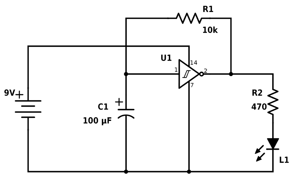
Inverter Example Circuit: Blinking LED
A fun circuit to build with inverters is the blinking LED circuit. In the following circuit, the Light-Emitting Diode (LED) is blinking continuously. Note that this circuit will only work with Schmitt trigger inverters. So you can build it for example with the CD40106B chip or the 74C14 chip.
The resistor R1 and the capacitor C1 sets the blinking speed.
Next Step in the Logic Gates Tutorial
Check out the other articles in this logic gates tutorial:
NOT Gate/Inverter – (You are here)
AND Gate
NAND Gate
OR Gate
NOR Gate
XOR Gate
XNOR Gate
Back to the Logic Gates Overview
Copyright Build Electronic Circuits


No comments:
Post a Comment