A Half Adder is a digital circuit that adds binary numbers. In this tutorial, you will learn how it works, its truth table, and how to implement one using logic gates.

What is a Half Adder?
A Half Adder is a digital circuit that carries out the addition of binary numbers. It’s the simplest of digital adders and you can build one using only two logic gates; an XOR gate and an AND gate.
The Half Adder can add only two 1-bit numbers. The difference between a Half Adder and a Full Adder is that the first one does not have a Carry input.
All the possible combinations of 1-bit binary additions are shown below:
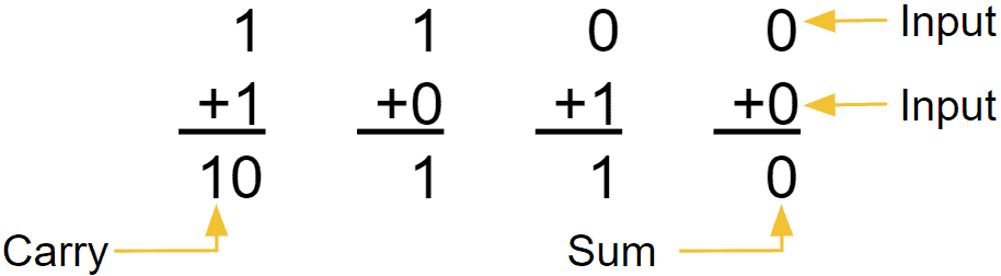
You need two bits to represent the result since the highest possible result of adding two 1-bit numbers is 2 (“10” in binary).
You can add this into a truth table using the four possible combinations of 1-bit binary additions given before. The adder takes two inputs, A and B, and generates two outputs, one for the Sum (S) and another for the Carry (C). So the truth table becomes:
| Input A | Input B | Output S | Output C |
|---|---|---|---|
| 0 | 0 | 0 | 0 |
| 0 | 1 | 1 | 0 |
| 1 | 0 | 1 | 0 |
| 1 | 1 | 0 | 1 |
How does the Half Adder work?
To understand how to create a Half Adder circuit you can use its truth table. The first thing you need to do is separate the S output and build its own truth table.
| Input A | Input B | Output S |
|---|---|---|
| 0 | 0 | 0 |
| 0 | 1 | 1 |
| 1 | 0 | 1 |
| 1 | 1 | 0 |
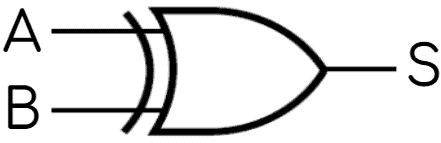
If you know your logic gates, you might notice that this looks exactly like the truth table of an XOR gate. And you’re right. So to implement the Sum (S) output, you’ll need an XOR gate:
Next, it’s time to focus on the C output:
| Input A | Input B | Output C |
|---|---|---|
| 0 | 0 | 0 |
| 0 | 1 | 0 |
| 1 | 0 | 0 |
| 1 | 1 | 1 |
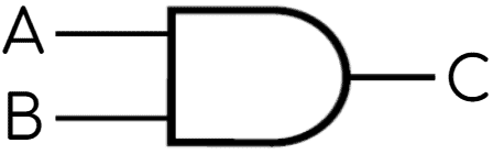
If you examine it carefully, you’ll see that it behaves the same as an AND gate since it only returns one when both inputs are one. This means that to create the C output you can use an AND gate:
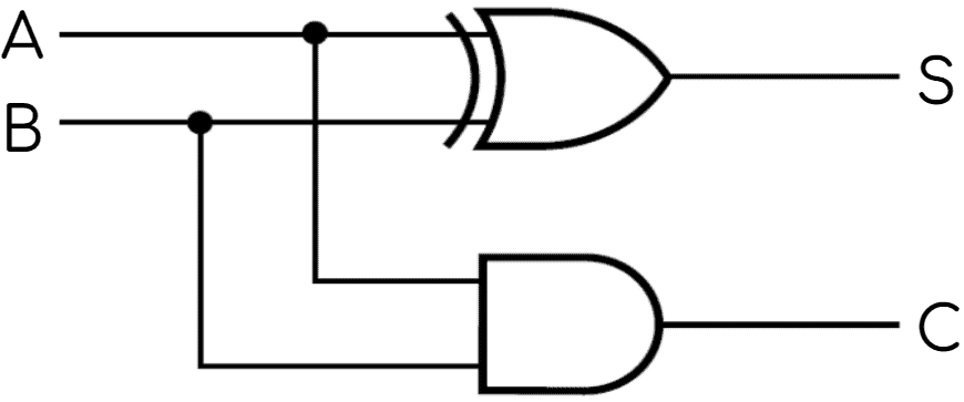
Finally, you can combine the circuits for producing the S and C outputs to build the complete Half Adder circuit diagram:
Half Adder simulation
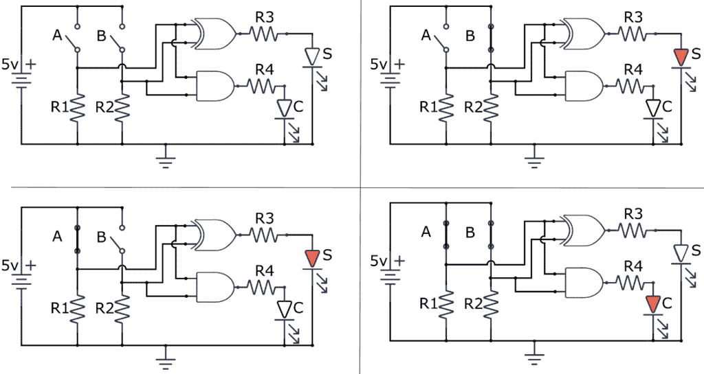
To demonstrate this adder circuit works, you’ll find a simulation below. Simple switches represent the A and B inputs. The S and C outputs are represented by LEDs, where a lit LED means “1” and an unlit LED means “0”.
Questions?
Do you have any questions about how this adder circuit works? Let me know in the comments below.
Copyright Build Electronic Circuits


No comments:
Post a Comment