This is a practical guide to the Insulated Gate Bipolar Transistor, or IGBT. You’ll learn how to use it from a practical standpoint – without going into the physics of what it looks like on the inside. The IGBT is often presented as something complex and advanced. But when you strip away the physics explanation and get down to practice, putting it into a circuit is straightforward.
By the end of this guide, you will be able to use an IGBT and build your first simple circuit with it.
What is an IGBT?
An Insulated Gate Bipolar Transistor (IGBT) is a special type of transistor that can be useful in circuits where there is a lot of current that needs to be switched on and off. It’s a mix between a MOSFET and a BJT transistor.
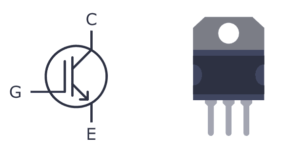
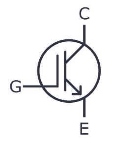
It has three pins – Collector, Emitter, and Gate. As the name suggests the gate terminal is insulated from the rest, so no current flows into the gate, just like the MOSFET. When you turn it on, current flows between the collector and emitter pins.
The gate voltage controls how much current flows through the emitter-collector terminals. In other words, the input voltage controls the output current. So IGBT is a voltage-controlled transistor.
IGBT vs MOSFET
If you already know how MOSFETs work, you’re good to go, because IGBTs work the same way in a circuit. And the truth is that in most practical cases, you can think of the IGBT as a MOSFET.
The main difference is that the IGBT transistor can handle much higher currents and voltages than the MOSFET transistor.
Depending upon the device, an IGBT can handle currents as high as 500A and up. The gate voltage required to switch on an IGBT is usually around 4-8V.
Types of Insulated Gate Bipolar Transistors
There are two types of IGBT:
- Punch-through IGBT: Allows current to flow from collector to emitter only, not the other direction This type of IGBT is used in DC circuits and is also known as an asymmetrical IGBT.
- Non-punch-through IGBT: Allows for current to flow both ways – from collector to emitter – or from emitter to collector. This type of IGBT is used in AC circuits and it is also known as a symmetric IGBT.
So if you’re building an AC circuit, use the asymmetrical (punch-through) version. And if you’re building a DC circuit, use the symmetrical (non-punch-through) version.
Practical Examples of Using an IGBT in a Circuit
Because it can handle such high currents, IGBTs are typically used in power electronics. You’ll find it in switch mode power supplies, in circuits that drive heavy loads such as electric motors, in air conditioners, refrigerators, and more.
Below are some practical examples using Insulated Gate Bipolar Transistors in a project:
Building a Tesla Coil at Home
Probably one of the coolest Halloween decorations out there is the Tesla Coil! The classic way of building one is by using spark gaps. But an IGBT can be used instead to make a solid-state Tesla coil.
You can build your own Tesla coil by combining an IGBT with standard components like a 555 Timer, a 74HC14, and other basic electronic components.
Repairing an Induction Cooker
When his induction cooker broke, Johannes from Sweden wanted to see if it was possible to repair it himself. He opened his cooker, and after some research, found that the transistors of the cooker had been broken. After ordering spare parts for around $30, his cooker was working perfectly again.
But he didn’t stop there. He went on to add Bluetooth support and is now controlling his cooker from his phone. Read the whole story over at Johannes’ GitHub page.
Controlling an Electric Car with Custom Electronics
New electric cars have big motors that need lots of current. Cars use brushless motors, and they need to be controlled properly. IGBTs are great for this job.
If you’re interested in these types of circuits, I highly recommend checking out etischer’s homemade EV motor controller. He’s even made a full walkthrough of the circuit in video form.
Build Your First IGBT Circuit
Now that you know the basics, it’s good to get some practical experience. It’s time to build your first IGBT-based circuit – a variable voltage supply. You can build this circuit on a breadboard. You will need the following parts:
- An IGBT (such as WG30NC60)
- A 1K resistor
- A 10K potentiometer
- A 12V power supply
- Any output load such as a DC motor, fan, or a bulb
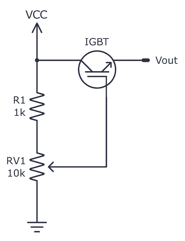
Connect the circuit as shown in the schematic above.
How It Works
When you turn the potentiometer, the voltage across the gate of the IGBT changes. This will increase or decrease the current across the collector-emitter terminal.
To test this, you can connect a DC motor to the output to see it change speed as you turn the 10K pot. Or see the brightness of the bulb change when connected across the output. If you want to use the circuit for high voltages and currents, use a heat sink for the IGBT and solder the components on a PCB with suitable wires.
Copyright Build Electronic Circuits
No comments:
Post a Comment