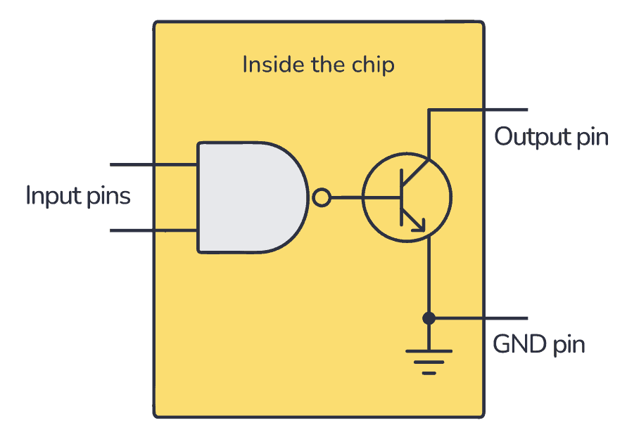
An open collector output is not a normal high/low output. Instead, these outputs are connected via a transistor. And the collector of the transistor is available at the pin. For example, if you have a NAND gate with an open-collector output, it will look like this:

So when the output from the NAND gate is ‘1’, the transistor that is connected to the output will be turned on. When the output from the NAND gate is ‘0’, the transistor will be off.
Note: Some chips use MOSFET transistors instead of BJT. In that case, this technique is called open-drain instead, but the concept is exactly the same.
How To Use an Open Collector Output?
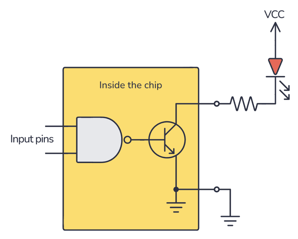
Here’s a simple example with an LED: To turn on the LED when the NAND gate output is ‘1’, you must connect the LED from your positive supply, via a resistor, to the open-collector output:

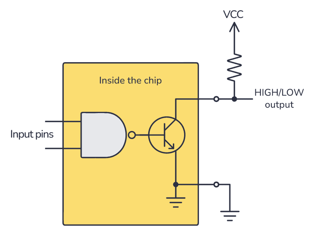
But if you instead want to get your standard high/low output, you could achieve this by connecting a resistor from the output up to your positive supply. Then your NAND gate output pin becomes a standard high/low output:

But it’s important to notice that the output will be inverted! A logical HIGH from the NAND gate turns the transistor ON so that the output voltage on the pin becomes low. A logical LOW leaves the transistor OFF so that the output voltage on the pin becomes HIGH.
The advantage of using open-collector outputs is that you can choose your HIGH voltage level to make it compatible with whatever the voltage of the next stage is. The resistor acts as a pull-up resistor and pulls the voltage up to VCC.
Where to find open collector chips?
There are several chips with open collector outputs in the 7400 series of integrated circuits. Here are a few examples:
- 74×03: An IC with four open-collector NAND gates
- 74×09: An IC with four open-collector AND gates
- 74×33: An IC with four open-collector NOR gates
- 74×136: An IC with four open-collector XOR gates
- 74×266: An IC with four open-collector XNOR gates
Copyright Build Electronic Circuits
No comments:
Post a Comment