Monday, 3 December 2018

How to build a robot – Club de Arduino

It was sunny and hot.

I was wearing a backpack and I could feel the sweat building up on my back.

But I had to walk fast.

Because I was late.

And because the locals had told me to be careful in the center.

I had emailed with Thomas, the founder of the makerspace Göra, before coming here.

We had discussed electronics workshops but decided that it would be better to meet in person to figure out the details.

I did not know what to expect.

Across the street, I saw it.

The Göra sign that I had seen in the street view of Google maps.

I met with Thomas and some of the other members.

And I got the grand tour.

I especially liked the machine for printing your own t-shirt design.

But they didn’t have much of an electronics section.

Thomas told me that at the moment, they didn’t have a big group of electronics people.

Instead, he asked me if I wanted to help out with an Arduino club.

To help start attracting more electronics people.

I accepted.

And that’s how I became a part of Club de Arduino in Medellin.

Every week, I’ll be sharing my notes from the previous week.

Check out the notes released so far:

Copyright Build Electronic Circuits

Borophene advances as 2D materials platform

Physicists synthesized 2D atom-thin sheets of boron with large crystal domains, which are needed to make next-gen electronics.

Colloidal quantum dots make LEDs shine bright in the infrared

A group of researchers report on the development of a colloidal quantum-dot light emitting diode with unprecedented quantum and power conversion efficiencies in the infrared range. The study has proven that these devices can also be integrated in inorganic solar cells and may lead to even higher efficiencies.

Robots in the rain

It’s raining a lot these days.

So, it’s nice to be inside building robots!

These last days I’ve been tinkering with an H-bridge, which is a part for a robot we’re building.

I’m in Medellin and as a part of “Club de Arduino” at Göra Makerspace we’re building a sumo robot.

A sumo robot is a fighter robot.

It is built to try and push another robot out of a ring:

https://youtu.be/suyPkO0apak

The H-bridge is a circuit to control a motor to go forward or backward.

And it makes it easy to use from a microcontroller such as an Arduino.

I’m writing an article on how to build one as we speak – that I hope should be out within a few days.

Ultimately, this NEEDS to become a new Ohmify course.

I’ll keep you updated as we go along.

Not sure what Ohmify is? Learn more here:

https://ohmify.com/join/

Keep On Soldering!
Oyvind @ build-electronic-circuits.com

Copyright Build Electronic Circuits

Graphene unlocks new potential for 'smart textiles'

The quest to create affordable, durable and mass-produced 'smart textiles' has been given fresh impetus through the use of the wonder material graphene.

Saturday, 1 December 2018

DFRobot FireBeetle ESP8266 Review

In this project, I will review the DFRobot FireBeetle ESP8266 IoT Module and see how to set it up in order to use it in our IoT Projects. In the process, I will demonstrate a simple hook-up guide using the Arduino IDE.

Unboxing DFRduino and DFRobot FireBeetle ESP8266

I have received two modules from DFRobot: one is the DFRduino UNO R3 and the other is the DFRobot FireBeetle ESP8266 IoT Module. The package is neatly packed with two boxes and also stuffed with packing foam.
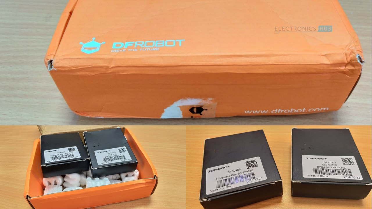
DFRobot FireBeetle ESP8266 Review Unboxing

DFRduino UNO

First, let me unpack and give a brief overview on the DFRduino UNO board and later, I will unpack the DFRobot FireBeetle ESP8266 IoT Board and review it thoroughly.   

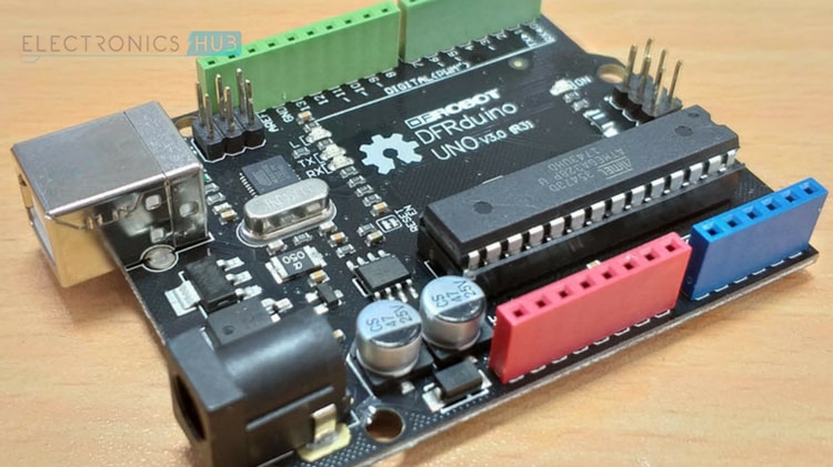
The first box consists of the DFRduino UNO Rev 3, which is an Arduino UNO Compatible board from DFRobot. It is packed in an anti-static bag and once you cut open the bag, you can see the DFRduino UNO in its black PCB.
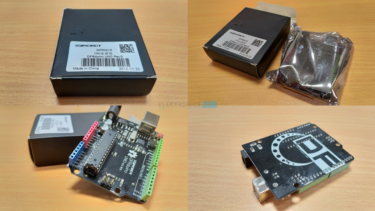
DFRobot FireBeetle ESP8266 Review DFRduino UNO Unboxing

The DFRduino UNO has all the features of a regular Arduino UNO i.e. a DIP ATmega329p, headers for Digital I/O, Power, Analog IN, USB-to-Serial, 16MHz Crystal etc.

If you notice the DFRduino UNO board, the female headers are color coded, which is kind of a cool and unique feature.  

  • Green: Digital I/O Headers
  • Blue: Analog IN Headers
  • Red: Power Headers      

DFRobot FireBeetle ESP8266 Review DFRduino UNO

DFRobot FireBeetle ESP8266

Let me now proceed with unpacking the item of interest, the DFRobot FireBeetle ESP8266 IoT Module. Like DFRduino UNO, it is also packed in an anti-static bag but you get a second bag with a bunch of male and female headers.
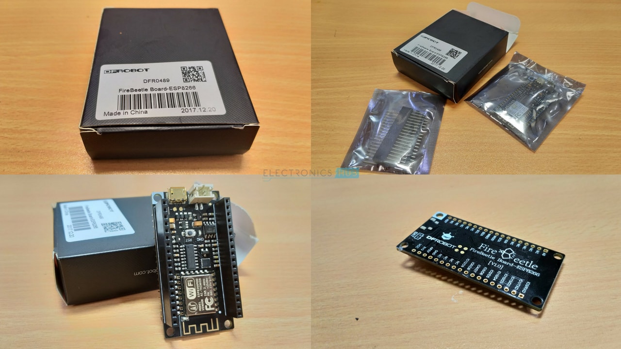
DFRobot FireBeetle ESP8266 Review FireBeetle Unboxing

Opening the package, you get the DFRobot FireBeetle ESP8266, which is a Arduino Nano sized black PCB with gold colored antenna trace and header mounting holes. Also, in the other pack, you get 18 pin Female and Male Headers (couple of each).

As the pins of the board are not soldered with any headers, you can solder yourself either male or female header as per your needs. Unless you are using the GPIO’s or the other peripherals, there is no need for any soldering tasks as you can plug-in the MicroUSB cable and start using it.

Apart from the regular ESP8266 related stuff, you get an additional hardware for charging Li-Ion Batteries. I will show all the components on the DFRobot FireBeetle ESP8266 board a little later.
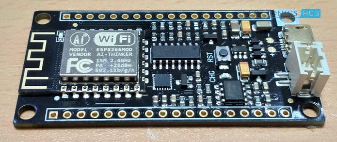
DFRobot FireBeetle ESP8266 Review FireBeetle

Overview of DFRobot FireBeetle ESP8266 IoT Board

The DFRobot’s FireBeetle is a series of low-power development board aimed for Internet of Things (IoT) implementation. DFRobot FireBeetle series has mainly two boards: one is based on the ESP8266 and the other is based on ESP32.

DFRobot FireBeetle ESP8266, as the name suggests, is an ESP8266 based IoT development board based on the ESP8266EX SoC from Espressif Semiconductors.

If you are following ElectronicsHub for some time, you might have come across my implementation of IoT projects using ESP866 ESP-01 Module. Even though the ESP-01 Module is also based on the same ESP8266EX SoC, the main disadvantage is its lack of sufficient I/O and various protocols.

The DFRobot FireBeetle ESP8266 Module succeeds in this aspect by including the regular WiFi Connectivity, TCP/IP Stack, UART along with numerous GPIO Pins, ADC, SPI, PWM, I2C and even I2S.
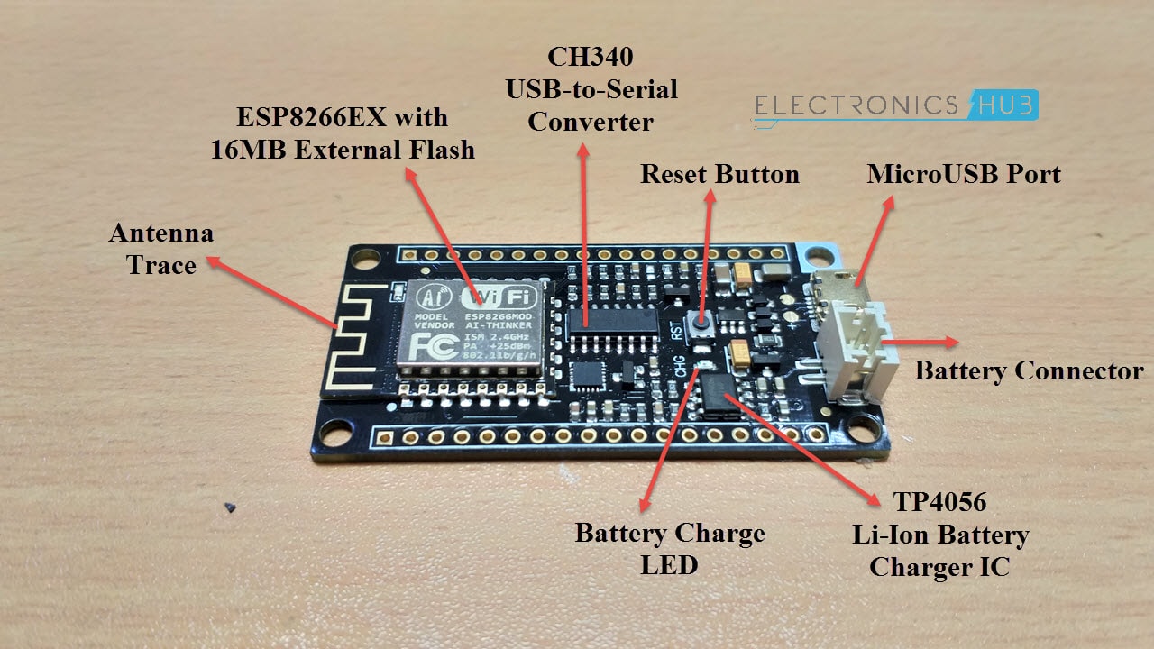
DFRobot FireBeetle ESP8266 Review FireBeetle Components

NOTE: The above picture says 16MB of Flash but it is actually 16Mb.

Another important feature is it has 16Mb of External Flash interfaced through SPI. This is in contrast to 8Mb Flash on my ESP-01 Module.

The USB-to-Serial Conversion is taken care by the CH340 IC, which can also be found in various Arduino clones as well. Also, the FireBeetle ESP8266 features auto reset. This means that you don’t have to around the Reset and the GPIO0 pins (as those two pins are responsible for enabling flash mode or normal mode).

All this stuff i.e. GPIO Pins, Flash, Interfaces etc. is directly associated with ESP8266. But there is one other important feature that is included in the DFRobot FireBeetle ESP8266 Module. The feature is a dedicated IC for charging Li-Ion Batteries.

The famous Li-Ion Battery Charger IC TP4056 is integrated on the board with dedicated connector for the Battery. The maximum charging current that is supported by this board is 500mA (although the TP4056 is capable of handling charging current up to 1A).

A dedicated charging LED is provided on the board. If the battery connector terminals are open i.e. when no battery is connected, the LED blinks. It becomes stable when the board is charging a battery and turns off when the battery is fully charged.
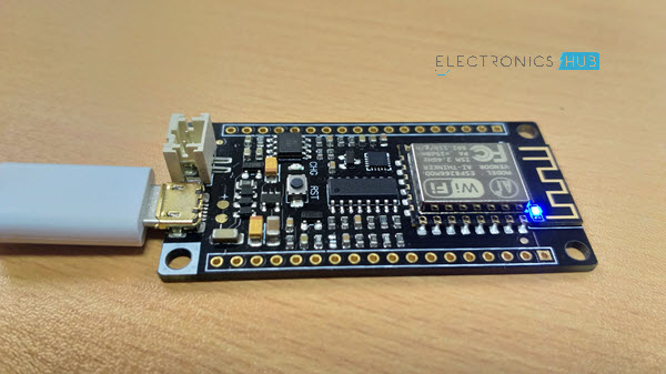
DFRobot FireBeetle ESP8266 Review FireBeetle LED

Coming to the software part of the module, it is compatible with Arduino Programming environment (Arduino IDE) and hence, programming the DFRobot FireBeetle ESP8266 Module will not be an issue.

Additionally, the DFRobot FireBeetle ESP8266 Module also supports MicroPython, and RTOS SDK as well (if you are interested).

Features and Pin Description of DFRobot FireBeetle ESP8266

Features

I have already discussed some of the features of the DFRobot FireBeetle ESP8266 Module but here is a list of all the features as specified by the manufacturer (DFRobot).

  • Based on ESP8266EX (which is based on Tensilica L106 MCU)
  • Supports Arduino IDE, MicroPython and RTOS SDK in Linux
  • Has integrated WiFi (IEEE802.11b/g/n @2.4GHz) and TCP/IP Stack
  • Hardware support for charging Li-Ion Battery (with max current of 500mA)
  • Includes 11 Digital IO, 1 Analog IN, SPI, I2C and I2S

Pin Description of DFRobot FireBeetle ESP8266 Module

The following image gives a general idea on the pin description of the DFRobot FireBeetle ESP8266 Module. The module has 36 Pins (18 on the either side) out of which most of the pins are NC.
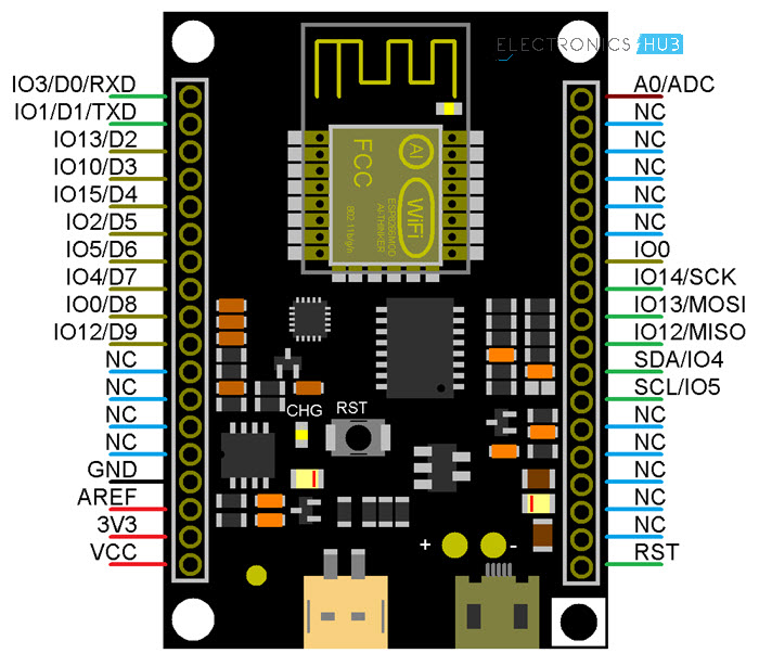
DFRobot FireBeetle ESP8266 Review FireBeetle Pin Description

Now that we have seen the features and pin description, let me proceed with hooking up the board with the computer and programming it. In the process, I will also show you how to setup the Arduino IDE for the DFRobot FireBeetle ESP8266 Module. So, lets get started with that.

Setting Up the Arduino IDE

Before setting up the Arduino IDE, first, connect the FireBeetle ESP8266 to the computer with the help of a USB to MicroUSB Cable. Assuming you are using a Windows Computer, it should automatically detect the device and download the necessary CH340 Drivers from the internet, which happened in my case.
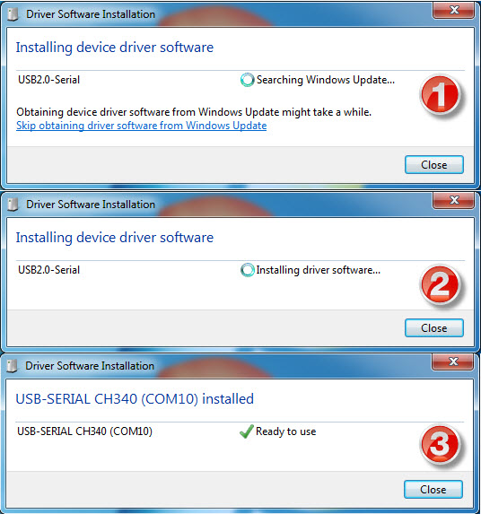
DFRobot FireBeetle ESP8266 Review FireBeetle Drivers

If your computer, for any reason, doesn’t detect the device and automatically install the drivers, then you can manually install by downloading the driver from this link.

Let us now proceed with setting up the Arduino IDE. In that, the first step is to install the FireBeetle Board through the board manager. So, first, copy the following link and place it in the “Additional Boards Manager URLs” in preferences (File -> Preferences).
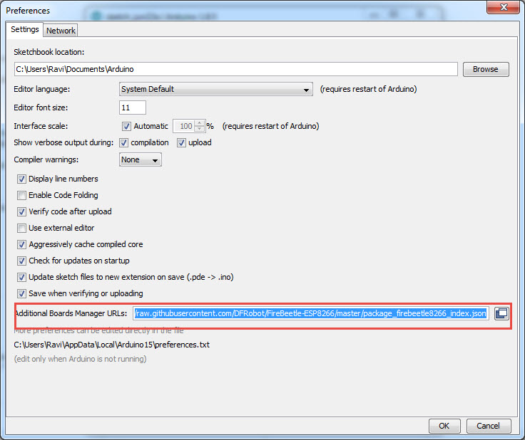
DFRobot FireBeetle ESP8266 Review FireBeetle Arduino Preferences

NOTE: If you already have an URL in that field, you can add extra URLs by separating them with comma. In my case, I already have ESP8266 related Link.

Now go to Tools -> Board -> Boards Manager.. and search for “FireBeetle”. You can see the “FireBeetle-ESP8266 by DFRobot” option. Click on install.
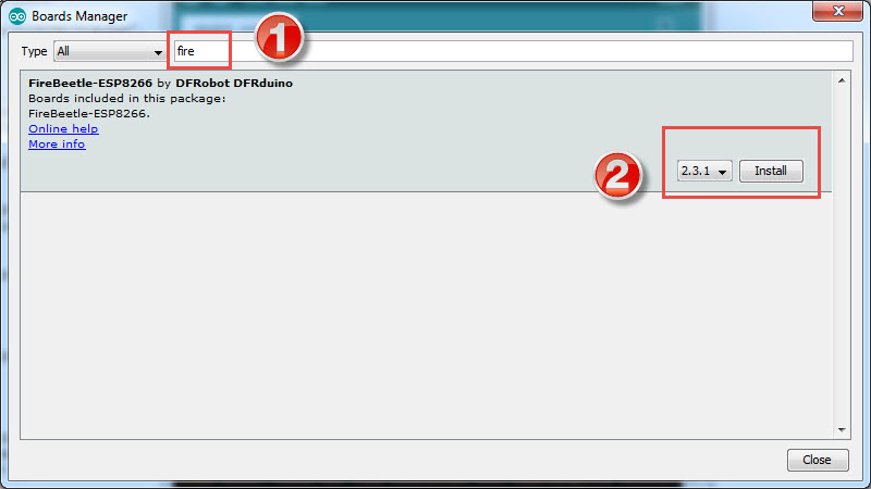
DFRobot FireBeetle ESP8266 Review FireBeetle Arduino Board Install

After the Boards Manager installs the FireBeetle, you need to select it by once again going to Tools -> Board -> FireBeetle-ESP8266 (from the bottom of the list).

You can also select the appropriate COM Port number below the Board option and leave the rest of the settings as it is.
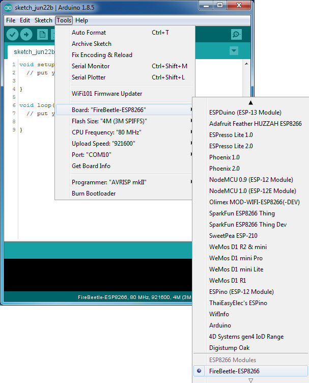
DFRobot FireBeetle ESP8266 Review FireBeetle Board Selection

Uploading Code to DFRobot FireBeetle ESP8266 Module

Now that you have set the Arduino IDE for programming DFRobot FireBeetle ESP8266 Module, let us upload two sample codes for testing out whether the board is functional or not.

Blink Code

The first code is a simple Blink Sketch, where the LED connected to GPIO Pin 2 of the FireBeetle ESP8266 Module will start to blink.
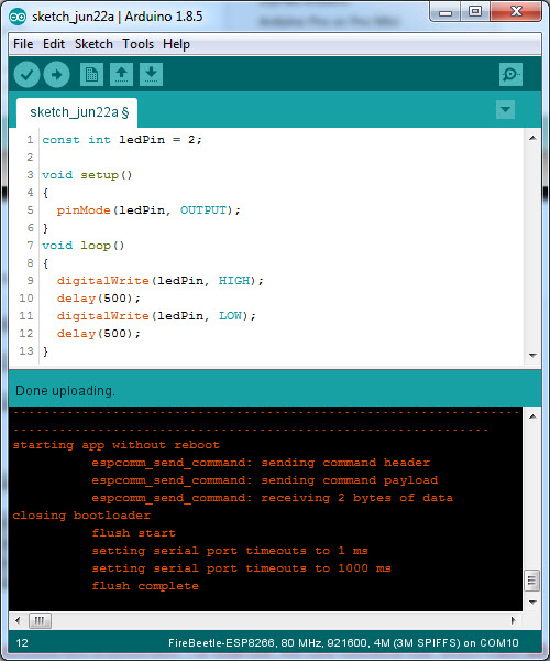
DFRobot FireBeetle ESP8266 Review FireBeetle Code Upload

WiFi Scan Code

The second code is for scanning the available WiFi Networks in range and displaying a list in the serial monitor of the Arduino IDE.
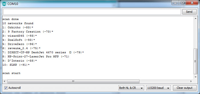
DFRobot FireBeetle ESP8266 Review FireBeetle WiFi Scan

Conclusion

In this project, I have started working on the DFRobot FireBeetle ESP8266 Module after unboxing, setting up the programming environment and uploading some sample codes.

Few points to note about the DFRobot FireBeetle ESP8266 Module:

  • The module has on-board USB-to-Serial Converter, MicroUSB Port and voltage regulator. This is important for me because of my experience with ESP8266 ESP-01 module, where I had to design a perf board to insert the module and add level converter for RX and TX (UART) pins.
  • Also, the module comes with 16Mb of flash, which means you can program it with RTOS SDK.
  • The on-board Li-Ion Battery Charger is an additional feature (which I may end up not using it).
  • As of now, I’m not sure about the firmware aspects of the Module i.e. the version, how to update (although the DFRobot page says the module supports OTA Updates) and how to communicate through AT Commands.
  • I will try to update on the AT Commands aspect as they are important (at least for me).

The post DFRobot FireBeetle ESP8266 Review appeared first on Electronics Hub.

How to Send an Email using ESP8266 WiFi Module?

In this project, I will show you how to Send an Email using ESP8266. For this project, I will be using the DFRobot FireBeetle ESP8266 IoT Board. Sending an e-mail with the help of the ESP8266 Module will be a step forward in the IoT Implementation.

Introduction

With Internet of Things (IoT) expanding, the scope of the IoT applications is growing from controlling appliances to monitoring devices (like sensors) and sending e-mails.

By sending e-mails from you ESP8266 Module, you can know the status of any sensor you are monitoring or you can receive an emergency e-mail in case of burglary or an intruder alert.

So, without further delay, let me show you all the steps required to Send an Email using ESP8266 WiFi Module.

ESP8266 Board

As said earlier, I will be using the DFRobot FireBeetle ESP8266 board in this project to send e-mails. You can use any ESP8266 Module and I have tested this procedure with my ESP-01 ESP8266 Board and it worked just fine.

DFRobot FireBeetle ESP8266 Review FireBeetle

Since the DFRobot FireBeetle ESP8266 board has all the required components like the MicroUSB Port, 3.3V Regulator, etc. I don’t need to make any extra connections with respect to the board.

All I need to do is to plug-in a MicroUSB cable in the port and connect it to a computer (with the drivers being already installed and Arduino IDE is already setup).

This is one of the main reasons for choosing the DFRobot FireBeetle ESP8266 board over my regular ESP-01 Module.

So, I suggest you to go through the hook-up guide of the DFRobot FireBeetle ESP8266 board as described in the following project: DFROBOT FIREBEETLE ESP8266 REVIEW AND HOOK-UP GUIDE.

SMTP Server Setup

In order to send e-mails from ESP8266 Module, you need to follow the SMTP protocol. Hence, an SMTP Server is required to send the e-mails and the ESP8266 will act as an SMTP Client.

I have tried the Gmail’s SMTP Settings several times to send email using ESP8266 but it was not fruitful. So, I have decided to use a third-party SMTP Server and I found “SMTP2GO” as a reliable choice.

Send an Email using ESP8266 SMTP2GO Home

So, go to the SMTP2GO website and register with a free account. After creating an account, the first step is to create the SMTP Username and SMTP Password. In fact, the moment you confirm your e-mail address and first login to SMTP2GO, this is the information that you’ll get.

Leave the username as it is i.e. the e-mail address and change the SMTP Password with your own choice. Note that this is SMTP Password and is different from the SMTP2GO Login Password.

Make a note of the two i.e. SMTP Username and SMTP Password.  

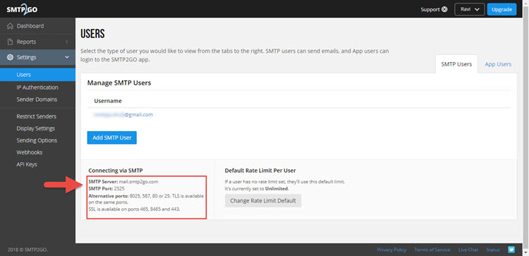
Now, enter the dashboard of the SMTP2GO app and on the left access bar, click on “Settings” and then on “Users”.

In that, you can see the information regarding the SMTP Server and PORT number. It is usually as follows:

  • SMTP Server: mail.smtp2go.com
  • SMTP PORT: 2525

Send an Email using ESP8266 SMTP2GO Server

Note down this information as you need to use this data in the code.

Encoding Username and Password

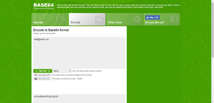
You need to encode your SMTP Username and SMTP Password to Base64 format with ASCII Character Set. For this, you can either use an Arduino Library or a website called BASE64ENCODE.

Send an Email using ESP8266 Base64 Encode

Enter your SMTP Username and Password separately and note the encoded content. For example, if your email address is test@gmail.com, it would be encoded as dGVzdEBnbWFpbC5jb20=.

And if your password is “testpassword” (excluding the quotes), it would be encoded as dGVzdHBhc3N3b3Jk.  

Code

Now, let me show you the necessary code in order to Send an Email using ESP8266.

In the code, make necessary changes like SSID, Password of your WiFi Connection, Sender and Receiver E-Mail Address, Base64 Encoded SMTP Username and SMTP Password.

Explanation of the Code

The initial section of the code is simple used to connect the ESP8266 WiFi Module to the Internet. If the connection is successful, you will get an IP Address.

Next is the actual code for sending the e-mail. The code can be divided into 8 stages.

Stage 1: In stage 1, you will be connecting to the SMTP Server on a PORT. This is done using the command client.connect(SMTP_SERVER, SMTP_PORT). In response, you will get a 220 code.

Stage 2: Greet the SMTP Server with EHLO Command (Previously HELO Command). The command is client.println(“EHLO www.example.com”);

If the connection is successful, you will get a 250 Response Code.

Stage 3: Stage 3 is to authorize the user with AUTH LOGIN Command. The command is client.println(“AUTH LOGIN”);. You will get a Response 334 for success.

Stage 4: Send the encoded SMTP Username and Password one after the other. The commands are client.println(“Base64, ASCII encoded username”); and client.println(“Base64, ASCII encoded password”);.

If the authentication is success, you will get a 235 Response.

Stage 5: Now its time to send the mail from string where you have to enter the sender’s email address using the format MAIL FROM:<”+String(from)+’>’;.

The command is client.println(“MAIL From: sender@gmail.com”);

Stage 6: Then send the rcpt to string using the format RCPT TO:<”+String(to)+’>’;. The command is client.println(“RCPT To: receiver@gmail.com”);.

Stage 7: Send the “DATA” followed by the Message body of the e-mail. The commands are

client.println(“DATA”);

client.println(“To:  receiver@gmail.com”);

client.println(“From: sender@gmail.com”);

client.println(“Subject: ESP8266 test e-mail\r\n”);

client.println(“This is is a test e-mail sent from ESP8266.\n”);

client.println(“Second line of the test e-mail.”);   

stage 8: Finally, terminate the mail with “.” and send the quit command.

client.println(“.”);

client.println(“QUIT”);

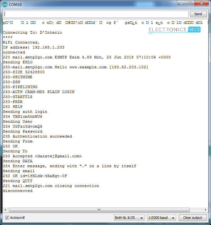
All these commands and responses will be shown in the serial monitor of the Arduino IDE.

Send an Email using ESP8266 Output

If you follow all the mentioned steps, you will be able send an email using ESP8266 successfully.       


The post How to Send an Email using ESP8266 WiFi Module? appeared first on Electronics Hub.

Researchers develop recyclable, healable electronics

Electronics often get thrown away after use because recycling them requires extensive work for little payoff. Researchers have now found a w...