Monday, 13 November 2023

Arduino Buzzer Tutorial: Play Melodies with Your Arduino

In this quickstart tutorial, you’ll learn how to control a passive buzzer using your Arduino UNO to play a simple melody. By the end, you’ll have a basic understanding of how to incorporate sound into your Arduino projects.

Materials Needed

Arduino Buzzer Schematic Diagram

Refer to the schematic diagram provided to connect your passive buzzer to digital pin 8 on the Arduino board.
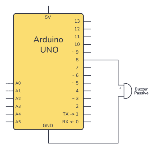
Arduino buzzer schematic diagram

Breadboard Layout

This is a very simple circuit to connect.

  1. Connect one lead of the passive buzzer to the digital pin 8 on the Arduino.
  2. Connect the other lead to a ground (GND) pin on the Arduino.

Check out the breadboard image below to see how you can connect this circuit to a breadboard.
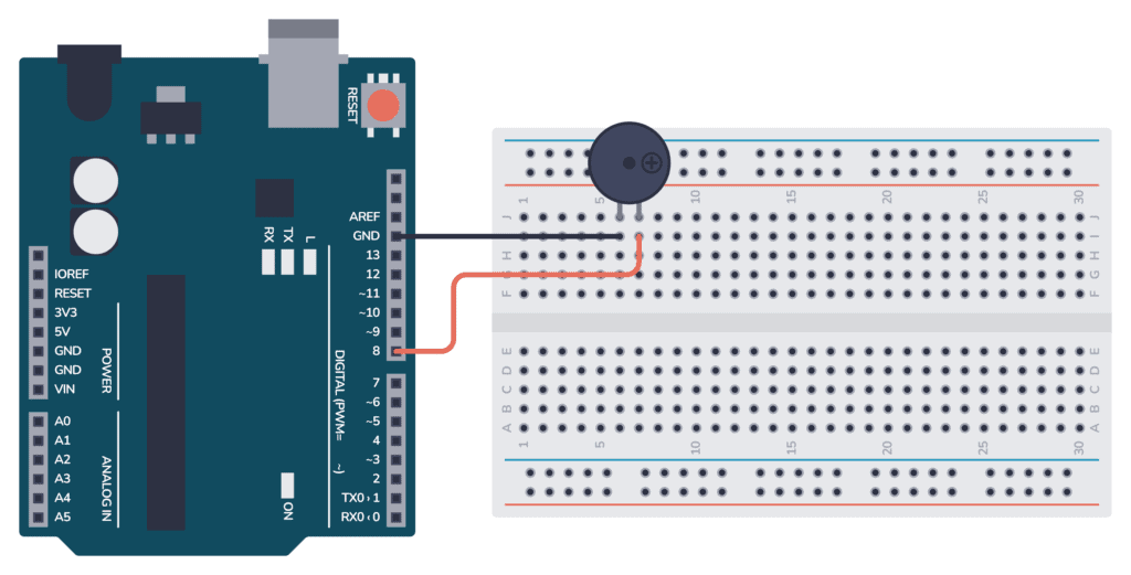
How to connect the arduino buzzer circuit

Arduino Buzzer Example Code

The code uses the tone() function in Arduino to play tones. The function has three parameters; pin, frequency, and duration. The melody is defined through the array melody[], and the timing is controlled through the array noteDurations[].

A 0 in the melody array represents a rest or pause in the melody, and the corresponding duration values in noteDurations determine the length of these pauses.

Copy the code below into your Arduino IDE. This code will play a simple melody through the buzzer.

// Define the buzzer pin
int buzzerPin = 8;

// Define the "Happy Birthday" melody
int melody[] = {
  NOTE_C4, NOTE_C4, NOTE_D4, NOTE_C4, NOTE_F4, NOTE_E4, // "Happy Birthday to You"
  NOTE_C4, NOTE_C4, NOTE_D4, NOTE_C4, NOTE_G4, NOTE_F4, // "Happy Birthday to You"
  NOTE_C4, NOTE_C4, NOTE_C5, NOTE_A4, NOTE_F4, NOTE_E4, NOTE_D4, // "Happy Birthday dear [Name]"
  NOTE_AS4, NOTE_AS4, NOTE_A4, NOTE_F4, NOTE_G4, NOTE_F4 // "Happy Birthday to You"
};

// Define the note durations
int noteDurations[] = {
  4, 4, 4, 4, 4, 2,
  4, 4, 4, 4, 4, 2,
  4, 4, 4, 4, 4, 4, 2,
  4, 4, 4, 4, 4, 2
};

// Note definitions for the melody
#define NOTE_C4 262
#define NOTE_D4 294
#define NOTE_E4 330
#define NOTE_F4 349
#define NOTE_G4 392
#define NOTE_A4 440
#define NOTE_AS4 466
#define NOTE_C5 523

void setup() {
  // Iterate over the notes of the melody:
  for (int thisNote = 0; thisNote < 24; thisNote++) {
    // To calculate the note duration, take one second divided by the note type.
    int noteDuration = 1000 / noteDurations[thisNote];
    tone(buzzerPin, melody[thisNote], noteDuration);

    // To distinguish the notes, set a minimum time between them.
    int pauseBetweenNotes = noteDuration * 1.30;
    delay(pauseBetweenNotes);

    // Stop the tone playing:
    noTone(buzzerPin);
  }
}

void loop() {
  // No need to repeat the melody in the loop for this example.
  // The setup() is enough to play it once.
}

Testing and Troubleshooting

  • After uploading the code, the buzzer should play the melody.
  • If you don’t hear any sound, check your connections and ensure the buzzer is functional.
  • Verify that you have selected the correct board and port in the Arduino IDE before uploading.

Define Your Own Melody

In the code above, we only defined the frequencies of the notes that we needed for the melody. If you want to create other melodies, you might need other notes. Copy the code below and save it as pitches.h, then include this file in your code to have all notes available.

#define NOTE_B0  31
#define NOTE_C1  33
#define NOTE_CS1 35
#define NOTE_D1  37
#define NOTE_DS1 39
#define NOTE_E1  41
#define NOTE_F1  44
#define NOTE_FS1 46
#define NOTE_G1  49
#define NOTE_GS1 52
#define NOTE_A1  55
#define NOTE_AS1 58
#define NOTE_B1  62
#define NOTE_C2  65
#define NOTE_CS2 69
#define NOTE_D2  73
#define NOTE_DS2 78
#define NOTE_E2  82
#define NOTE_F2  87
#define NOTE_FS2 93
#define NOTE_G2  98
#define NOTE_GS2 104
#define NOTE_A2  110
#define NOTE_AS2 117
#define NOTE_B2  123
#define NOTE_C3  131
#define NOTE_CS3 139
#define NOTE_D3  147
#define NOTE_DS3 156
#define NOTE_E3  165
#define NOTE_F3  175
#define NOTE_FS3 185
#define NOTE_G3  196
#define NOTE_GS3 208
#define NOTE_A3  220
#define NOTE_AS3 233
#define NOTE_B3  247
#define NOTE_C4  262
#define NOTE_CS4 277
#define NOTE_D4  294
#define NOTE_DS4 311
#define NOTE_E4  330
#define NOTE_F4  349
#define NOTE_FS4 370
#define NOTE_G4  392
#define NOTE_GS4 415
#define NOTE_A4  440
#define NOTE_AS4 466
#define NOTE_B4  494
#define NOTE_C5  523
#define NOTE_CS5 554
#define NOTE_D5  587
#define NOTE_DS5 622
#define NOTE_E5  659
#define NOTE_F5  698
#define NOTE_FS5 740
#define NOTE_G5  784
#define NOTE_GS5 831
#define NOTE_A5  880
#define NOTE_AS5 932
#define NOTE_B5  988
#define NOTE_C6  1047
#define NOTE_CS6 1109
#define NOTE_D6  1175
#define NOTE_DS6 1245
#define NOTE_E6  1319
#define NOTE_F6  1397
#define NOTE_FS6 1480
#define NOTE_G6  1568
#define NOTE_GS6 1661
#define NOTE_A6  1760
#define NOTE_AS6 1865
#define NOTE_B6  1976
#define NOTE_C7  2093
#define NOTE_CS7 2217
#define NOTE_D7  2349
#define NOTE_DS7 2489
#define NOTE_E7  2637
#define NOTE_F7  2794
#define NOTE_FS7 2960
#define NOTE_G7  3136
#define NOTE_GS7 3322
#define NOTE_A7  3520
#define NOTE_AS7 3729
#define NOTE_B7  3951
#define NOTE_C8  4186
#define NOTE_CS8 4435
#define NOTE_D8  4699
#define NOTE_DS8 4978

Typical Songs Code Examples

When you have included the pitches.h file above, you can play a lot of different songs. Just update the arrays melody and noteDuration in the example code above. Below, I’ve listed a few common songs:

Jingle Bells

int melody[] = {
  NOTE_E4, NOTE_E4, NOTE_E4, NOTE_E4, NOTE_E4, NOTE_E4, NOTE_E4, NOTE_G4, NOTE_C4, NOTE_D4, NOTE_E4,
  NOTE_F4, NOTE_F4, NOTE_F4, NOTE_F4, NOTE_F4, NOTE_E4, NOTE_E4, NOTE_E4, NOTE_E4, NOTE_E4, NOTE_D4, NOTE_D4, NOTE_E4, NOTE_D4, NOTE_G4
};

int noteDurations[] = {
  8, 8, 4, 8, 8, 4, 8, 8, 8, 8, 2, 8, 8, 8, 8, 4, 8, 8, 8, 8, 4, 8, 8, 8, 2
};

Mary Had a Little Lamb

int melody[] = {
  NOTE_E4, NOTE_D4, NOTE_C4, NOTE_D4, NOTE_E4, NOTE_E4, NOTE_E4, NOTE_D4, NOTE_D4, NOTE_D4, NOTE_E4, NOTE_G4, NOTE_G4, NOTE_E4, NOTE_D4, NOTE_C4, NOTE_D4, NOTE_E4, NOTE_E4, NOTE_E4, NOTE_E4, NOTE_D4, NOTE_D4, NOTE_E4, NOTE_D4, NOTE_C4
};


int noteDurations[] = {
  4, 4, 4, 4, 4, 4, 2, 4, 4, 2, 4, 4, 2, 4, 4, 4, 4, 4, 4, 2, 4, 4, 4, 4, 4, 2
};

Twinkle Twinkle Little Star

int melody[] = {
  NOTE_C4, NOTE_C4, NOTE_G4, NOTE_G4, NOTE_A4, NOTE_A4, NOTE_G4, NOTE_F4, NOTE_F4, NOTE_E4, NOTE_E4, NOTE_D4, NOTE_D4, NOTE_C4
};

int noteDurations[] = {
  4, 4, 4, 4, 4, 4, 2, 4, 4, 4, 4, 4, 4, 2
};

Star Wars Main Theme

int melody[] = {
  NOTE_A4, 0, NOTE_A4, 0, NOTE_A4, 0, NOTE_F4, NOTE_C5, NOTE_A4, 0, NOTE_F4, NOTE_C5, NOTE_A4, 0, NOTE_E5, 0, NOTE_E5, 0, NOTE_E5, 0, NOTE_F5, NOTE_C5, NOTE_GS4, NOTE_F4, NOTE_C5, NOTE_A4, 0
};

int noteDurations[] = {
  500, 500, 500, 500, 500, 500, 350, 150, 500, 500, 350, 150, 650, 500,
  500, 500, 500, 500, 500, 350, 150, 500, 500, 350, 150, 650, 500
};

I hope this tutorial was helpful. If you have any questions or suggestions, please leave a comment below!

Copyright Build Electronic Circuits

Sunday, 12 November 2023

quantum mechanics: Unlocking the secrets of spin with high-harmonic probes

Deep within every piece of magnetic material, electrons dance to the invisible tune of quantum mechanics. Their spins, akin to tiny atomic tops, dictate the magnetic behavior of the material they inhabit. This microscopic ballet is the cornerstone of magnetic phenomena, and it's these spins that a team of researchers has learned to control with remarkable precision, potentially redefining the future of electronics and data storage.

Wednesday, 8 November 2023

Scaling up nano for sustainable manufacturing

A research team has developed a high-performance coating material that self-assembles from 2D nanosheets, and which could significantly extend the shelf life of electronics, energy storage devices, health & safety products, and more. The researchers are the first to successfully scale up nanomaterial synthesis into useful materials for manufacturing and commercial applications.

Thursday, 2 November 2023

Using a Transistor as a Switch: A Practical Guide

Using the transistor as a switch is a practical and useful skill to have. By setting up transistors in very simple circuits, you can easily control things like DC motors, lamps, buzzers, and much more.

This is useful for beginners and experienced electronics enthusiasts alike. In this guide, you’ll learn the basics, the necessary components, and step-by-step instructions for setting up the most common transistors (MOSFET and BJT) as switches.

PS! If you’re completely new to transistors, I recommend you read through How Transistors Work before jumping into this article.

transistor as a switch

Using Bipolar Junction Transistors (BJTs) 

Bipolar junction transistors come in two types, NPN and PNP, and each of these types has three terminals: the base, collector, and emitter. One of the main characteristics of these transistors is that they’re controlled by the amount of current that flows through the base terminal.

BJTs can be fully on, fully off, or somewhere in between. These are the operating regions of a bipolar junction transistor:

  • Saturation Region (Transistor is turned fully ON)
  • Cut-off Region (Transistor is turned OFF)
  • Active Region (Transistor is somewhere between fully ON and OFF)

If you want to use the transistor as a switch, you have to set up the transistor so that you can change between the cut-off region (open switch) and the saturation region (closed switch).

But don’t worry, it sounds more complicated than it is ;)

The NPN Transistor as a Switch

To understand how the NPN transistor can function as a switch, let’s use a practical example:

Imagine that you have a digital signal that transitions from 0V to 5V (0 and 1), for example from an Arduino, and you want to control a 24V lamp. Well you couldn’t use directly the digital signal, but you could use NPN transistors as follows:

bjt common emitter

When the input signal is set to 5V, current flows through RB, causing the transistor to act as a closed switch, turning on the lamp.

bjt common emitter gif

When the digital input signal is 0, no voltage is applied, and consequently, no current flows through RB. This causes the transistor to act as an open switch, turning off the lamp.

Note: In this circuit, we are using a digital input signal, but you can replace it with any DC signal. For example, it could be a push button connected to a DC power supply

How to Choose the Base Resistor

Bipolar transistors are controlled by the base current you apply. The current going from collector to emitter can be found by multiplying the current going from base to emitter with the gain (β) of the transistor. Like this:

$I_{C}=\beta\times I_{B}$

So, picking the right resistance value for RB is pretty important.

Since the base-to-emitter part of a BJT acts as a diode, calculating the base resistor works just like when using resistors with LEDs:

When you place a resistor in series with a diode, the diode grabs whatever voltage it needs (0.7V for base-to-emitter diode), and the rest drops across the resistor. So you can calculate the current through the base resistor like this:

$I_{B} & =\frac{5V-0.7V}{R_{B}}=\frac{4.3V}{R_{B}}$

To decide on the value for RB, you first need to know the current that your load needs. This is the collector current, Ic. If you have a lamp that needs 1 A, and a transistor with a gain of 100, then you’d need a base current, IB, of:

$I_{B}=\frac{1\,A}{100}=0.01\,A=10\,mA$

Now that you know how much IB you need, you can use Ohm’s law to find the resistor value.

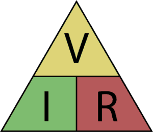
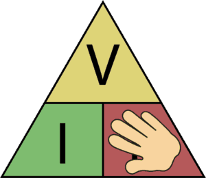
Place your hand across what you want to find, resistance (R), and you’re left with voltage (V) over current (I):

$R_{B} & =\frac{V_{RB}}{I_{B}}=\frac{5V-0.7V}{10\,mA}=430\,\varOmega$

Ohm's law for resistance

Note: A transistor will have current limitations. Many common-purpose transistors will only give you up to 100 mA. So for a current of 1A, it’s important to choose a transistor that can handle it.

The PNP Transistor as a Switch

A PNP transistor works the same way as an NPN transistor for switching operations, but the current flows in the opposite direction.

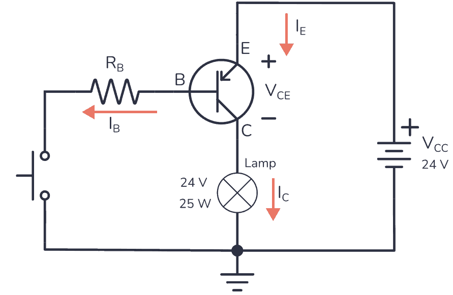
Let’s try to turn on / off the 25 W lamp again using the PNP transistor in its common emitter configuration:

PNP transistor as switch

As you can see above, instead of providing a digital signal to drive the transistor, the circuit now includes a push button. We will learn how to use a digital signal later.

The PNP common-emitter setup may seem weird because the emitter is connected to the positive terminal of the power supply. But since the currents flow in the opposite direction it means the base has to be more negative than the emitter to turn the PNP on.

So the lamp is still connected to the collector, but now it is connected to the negative terminal of the power supply.

PNP transistor as switch gif

When the push button is open, no current flows through the base, which means the transistor is not activated and acts as an open switch, causing the load to be off. But when you press the push button, current flows through the base and the collector, making the transistor act as a closed switch and turning on the lamp.

How to Choose the Base Resistor

The calculations we did for the base resistor of the NPN transistor are more or less the same for the PNP transistor.

For example, if the lamp requires 1 A and you use a transistor with a β of 50, IB would be…

$I_{B}=\frac{1\,A}{50}=0.02\,A=20\,mA$

So, as before, once you have the IB current, you just need to apply Ohm’s law. There is a slight difference from what we did in the NPN transistor, as VRB is the voltage difference between VCC and VBE.

$R_{B} & =\frac{V_{RB}}{I_{B}}=\frac{24V-0.7V}{20\,mA}=1165 \,\varOmega$

PNP Transistor With a Microcontroller

Whenever the voltage at the base of the PNP transistor is below VCC, the transistor would be activated, making it impractical to directly connect a digital signal to the base. To control a PNP transistor with any digital signal, you can use the Sziklai configuration:

PNP Sziklai

MOSFET as a Switch

MOSFET transistors have three legs: Source (S), Gate (G), and Drain (D).

One of the main differences between MOSFETs and BJTs is that BJTs are controlled by the current through the base, while MOSFETs are controlled by the voltage at the gate.

Just as with BJTs, there are two types of MOSFETs, the nMOS and the pMOS. Let’s see how to use them as switches.

nMOS Transistor as a Switch

An nMOS transistor works like this: When a voltage higher than the transistor’s threshold voltage (VTH) is applied between the gate and the source, a current can flow from the drain to the source, making the transistor work as a closed switch.

If 0V is applied to the gate, no current will flow, so the transistor will behave like an open switch.

Let’s try to turn on the lamp:

N Channel Enhancement as switch

In the above circuit, the lamp is connected to the drain and the positive terminal of a DC power supply, and the source is connected to the negative terminal.

When the pushbutton is pressed, the positive voltage between the gate and the source enables current to flow from drain to source, turning on the lamp.

Make sure that the voltage you use for the gate is a bit higher than the voltage threshold (VTH) stated by the manufacturer. For example, the IRF510 MOSFET has a VTH of 2.0V, so you could use 5V without any problems.

N Channel Enhancement as switch gif

In the opposite case, when the pushbutton is open, the lamp will be off because current cannot flow.

You may wonder, and what about RGS? Well, the gate needs a pull-down resistor to ensure transistor deactivation. This is because the gate-to-source part of a MOSFET behaves like a capacitor. So if you leave the gate floating after it has been connected to a voltage, this voltage stays at the gate and keeps the transistor on.

The value of RGS isn’t crucial; a 10 kΩ resistor should work fine.

pMOS Transistor as a Switch

The pMOS transistor works like this: To turn the transistor on, the voltage from source to gate must be higher than the threshold voltage (VTH) of the transistor. This is opposite from the nMOS where it was the voltage from gate to source that had to be higher than VTH.

What you really need to do is ensure that the gate is more negative than the source. For this, you can use the following circuit:

P Channel Enhancement as switch

As you can see in the circuit diagram above, the lamp is now connected to the negative terminal of the DC power supply and to the drain, while the source is connected to the positive terminal.

The gate of the MOSFET is controlled by a switch. When it makes contact with L2, the gate becomes more negative than the source, turning on the lamp.

When the switch makes contact with L1, the voltage between the gate and the source is 0V, which turns off the lamp.

P Channel Enhancement as switch

Do MOSFETs need a gate resistor?

The short answer is no, but it all depends on the application. For example, if you are going to drive an N-channel MOSFET with a microcontroller with output pins that are sensitive to overcurrent, you should use the following circuit:

Mosfet switch with microcontroller

Using a MOSFET with a digital device without a gate resistor will most likely work, but adding one can help prevent potential overcurrent problems. You can learn more about this in our article about the MOSFET gate resistor.

Copyright Build Electronic Circuits

Wednesday, 1 November 2023

Arduino RGB LED Guide: Easy Setup and Code Examples

In this guide, you’ll learn how to control an RGB LED using the Arduino. An RGB (Red-Green-Blue) LED can produce a wide variety of colors by mixing different intensities of red, green, and blue light. You’ll learn to create a basic Arduino RGB LED circuit and cycle through some basic colors as an example.

Using the provided schematic and breadboard images, as well as the example code below, you should have everything you need to easily set up and control an RGB LED’s color output on your own.

Parts Needed

There are two types of RGB LEDs: Common Anode and Common Cathode. We’ll provide example schematics and code for both types below.

How To Connect an RGB LED to an Arduino

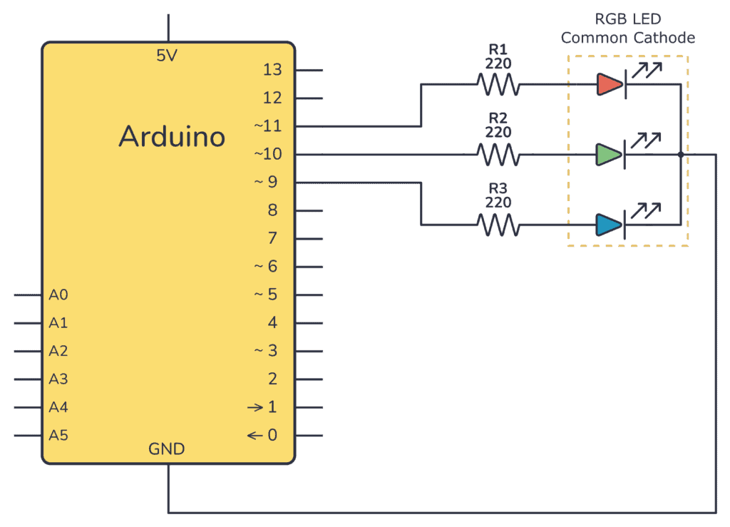
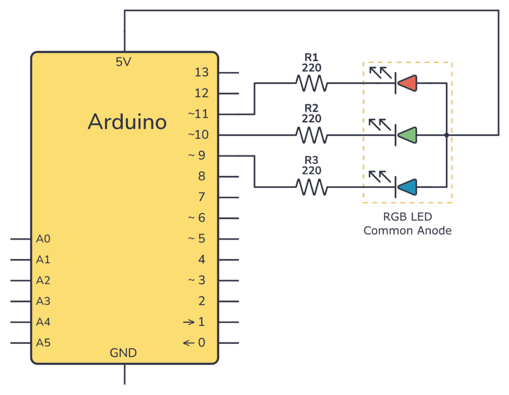
Here’s the schematic for the circuit. This diagram uses three resistors and a common anode RGB LED (you’ll find the schematics for a common cathode below).

Arduino RGB LED schematic for a common cathode type LED

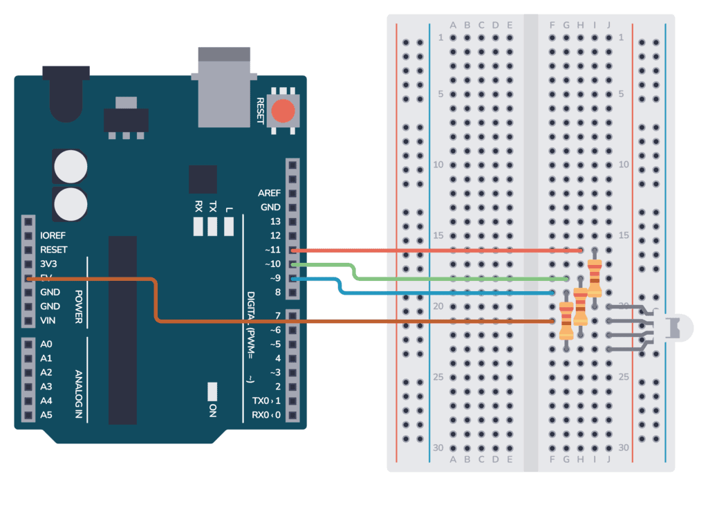
If you’re using a common anode LED, you need to connect the common anode pin to 5V, like this:

Arduino RGB LED schematic for a common anode type LED

Steps To Connect the Circuit on a Breadboard

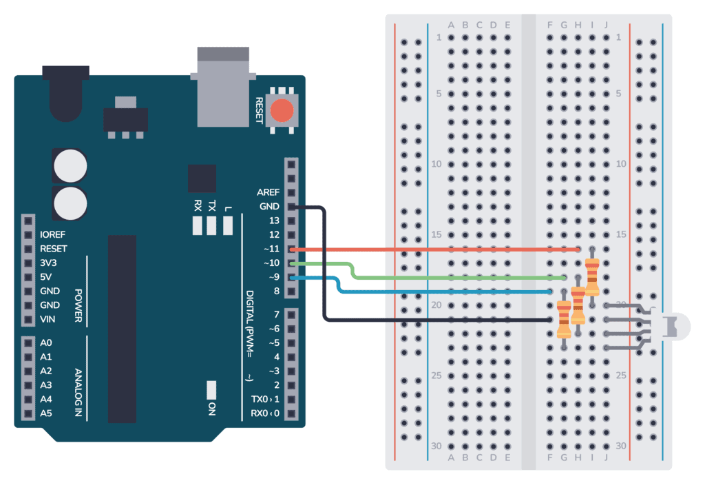
  1. If you’re using a common cathode RGB LED, connect the cathode to the GND pin on the Arduino. If your RGB LED is a common anode, connect the anode to the 5V pin on the Arduino.
  2. Connect the red, green, and blue legs of the LED to pins 11, 10, and 9 of the Arduino respectively, each through a 220-ohm resistor.
  3. Make sure your Arduino is connected to your computer via a USB cable.

Use one of the breadboard images below as a visual guide to set up your connections:

Common Cathode RGB LED connected to an Arduino
Common Cathode RGB LED connected to Arduino
Common Anode RGB LED connected to Arduino

Upload the Arduino RGB LED Code

Upload the code below to your Arduino using the Arduino IDE, and you should see the LED cycle through different colors, stopping for one second on each color.

Complete Arduino code for RGB LED (Common Cathode):

int redPin= 11;
int greenPin = 10;
int bluePin = 9;

void setup() {
  pinMode(redPin, OUTPUT);
  pinMode(greenPin, OUTPUT);
  pinMode(bluePin, OUTPUT);
}

void loop() {
  setColor(255, 0, 0); // Red Color
  delay(1000);
  
  setColor(0, 255, 0); // Green Color
  delay(1000);
  
  setColor(0, 0, 255); // Blue Color
  delay(1000);
  
  setColor(255, 255, 0); // Yellow Color
  delay(1000);

  setColor(0, 255, 255); // Cyan Color
  delay(1000);
  
  setColor(255, 0, 255); // Magenta Color
  delay(1000);
  
  setColor(255, 165, 0); // Orange Color
  delay(1000);
  
  setColor(128, 0, 128); // Purple Color
  delay(1000);
  
  setColor(255, 255, 255); // White Color
  delay(1000);
}

void setColor(int redValue, int greenValue, int blueValue) {
  analogWrite(redPin, redValue);
  analogWrite(greenPin, greenValue);
  analogWrite(bluePin, blueValue);
}

If you’re using a common anode RGB LED, the logic is inverted compared to a common cathode RGB LED. In a common cathode RGB LED, you provide power (HIGH) to a specific pin to turn on a color. For a common anode RGB LED, you ground (LOW) a specific pin to turn on a color.

So, for a common anode RGB LED, to set the color, you need to subtract each color value from the maximum (which is 255) before applying it. This inversion ensures that a value of 255 (full intensity) for a specific color results in that color being turned off, while a value of 0 (no intensity) results in that color being fully on.

Complete Arduino code for RGB LED (Common Anode):

int redPin= 11;
int greenPin = 10;
int bluePin = 9;

void setup() {
  pinMode(redPin, OUTPUT);
  pinMode(greenPin, OUTPUT);
  pinMode(bluePin, OUTPUT);
}

void loop() {
  setColor(255, 0, 0); // Red Color
  delay(1000);
  
  setColor(0, 255, 0); // Green Color
  delay(1000);
  
  setColor(0, 0, 255); // Blue Color
  delay(1000);
  
  setColor(255, 255, 0); // Yellow Color
  delay(1000);

  setColor(0, 255, 255); // Cyan Color
  delay(1000);
  
  setColor(255, 0, 255); // Magenta Color
  delay(1000);
  
  setColor(255, 165, 0); // Orange Color
  delay(1000);
  
  setColor(128, 0, 128); // Purple Color
  delay(1000);
  
  setColor(255, 255, 255); // White Color
  delay(1000);
}

void setColor(int redValue, int greenValue, int blueValue) {
  analogWrite(redPin, 255 - redValue);
  analogWrite(greenPin, 255 - greenValue);
  analogWrite(bluePin, 255 - blueValue);
}

How the Code Works

This code first sets up the RGB-led pins via the variables redPin, greenPin, and bluePin. Change these if you are using different pins than in the example circuit.

Then, the code lights up the RGB LED with the colors red, green, blue, yellow, cyan, magenta, orange, purple, and white, pausing for a second on each color.

Conclusion

Enjoy experimenting with different color combinations by altering the values in the setColor function! Remember, RGB LEDs combine red, green, and blue light to produce a vast array of colors. You’re now equipped to create colorful displays with your Arduino and RGB LED!

Copyright Build Electronic Circuits

Arduino Thermistor Guide: Easy Circuit & Code Walkthrough

In this tutorial, we’ll guide you on how to set up a thermistor with Arduino to create a basic thermometer. The schematic, breadboard illustration, and example code provided will make it easy and straightforward to get your thermistor working.

Parts Needed

Step 1: Understand the Thermistor

Our thermistor has the following parameters:

  • T0: 25°C
  • RT0: 10,000 Ω
  • B: 3977 K

These values are found in the datasheet provided by the thermistor manufacturer. Check out this example datasheet for a thermistor from Vishay.

T0 is the reference temperature of the thermistor. For most thermistors, this is 25°C.

RT0 is the resistance of the thermistor at the reference temperature (which is commonly 25°C).

The B value, also known as the “beta value” or “B coefficient”, of the thermistor gives you insight into how the resistance changes with temperature. You’ll need this value in order to calculate the temperature of the thermistor.

Step 2: Connect the Arduino Thermistor Circuit

To connect a thermistor to an Arduino, connect it in series with a resistor between 5V and GND. Then connect the middle connection between the two to an analog input pin on the Arduino.

Arduino thermistor schematic

Here’s how you can connect a thermistor and resistor to an Arduino by using a breadboard and some cables:

Arduino thermistor circuit connected on a breadboard

Step 3: Upload the Arduino Thermistor Code

This Arduino code shows you how to read the voltage across the thermistor, convert it into resistance, and use that to calculate the temperature around the thermistor.

It then prints out the temperature value in Celcius, Kelvin, and Fahrenheit to the Serial Monitor.

Upload the complete code:

// Thermistor parameters from the datasheet
#define RT0 10000
#define B 3977

// Our series resistor value = 10 kΩ
#define R 10000  

// Variables for calculations
float RT, VR, ln, TX, T0, VRT;

void setup() {
  // Setup serial communication
  Serial.begin(9600);
  // Convert T0 from Celsius to Kelvin
  T0 = 25 + 273.15;
}

void loop() {
  // Read the voltage across the thermistor
  VRT = (5.00 / 1023.00) * analogRead(A0);
  
  // Calculate the voltage across the resistor
  VR = 5.00 - VRT;

  // Calculate resistance of the thermistor
  RT = VRT / (VR / R);
  
  // Calculate temperature from thermistor resistance
  ln = log(RT / RT0);
  TX = (1 / ((ln / B) + (1 / T0)));

  // Convert to Celsius
  TX = TX - 273.15;
  
  Serial.print("Temperature: ");
  // Display in Celsius
  Serial.print(TX);                  
  Serial.print("C\t");
  
  // Convert and display in Kelvin
  Serial.print(TX + 273.15);
  Serial.print("K\t");

  // Convert and display in Fahrenheit
  Serial.print((TX * 1.8) + 32);
  Serial.println("F");
  
  delay(500);
}

Step 4: Monitor the Temperature

Open the Serial Monitor from the Arduino IDE by clicking the magnifying glass icon or using the keyboard shortcut Ctrl + Shift + M (Windows/Linux) or Cmd + Shift + M (Mac). Set the baud rate in the Serial Monitor to 9600 (or the same value as in the Serial.begin() function in the code).

In the serial monitor window, you’ll be able to see the temperature values in Celsius, Kelvin, and Fahrenheit. The values will refresh every 500 milliseconds.

Try heating the thermistor with your fingers to see the temperature change.

Example output to expect in the Serial Monitor:

Temperature: 25.00C   298.15K   77.00F
Temperature: 24.89C   298.04K   76.80F
Temperature: 26.12C   299.27K   79.02F
Temperature: 27.38C   300.53K   81.28F
Temperature: 27.50C   300.65K   81.50F
Temperature: 26.80C   299.95K   80.24F
Temperature: 25.78C   299.93K   78.40F
Temperature: 25.10C   298.25K   77.18F

Conclusion

You’ve successfully set up a thermometer using a thermistor with Arduino! This setup can be integrated into larger projects or used standalone to monitor temperature in any desired setting. Always refer to the thermistor datasheet for any component-specific information. Happy tinkering!

Copyright Build Electronic Circuits

Researchers develop recyclable, healable electronics

Electronics often get thrown away after use because recycling them requires extensive work for little payoff. Researchers have now found a w...