Saturday, 7 April 2018
Creating a 2-D platinum magnet

Friday, 6 April 2018
Why noise can enhance sensitivity to weak signals
Web Controlled Servo using ESP8266
In this ESP8266 WiFi Module based project, we will see about a Web Controlled Servo using ESP8266 where the position of the Servo Motor can be controlled through a Web Page (within the same WiFi Network).
Overview
Servo Motors are one of the most commonly used motors in both industries and DIY Projects. Two of the most famous project involving Servo Motors are our ARDUINO ROBOTIC ARM and DIY BLUETOOTH CONTROLLED 3D PRINTED ROBOTIC ARM.
So, in this project, I’ll demonstrate a Servo Motor based project involving Tower Pro SG90 Servo Motor and ESP8266 WiFi Module.
I’ll be creating a simple Web Page (HTML) with a slider. When this web page is accessed from a computer or mobile phone that is connected to the same WiFi Network as the ESP8266, you can control the position of the Servo Motor by adjusting the slider.
Concept behind Web Controlled Servo using ESP8266
Normally, in order to control a Servo Motor with Arduino (for example), all you need is a Servo Motor, Arduino and a Potentiometer. Depending on the position of the POT, the PWM value of the Servo Motor input changes and consequently the position of the Servo Motor’s shaft changes.
In case of a Web Controlled Servo Motor using ESP8266, Arduino still drives the Servo Motor but the input isn’t from a POT but a Web Page we created.
The slider in the web page sends the angle values and is received by the ESP8266, which acts as a Web Server. The ESP8266, upon receiving the value, transmits it to the Arduino, which then changes the position of the Servo Motor according to the value.
One important thing to remember here is that both the Server and client should be on the same network i.e. the ESP8266, which acts as the Server, and the Computer (or a Mobile Phone), which is the client, must be connected to the same WiFi network.
Prerequisites for Web Controlled Servo using ESP8266
First and important thing is that the ESP8266 Module must be flashed with AT Commands Firmware. For more information on this, please refer HOW TO FLASH UPDATE AT COMMANDS FIRMWARE IN ESP8266.
Second important thing is to control the ESP8266 (that is loaded with AT Commands Firmware) using Arduino. For this project, please refer WIFI CONTROLLED LED USING ESP8266 AND ARDUINO.
Circuit Diagram
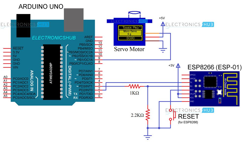
The circuit diagram for Web Controlled Servo using ESP8266 WiFi Module is given in the image below.
Components Required
- Arduino Board (any Arduino)
- ESP8266 based Board (I’ve used ESP-01)
- Tower Pro SG90 Servo Motor
- Jumper Wires
- Resistors (1 KΩ and 2.2 KΩ) – both are ¼ Watt
- Button
- Slide Switch (SPDT)
- Computer (or Mobile Phone)
Design of the Circuit
The main program will be for Arduino and it will be responsible for everything i.e. connecting ESP8266 to WiFi, getting information for ESP8266 and finally controlling the Servo.
In order to enable Serial Communication between Arduino and ESP8266, Pin 2 and 3 of Arduino are enabled as SoftwareSerial (in the program). Here, Pin 2 acts as RX and Pin 3 as TX. So, connect TX of ESP8266 to Pin 2 of Arduino and RX of ESP8266 to Pin 3.
Since, ESP8266 cannot tolerate 5V, the TX of Arduino (pin 3) is first level shifted using two resistors (1 KΩ and 2.2 KΩ) and then connected to RX of ESP8266.
The VCC, CH_PD and GND pins of ESP8266 are connected to 3.3V, 3.3V and GND respectively. The RESET pin of ESP is connected to a button where the other end of the button is connected to GND.
Pin 9 of Arduino will provide the necessary PWM signal to the Servo (Orange). Its other pins are power supply pins and are connected to 5V and GND (Red and Brown).
Code
Arduino Code
The Arduino Code for the Web Controlled Servo using ESP8266 project is given below.
HTML Code for Web Page
In order to create a simple Web Page, I’ve used the following HTML Code.
NOTE: In order to create a Web Page using this HTML Code, save this code with an extension .html in a folder and in the same folder place the “myjquery,js” file which you can download from here.
Working of Web Controlled Servo using ESP8266
Let us now see the working of the Web Controlled Servo using ESP8266 and Arduino. After making all the connections as per the circuit diagram, upload the Arduino code to Arduino UNO.
After the code is uploaded, if you open the serial monitor, you can see the status of the ESP8266 WiFi Module.
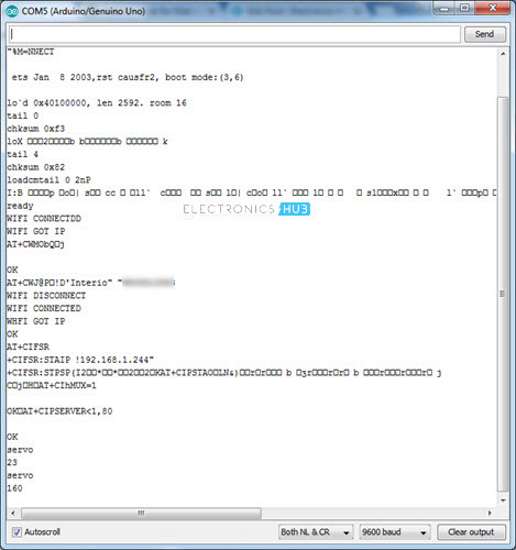
After all the initialization steps are done (set mode to Station mode, connect ESP to WiFi, set static IP and start web server), you can proceed for Web Control.
Now, open the HTML file using any web browser. A simple text indicating the project will be displayed. Below that, you can see a slider.
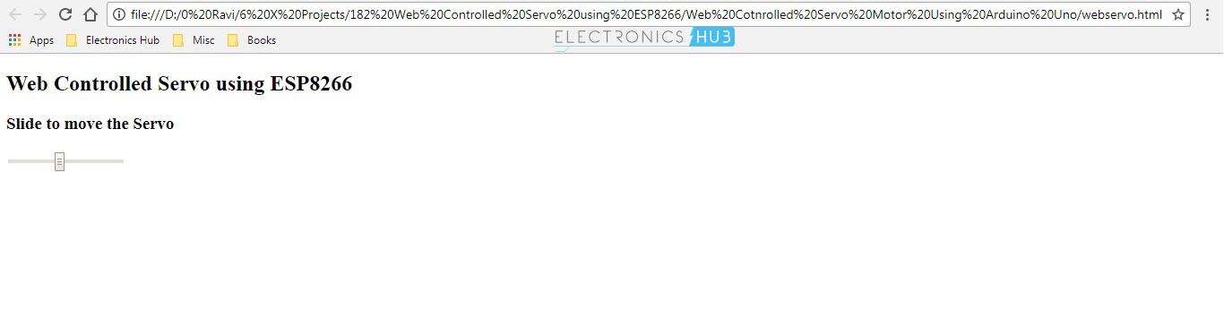
If everything is right, when you change the position of the slider, the position of the servo Motor will be changed.
Applications
The idea behind Web Controlled Servo using ESP8266 is to implement a web-controlled device (in this case, a Servo Motor) i.e. to control a motor through internet.
This application can be further extended to more advanced and complex projects like controlling a Robot from the Internet.
The post Web Controlled Servo using ESP8266 appeared first on Electronics Hub.
Virtual Reality vs Augmented Reality
Virtual Reality and augmented reality have both been buzz words since the last few months of 2017. Both hold tremendous potential for growth in almost all fields. They’re powerful tools that can help us experience reality in a manner that can dramatically shift our perception of the world. However, despite the hype, many people cannot differentiate between virtual reality and augmented reality. How are virtual reality and augmented reality different from each other? Let’s dive right into it. What is Virtual Reality? Virtual reality allows you to escape the real world by blocking out everything in your surroundings and creating a simulation of a new reality. By putting on the VR goggles, the user experiences the simulated reality first hand. Virtual reality can be experienced by using Oculus Rift, Google Cardboard or Samsung Gear VR. By putting on your VR gear, you can instantly get transported into the era of dinosaurs or climb on top of mountains. Once you put your gear on, your immediate vision is blocked out. You will fully and completely get immersed into a new stimulated reality be it nature or fantasy. A coding language known as Virtual Reality Modelling Language (VRML) is used to program images and graphics to allow the users to experience stimulated reality. VR technology stimulates the visual and auditory sensors of the users and it allows them to completely become absorbed in their new stimulating surroundings. Different users have reported different experiences. Most people are completely blown by the experience. However, there are some, who have had problems such as nausea when they’ve tried to use Gear VR. This is mainly because our brains are quite smart and they may recognize discrepancies between our motions and the movement of the world around us. When that happens, our brain questions the reality of the world around us and causes us to feel nauseous. However, VR is still relatively new and it is continuously evolving. Undoubtedly, this problem won’t last for long as new technology emerges. Image Source What is Augmented Reality? Augmented reality enhances the current reality by adding computer-generated elements into it. It “augments” the reality and makes it more meaningful for the users by allowing real-time interaction. Augmented reality is often used on mobile phones via applications that have been programmed to process AR. These apps blend digital elements into the real world to provide more clarity. Many tech giants such as Facebook and Samsung have expressed interest in AR. We will surely be seeing lots of new developments in this field. Difference between virtual reality and augmented reality. Virtual reality and augmented reality differ in terms of the “presence” of the user. In virtual reality, the user is transposed into a virtual world and disconnects with the world around him. Whereas augmented reality just alters the current reality for the user. It helps them add elements into their existing reality without altering their presence in any way. Many people use VR and AR synonymously, but that couldn’t be further from the truth. To understand this concept consider the analogy of a jungle. By using VR, you are a part of the jungle as you explore all its secrets and navigate across the maze. In contrast, in AR you’re like an outside viewer seeing what happens in the jungle. You can even wear AR glasses, and see all the wild animals come to life in your own backyard. Applications of Virtual Reality Virtual reality is a powerful tool. While many people are aware of the exhilarating experience VR provides in gaming, not many know the potential VR holds in other...
read more
The post Virtual Reality vs Augmented Reality appeared first on Electronic Circuits and Diagrams-Electronic Projects and Design.
Thursday, 5 April 2018
Visible Light Communication-History, Working & Applications
Over the few past years, a myriad of technological advancements has been evidenced in the lighting and communication sector. The most amusing one being visible light communication (VLC). Invented in the late in the 18th century, the means has not only undergone numerous advancements but also applied in different sectors. What is Visible Light Communication aka VLC? Visible Light Communication is a communication method where visible light within a particular frequency range is used as the medium of communication. The visible light frequency range for VLC is from 400 to 800 THz. VLC operates under the concept of transmission of data via light rays to send and receive messages in a given distance. Putting to use LED lighting, VLC can be used as a replacement for radio frequencies in areas it cannot be applied. In addition, VLC has the upper hand over radio frequencies as it offers ultra-fast data transmission and also high bandwidth transmission. This has been most evident in traffic lighting, besides other sectors. Being a complex field, it arouses questions on its significance, its operation, and areas in which it is well suited for. History of Visible Light Communication The concept of VLC (visible light communication) dates back as early as 1880 (4 years prior to the invention of radio transmission). This was first put into use by alexander graham bell, a Washington D.C resident when he invented the photophone. The method relayed speech over long distances via modulated sunlight. However, back then the idea was not applied much as it was centuries ahead of its time. Due to this, the technology paved way for slower communication media thus was never a big hit. However, this acted as a guiding line for fiber optic communication that was invented in the 80’s. later in 1995, students of Universidad de Buenos Aires worked on the concept and thus resulted in a laser diode that was used in photodiodes detection. in 2003, three undergraduates from Keio University, Japan, worked more on the concept using LED lighting. Given the presence of sophisticated technology, people were able to manipulate the technology and put it to use. In 2006, CICTR researchers combined LED lighting to power line communication and resulted in a number of indoor applications of VLC. Over the years, the technology underwent a number of researchers and changes and thus leading to various uses inclusive of High definition videos. This technology found its way into the security field, transport sector and even banking sectors between 2010 and 2017. Working – How Visible Light Communication Works? Given that light travels 186,000 miles in a second, communication via this source is virtually instantaneous. This makes VLC the fastest means of communication between all means available in the market. to function, VLC uses visible light between 780 to 375 nm which are visible to the human eye. Every form of data can be broken down into single units of ones and zeroes that can be deciphered as low or high signals. In VLC, this is achieved by fast turning of light on and off (also called on-off keying, OOK). However, this form of data transmission is dependent on how fast the light can go on and off. To achieve great results, LED lighting is well suited for the task as it has a short rise and fall time thus faster switching. Due to this, LED lighting is used in all wireless forms of VLC. To function, VLC requires a receiver (photodetector), a transmitter (LED’s) and a channel of communication. In addition, the circuit features a photodiode, transimpedance amplifiers, auto gain controllers, high pass filters...
read more
The post Visible Light Communication-History, Working & Applications appeared first on Electronic Circuits and Diagrams-Electronic Projects and Design.
Wednesday, 4 April 2018
Pulling valuable metals from e-waste makes financial sense
Breakthrough made in atomically thin magnets
-
CMOS (Complementary Metal Oxide Semiconductor) The main advantage of CMOS over NMOS and BIPOLAR technology is the much smaller power dis...
-
Bluetooth Controlled Electronic Home Appliances is a simple project, where we can control different electrical appliances and electronic de...
-
I was first introduced to logic gates when I was around 14 years old. I had heard that computers consisted of ones and zeroes. But I didn’t...


