Wednesday, 27 June 2018

Arduino Car Reverse Parking Sensor

In this project, I will design a simple Arduino Car Reverse Parking Sensor Circuit using Arduino UNO and HC-SR04 Ultrasonic Sensor. This Arduino based Car Reverse Sensor can be used for an Autonomous Navigation, Robot Ranging and other range related applications.

Overview of Arduino Car Reverse Parking Sensor

Parking a car in congested parking lots and tiny spaces is a tedious job and the important thing is that you must be very careful while reversing so that you do not damage the car (your car or the adjacent one).

Almost all modern cars are equipped with reverse parking sensors that are activated when the car is put in reverse gear and beep at variable rate depending on the distance between the car and the closest obstacle.

The Reverse Parking Sensors that are equipped in the car are basically Ultrasonic Proximity Sensors i.e. they use Ultrasonic Sensors to measure the distance between the car and the object and warn the driver if the car is too close.

In this project, I have built a simple prototype of a Car Reverse Parking Sensor with the help of Arduino UNO and the very famous HC-SR04 Ultrasonic Sensor.
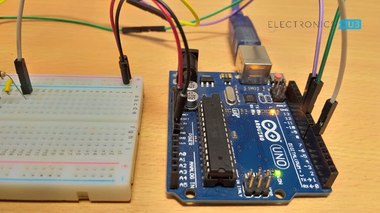
Arduino Car Reverse Parking Sensor Arduino

Although this system can be implemented in several DiY projects involving robots, autonomous vehicles etc., I wouldn’t recommend it to actually implement in your car (if your car isn’t already equipped with one).

Circuit Diagram

The circuit diagram of Arduino Car Reverse Parking Sensor circuit is given in the image below.
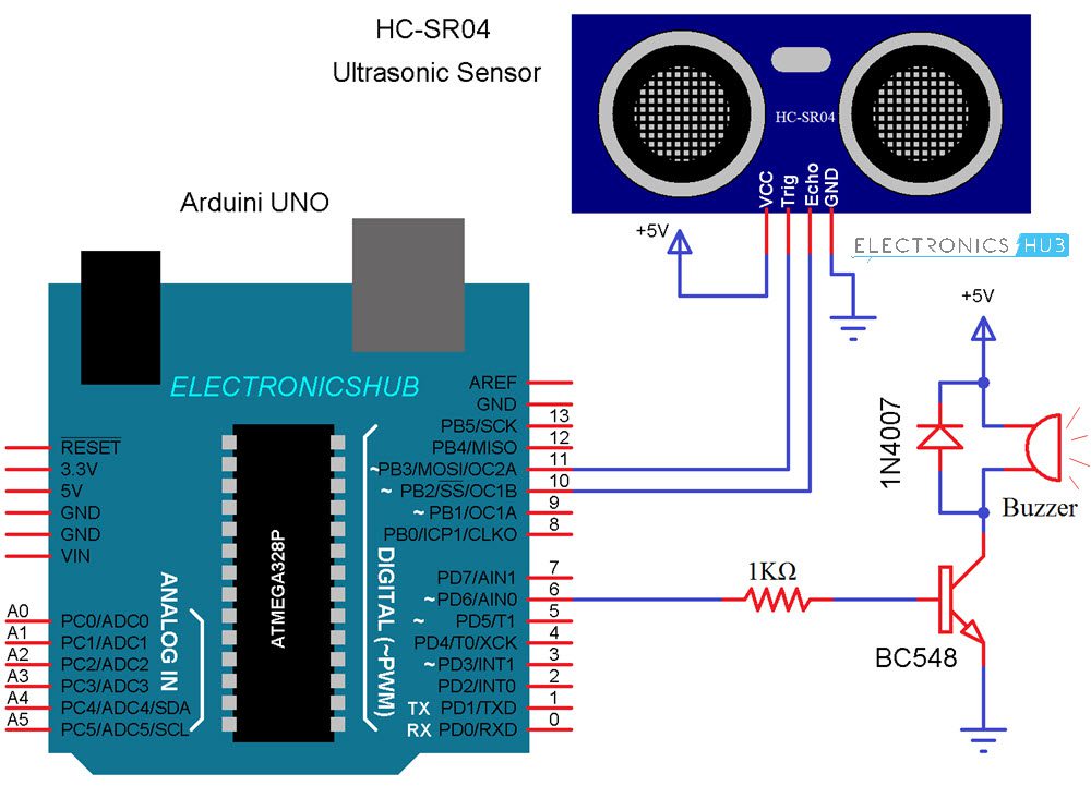
Arduino Car Reverse Parking Sensor Circuit Diagram

Components Required

  • Arduino UNO
  • HC-SR04 Ultrasonic Sensor
  • BC548 NPN Transistor (any NPN Transistor can be used)
  • 5V Buzzer
  • 1N4007 PN Junction Diode
  • 1KΩ Resistor (1/4 Watt)
  • Mini Breadboard
  • Connecting Wires
  • 5V Power Supply

Principle of the Circuit

As mentioned earlier, the Ultrasonic Sensor is the main unit (component) that is responsible for measuring the distance. Arduino UNO acts as the main controlling unit that will control the Ultrasonic Sensor, calculate the distance and activate the buzzer.

The principle of the circuit is as follows: The Ultrasonic Sensor sends acoustic pulses and the Arduino measures the interval of each reflected signal. Based on this time interval, Arduino then calculates the distance of the object.

Arduino then activates the Buzzer if the distance between the sensor and object is less that a certain range.
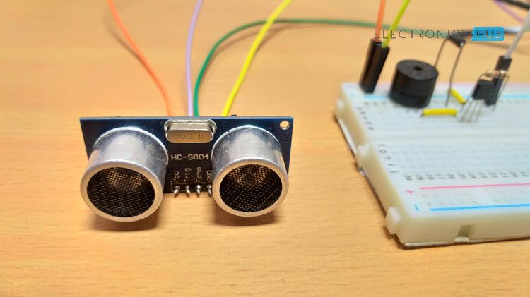
Arduino Car Reverse Parking Sensor Ultrasonic Sensor

Design of Arduino Car Reverse Parking Sensor Circuit

The design of the Arduino Car Reverse Parking Sensor Circuit is very simple. Starting with the Ultrasonic Sensor, it has 4 pins: VCC, TRIG, ECHO and GND.

The VCC and GND are connected to +5V and GND of the power supply while the TRIG and ECHO are connected to Digital I/O pins 11 and 10 of Arduino respectively.

Even though the buzzer used here is a 5V buzzer, I decided to use a driver circuit for the buzzer consisting of an NPN Transistor. I have used BC548 along with a 1KΩ Resistor (for the base) to drive the buzzer.
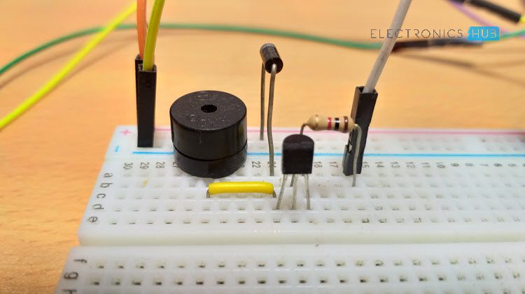
Arduino Car Reverse Parking Sensor Buzzer

Code

The Arduino code for the project is given below.

Code Explanation

The code is very simple and if have followed our PORTABLE ULTRASONIC RANGE METER project, then you can easily understand this code as well.

As per the data sheet of the HC-SR04 Ultrasonic Sensor, its working is as follows:

The TRIG Pin should be high for a minimum of 10µS.

After this, the Ultrasonic Sensor automatically sends 8 acoustic pulses of 40KHz frequency.

The time between this and the reflected signal is calculated by reading the HIGH on the ECHO pin.

Distance can be calculated as Time (for which ECHO is HIGH) * Velocity of Sound (340m/s) / 2.

Using the same principle in the code, first the TRIG is made HIGH for 10µS using the following lines of code.

digitalWrite(trigPin, LOW);

delayMicroseconds(2);

digitalWrite(trigPin, HIGH);

delayMicroseconds(10);

digitalWrite(trigPin, LOW);

Then, the time is calculated for which the ECHO Pin is HIGH using the pulseIn function of Arduino.

duration = pulseIn(echoPin, HIGH);

Finally, the distance in centimeters is calculated using the following line in the code.

distance = 0.034*(duration/2);

Working

I think the working of the project might have been very clear by now. When the circuit is powered ON, the Arduino will start measuring the distance of the objects in front of the Ultrasonic Sensor.

If the calculated distance is less than 100cm, then Arduino activates the buzzer. If you are interested, you can modify the code to beep the buzzer so that the intensity of the beeps increases with a decrease in the distance (like in a real car).  

Applications

The Arduino Car Reversing Parking Sensor Circuit can be used:

  • Autonomous Vehicles
  • Obstacle Avoiding Robots
  • Distance Measurement
  • Proximity Detection
  • Human Detection
  • Drones, UAVs and Helicopters

The post Arduino Car Reverse Parking Sensor appeared first on Electronics Hub.

Tuesday, 26 June 2018

The World’s first robotic kitchen is set for launch in 2018

Robots are not new. We’ve been using them for a multitude of tasks for decades. Any modern manufacturing or processing plant or factory uses robots in some way or ways. Manufacturers know that to stay competitive, you need to cuts costs and improve efficiency in your production line. Robots are the perfect solution. We have used robots in the home environment for some time too. Robotic vacuum cleaners have been on the market for many years. They are programmed to clean and clean they do. But now in 2018, Moley, a London based robotics company has brought all the technology and engineering brilliance of robots into one package to produce the first all robotic kitchen. It’s already been tested in the Robotics Show in Hannover Messe. Reviews have been overwhelmingly positive. The three major talking points are as follows. It works really well It looks fantastic It links up with other state of the art ideas An example of the third point is that iTunes has a wealth of recipes available and these link up with the marvellous robotic kitchen. When you have technology brilliance and team that with a vast supply of online recipes, you create the perfect kitchen experience. Bring the super chefs to your place It seems incredible but it’s true. Think of some of the world’s best and best-known chefs. Think of the great recipes they have created. In fact choose 100 of these stunning meals. Now sit and prepare to dine on the best of the best because the Moley robotic kitchen is fully-automated. It does the lot just as the super chefs would do. But that’s not all. Once your robotic kitchen has produced a magnificent meal, it cleans up afterwards. That surely is an example of a total package. You control the recipe choice but after that the robotic kitchen prepares and cooks the meal and then cleans everything afterwards. So how does it work?  You, the human in the equation, actually have to do something. You must choose the following: How many people are being catered for Which recipe would you like? Place the already prepared food items in the right spot Hit START It’s that easy. The “brains” of the robot has received the information and the ingredients you’ve chosen and the rest is done automatically. Moley Robotics are not just the inventor and creator of the robotic kitchen, they are also the suppliers of the recipes and the ingredients which are part of each recipe. They’ve thought of everything. But there’s much more. What if you’re on a diet? What if you want a cooking style of a particular chef? What if you’re counting calories? Never fear because the intelligence of the AI (Artificial Intelligence) can sort out your requirements for you. Feed in the relevant data and the robots do the rest. What do you get? You don’t need anything else. The robotic kitchen comes with everything including the cooking apparatus, the utensils, the appliances and even the kitchen cabinets. No need for the kitchen sink – that comes as well. The company is working on an in-built cleaning process so all the bench tops, cooking equipment as well as the utensils are cleaned perfectly once they have been used. Tricky becomes easy Top chefs have provided some of their best recipes. Several dishes are difficult if not very difficult to make. The creative chefs talk about the amount of time and effort it takes to get the particular dish just right. Not a problem for the robotic kitchen. It out chefs the chefs. The inspiration The creator, Moley founder...
read more

The post The World’s first robotic kitchen is set for launch in 2018 appeared first on Electronic Circuits and Diagrams-Electronic Projects and Design.

Monday, 25 June 2018

Top 20 electronics companies in India every fresher should know of

One of the most important components of the growth of the economy in India is the electronics industry. There is a massive need for products produced by electronics companies. There is an enormous growth in the many research and development departments seeking to create new and better performing electronic products. Millions of people are employed in one of the many electronics companies operating in India. Offering jobs to electronics engineering students is vital for the individual’s success and in turn for the nation’s prosperity. Here is a description of 20 of the top companies in India which offer employment and produce goods which are used throughout the country. Further details of the history and current status of these companies can be found online. Simply check their web site for further information. The following list does not classify companies in any order. Each listed company has been a successful business for many years in India and all have something to offer. Some have offices in other countries and therefore if international travel or even travel within India appeals, then checking the location or locations of your employment will be a factor. Remember that electronics in a nuclear power plant will require a vastly different set of tools than when working for an electronics company which concentrates on the automobile and LED lighting. From your list of required qualities about your job situation, find those companies which best meet your employment needs. And remember too that while there are 20 electronics companies listed and described in this article, India has many more companies which are involved with the creation, manufacture or distribution in the world of electronics. Top electronics companies in India #1 Havells India Ltd This one is easily recognised because of its growth and value. The company has made spectacular progress in recent times and is currently listed as a billion dollar operation. The areas in which Havells is an expert is that of the production of power distribution equipment. As you can appreciate, once power is generated, being able to distribute it throughout the country is a key installation. Havells have a strong work history in this field. These are generally large projects so if working projects on a grand scale appeals, this is a company worth investigating. #2 Aar em Electronics This company is also known as Champion UPS which is an acronym for Uninterruptible Power Supplies. The company began in 1989 and has been manufacturing power related electronics systems throughout this time. Any company which uses a powerful word like uninterrupted as part of its name is obviously a company with high and exacting standards. #3 Bajaj Electronics This company has been in business for more than 70 years and is now one of the biggest companies with the most popular brands in all of India. The size of the company is impressive with about 20 offices in different parts of the country. It specializes in half a dozen specific areas, viz. Fans, Lights, Luminaries, Appliances as well as Engineering and Projects. Looking at a greener planet, the company has developed use of power saving lights. The sheer size of this company should appeal to potential employees simply because it is so large. But do not make the mistake of under preparing. Make sure your application and presentation (if you get the opportunity) is first class. Plenty of employee opportunities – certainly – but also plenty of applicants just like yourself. #4 Midas Communication Technologies They are the leading provider of wireless services in India. It has been a leading player in this field for many years....
read more

The post Top 20 electronics companies in India every fresher should know of appeared first on Electronic Circuits and Diagrams-Electronic Projects and Design.

How to Send an Email using ESP8266 WiFi Module?

In this project, I will show you how to Send an Email using ESP8266. For this project, I will be using the DFRobot FireBeetle ESP8266 IoT Board. Sending an e-mail with the help of the ESP8266 Module will be a step forward in the IoT Implementation.

Introduction

With Internet of Things (IoT) expanding, the scope of the IoT applications is growing from controlling appliances to monitoring devices (like sensors) and sending e-mails.

By sending e-mails from you ESP8266 Module, you can know the status of any sensor you are monitoring or you can receive an emergency e-mail in case of burglary or an intruder alert.

So, without further delay, let me show you all the steps required to Send an Email using ESP8266 WiFi Module.

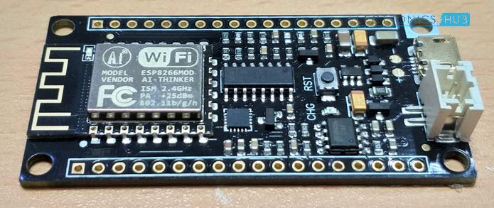
ESP8266 Board

As said earlier, I will be using the DFRobot FireBeetle ESP8266 board in this project to send e-mails. You can use any ESP8266 Module and I have tested this procedure with my ESP-01 ESP8266 Board and it worked just fine.

DFRobot FireBeetle ESP8266 Review FireBeetle

Since the DFRobot FireBeetle ESP8266 board has all the required components like the MicroUSB Port, 3.3V Regulator, etc. I don’t need to make any extra connections with respect to the board.

All I need to do is to plug-in a MicroUSB cable in the port and connect it to a computer (with the drivers being already installed and Arduino IDE is already setup).

This is one of the main reasons for choosing the DFRobot FireBeetle ESP8266 board over my regular ESP-01 Module.

So, I suggest you to go through the hook-up guide of the DFRobot FireBeetle ESP8266 board as described in the following project: DFROBOT FIREBEETLE ESP8266 REVIEW AND HOOK-UP GUIDE.

SMTP Server Setup

In order to send e-mails from ESP8266 Module, you need to follow the SMTP protocol. Hence, an SMTP Server is required to send the e-mails and the ESP8266 will act as an SMTP Client.

I have tried the Gmail’s SMTP Settings several times to send email using ESP8266 but it was not fruitful. So, I have decided to use a third-party SMTP Server and I found “SMTP2GO” as a reliable choice.

Send an Email using ESP8266 SMTP2GO Home

So, go to the SMTP2GO website and register with a free account. After creating an account, the first step is to create the SMTP Username and SMTP Password. In fact, the moment you confirm your e-mail address and first login to SMTP2GO, this is the information that you’ll get.

Leave the username as it is i.e. the e-mail address and change the SMTP Password with your own choice. Note that this is SMTP Password and is different from the SMTP2GO Login Password.

Make a note of the two i.e. SMTP Username and SMTP Password.  

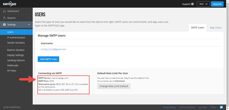
Now, enter the dashboard of the SMTP2GO app and on the left access bar, click on “Settings” and then on “Users”.

In that, you can see the information regarding the SMTP Server and PORT number. It is usually as follows:

  • SMTP Server: mail.smtp2go.com
  • SMTP PORT: 2525

Send an Email using ESP8266 SMTP2GO Server

Note down this information as you need to use this data in the code.

Encoding Username and Password

You need to encode your SMTP Username and SMTP Password to Base64 format with ASCII Character Set. For this, you can either use an Arduino Library or a website called BASE64ENCODE.

Send an Email using ESP8266 Base64 Encode

Enter your SMTP Username and Password separately and note the encoded content. For example, if your email address is test@gmail.com, it would be encoded as dGVzdEBnbWFpbC5jb20=.

And if your password is “testpassword” (excluding the quotes), it would be encoded as dGVzdHBhc3N3b3Jk.  

Code

Now, let me show you the necessary code in order to Send an Email using ESP8266.

In the code, make necessary changes like SSID, Password of your WiFi Connection, Sender and Receiver E-Mail Address, Base64 Encoded SMTP Username and SMTP Password.

Explanation of the Code

The initial section of the code is simple used to connect the ESP8266 WiFi Module to the Internet. If the connection is successful, you will get an IP Address.

Next is the actual code for sending the e-mail. The code can be divided into 8 stages.

Stage 1: In stage 1, you will be connecting to the SMTP Server on a PORT. This is done using the command client.connect(SMTP_SERVER, SMTP_PORT). In response, you will get a 220 code.

Stage 2: Greet the SMTP Server with EHLO Command (Previously HELO Command). The command is client.println(“EHLO www.example.com”);

If the connection is successful, you will get a 250 Response Code.

Stage 3: Stage 3 is to authorize the user with AUTH LOGIN Command. The command is client.println(“AUTH LOGIN”);. You will get a Response 334 for success.

Stage 4: Send the encoded SMTP Username and Password one after the other. The commands are client.println(“Base64, ASCII encoded username”); and client.println(“Base64, ASCII encoded password”);.

If the authentication is success, you will get a 235 Response.

Stage 5: Now its time to send the mail from string where you have to enter the sender’s email address using the format MAIL FROM:<”+String(from)+’>’;.

The command is client.println(“MAIL From: sender@gmail.com”);

Stage 6: Then send the rcpt to string using the format RCPT TO:<”+String(to)+’>’;. The command is client.println(“RCPT To: receiver@gmail.com”);.

Stage 7: Send the “DATA” followed by the Message body of the e-mail. The commands are

client.println(“DATA”);

client.println(“To:  receiver@gmail.com”);

client.println(“From: sender@gmail.com”);

client.println(“Subject: ESP8266 test e-mail\r\n”);

client.println(“This is is a test e-mail sent from ESP8266.\n”);

client.println(“Second line of the test e-mail.”);   

stage 8: Finally, terminate the mail with “.” and send the quit command.

client.println(“.”);

client.println(“QUIT”);

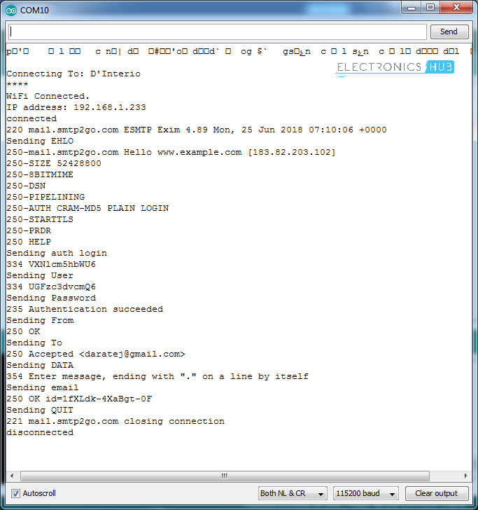
All these commands and responses will be shown in the serial monitor of the Arduino IDE.

Send an Email using ESP8266 Output

If you follow all the mentioned steps, you will be able send an email using ESP8266 successfully.       


The post How to Send an Email using ESP8266 WiFi Module? appeared first on Electronics Hub.

Tuesday, 19 June 2018

Spintronics: Controlling magnetic spin with electric fields

Physicists have found a way to reverse electron spins using electric fields for the first time, paving the way for programmable spintronics technologies.

Best soldering iron kits for every electronic enthusiast

Best 4 soldering kits we selected-Detailed Review 1. AmiciKart’s 60W Soldering Iron Kit If you’re looking for a powerful soldering iron toolset with adjustable temperature control features- Amicikart’s 60W soldering iron kit can be your best bet. The iron is small, compact, lightweight and perfectly suitable for your day-to-day operations. And that’s not all! It also features a super long, 1.5 meter power cable that has an ergonomic 13 cm handle. The handle offers decent grip and lets you get your job done faster.  When you start using the product, you’ll love the ultra-fast heating system that can charge stuff up to 60W within a couple of seconds. The kit comes with a de-soldering pump, a soldering wire of 60/40 inches (weighing around 20 gms), a stand for the soldering iron and a pair of tweezers. You’ll also find bits available in multiple shapes that are designed to make your soldering operations easier. The overall package is an excellent one, and going by its features and tweaks- the product is definitely worth your money. Pros Temperature can be easily adjusted between 200-450 degrees. Comes with a pre-defined dial on the handle which makes it easier to adjust temperature. Lightweight and easy to operate. The power cable has decent length and the handle offers comfortable grip. Comes with a de-soldering pump, a wire for soldering, an iron stand and a pair of tweezers. Cons The pins might burn off faster than you’d expect. Check price & details of this soldering kit   2. Thermisto Electric Soldering Iron Kit The Thermisto Electric Soldering Iron Kit is an excellent device that ensures super-fast operations. Available at a power function of 25 Watts, this kit is ideal for low to medium level soldering. You can easily conduct your small PCB works with this kit. Although the iron isn’t backed by temperature control features, the kit comes with quite a few handy tools, like a soldering wire, wax, device for holding the soldering iron, equipment for stripping wire, pump for de-soldering, tweezers, and de-solwick. You’ll also find quite a few pointed bits that’ll simplify your soldering operations. While the kit does come with quite a few features, we loved the chrome and powder coated soldering stand. This stand is not just powerful, but it also looks great. The product also comes with a 30-day warranty. This means, you can always get back to the manufacturer if you’re dissatisfied with its performance. The overall features are pretty decent, and going by its efficiency- we’d definitely recommend it to everyone who’s looking for a high-quality soldering kit. Pros 25W power helps you with small to moderate soldering jobs. Comes with a thirty day guarantee. Features every additional tool that you’d need. Comes with an extra pointed bit. Soldering stand is pretty sleek. Cons Certain users experienced minor issues as the kit doesn’t come with soldering paste. Check Price & Details of this soldering kit   3. Soldron 25 Watt Soldering Iron Kit If you’re looking for a soldering iron kit for light to moderate soldering jobs- this 25 watt kit from Soldron is an excellent option. Being small and compact, you can always use it for intricate soldering works and since it’s easy to operate, you can get your job done in a jiffy. The kit features almost every nifty tool you’d need for your soldering operations. All you have to do is follow the instruction manual and use them accordingly. Like most of the products listed here, this kit too comes with small tips that can be easily inserted in the iron. Being slide-on and replaceable,...
read more

The post Best soldering iron kits for every electronic enthusiast appeared first on Electronic Circuits and Diagrams-Electronic Projects and Design.

Monday, 18 June 2018

Arduino Lilypad Controlled NeoPixel Earrings

Don’t you want to have such a nice and cool earring when you go out at night or for parties? I would like to have it, that’s why I made Arduino Lilypad Controlled Neopixel Earrings. 🙂 These earrings don’t just light up. They have several different animations and colors.

Arduino Lilypad Controlled NeoPixel Earrings Image 1

Required Materials

Arduino Lilypad Controlled NeoPixel Earrings Image 2

  • Arduino Lilypad (x1)
  • NeoPixel Ring – 12: (x1)
  • USB Serial Converter(x1)
  • 3.7V Lipo Battery (x1)
  • USB Mini-B Cable (x1)
  • JST 2-Pin Battery Connector Plug Female – Male (x1)
  • Female/Female Jumper Wires (x6)
  • Earring Hooks

Circuit Diagram

Arduino Lilypad Controlled NeoPixel Earrings Image 3

Arduino Lilypad Controlled NeoPixel Earrings Image 4

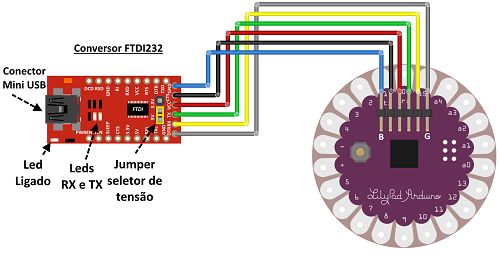
We will start the project by loading code into Lilypad first. In order to program the card, we need a Female/Female Jumper Cable and a USB Serial Converter. After installing the code, we will not have any work with USB Serial.

Make the connection between Lilypad and the USB Serial Converter, as in the picture.

Then, connect the Lilypad with your computer using Micro USB.

Programming the Arduino Lilypad

Arduino Lilypad Controlled NeoPixel Earrings Image 5

Open the Arduino software. Under Tools-Boards, select the Lilypad main board. You need to make sure that the correct board is selected.
Select your port number. It might be a different port for you.

Upload the code to Lilypad main board.

You can copy the Neopixel code from Adafruit’s Github page. Here is the link: NeopixelEarring.

Create a new project in the Arduino IDE. Copy the whole code and paste the code you copied here. Then click the “Upload” button and upload the code to Lilypad.

**If you don’t work with Adafruit libraries before, you might need to add up the Adafruit libraries.

The code loading process is over, no more work with USB Serial Converter.

Neopixel and Lilypad Connection

Arduino Lilypad Controlled NeoPixel Earrings Image 6

It’s time to make the Lilypad and Neopixel connection.

First, we are wiring our cables to the GND, 5V and Input inputs on the Neopixel. Then we will combine this with Lilypad.
The earring will be like this: We’ll make connections to the Neopixel ring with Lilypad on it. After soldering, the wires will leave some space between Lilypad and Neopixel. So you do not have to worry about the connections.

The NeoPixel-Lilypad connection looks like this:

Arduino Lilypad Controlled NeoPixel Earrings Image 7

The Neopixel Ring’s Data In pin will be soldered to the Lilypad’s D6 pin, GND’s to the (-) and 5V’s to the (+) of the Lilypad.

Lipo Battery and Arduino Lilypad Connection

Arduino Lilypad Controlled NeoPixel Earrings Image 8

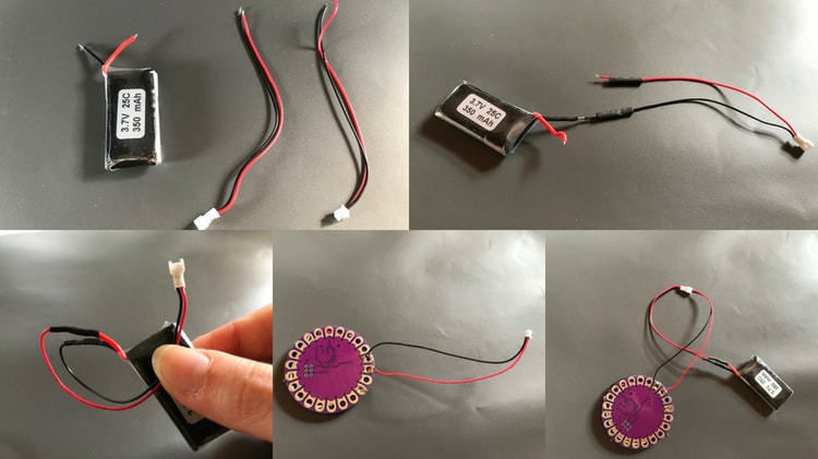
I used these because I had these Lipo batteries. But, smaller Lipo batteries are available. You can also apply a smaller Lipo batteries to the process described below.

In this section, we will perform a small operation of the Lipo battery 🙂

Cut off the tip of Lipo battery. JST 2-Pin Battery Connector Plug Male’s red wire to the Lipo battery’s red wire, soldering the black wire to the Lipo’s black wire.

JST Lipo Battery Connector Plug Female’s red wire to the Lilypad’s (+), soldering the black wire to the Lilypad’s (-)

The final state will look like the picture above. If you connect the LilyPad to the Lipo Battery, Neopixels will start giving light for the LilyPad is powered. Because we loaded the code in the first place.

Seam Neopixel With Lilypad

Arduino Lilypad Controlled NeoPixel Earrings Image 9

I sew NeoPixel and Lilypad together using needles and rope from 3 different places. There are enough holes in both. You can get out of there from anywhere.

Then, stick the Lipo Battery with a double-sided tape on the back of the Lilypad.

Finally, you can cover up the connections with the electrical tape or silicon.

Tighten Earring Clips

Arduino Lilypad Controlled NeoPixel Earrings Image 10

It’s all set. Finally, let’s put the Earring Clip on one of Lilypad’s holes.

And our earrings is ready ! We’re ready for the party. Neopixel are working great !

Good fun with your earrings. 🙂

I expect your comments for the project. You can comment your questions.

Project submitted by Hilal Gungor

Output Video

The post Arduino Lilypad Controlled NeoPixel Earrings appeared first on Electronics Hub.
Researchers develop recyclable, healable electronics

Electronics often get thrown away after use because recycling them requires extensive work for little payoff. Researchers have now found a w...