Monday, 30 January 2023
Superconductivity switches on and off in 'magic-angle' graphene
Powering wearable technology with MXene textile supercapacitor 'patch'
Saturday, 28 January 2023
Transistors repurposed as microchip 'clock' address supply chain weakness
Wednesday, 25 January 2023
The T Flip-Flop (Quickstart Tutorial)
The T Flip-Flop is a flip-flop that can toggle its output. Toggling means switching its output to its opposite; 1 becomes 0, and 0 becomes 1. This type of flip-flop is often used in counters and frequency dividers.
In this quickstart tutorial, you will learn how it works, its truth table, and how to build one.
What is a T Flip-Flop?
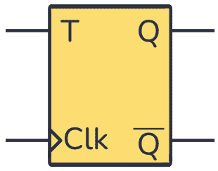
Flip-flops are components commonly used to store a digital value on their output. They have a Clock (Clk) input that decides when to update their output.
The T Flip-Flop is a single-input flip-flop that either holds or toggles its output value.
Toggling, which is the reason for the “T” in the name, means changing between two states. If the output is 1, toggling will change the output to 0. If the output is 0, toggling will change the output to 1.
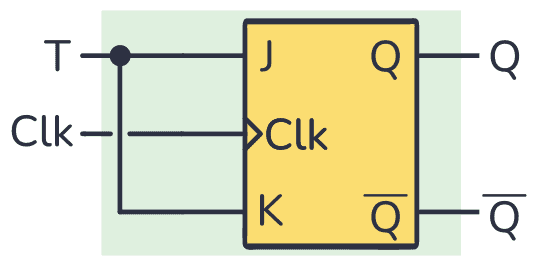
You can build a T Flip-Flop from other flip-flops, for example by using the JK flip-flop and connecting the J and K inputs as follows:
Truth table
In general, you can trigger T Flip-Flops with a falling edge signal, which is the change from a digital state of 0 to 1 ↓, or with a rising edge signal, a change from 1 to 0 ↑. The following truth table corresponds to a flip-flop that triggers on the rising edge:
| Clk | T | Previous Q | Next Q | Description |
|---|---|---|---|---|
| 0 or 1 | X | Q | Q | No rising edge no change |
| 0→1 (↑) | 0 | Q | Q | Memory (no change) |
| 0→1 (↑) | 1 | 0 | 1 | Toggle |
| 0→1 (↑) | 1 | 1 | 0 | Toggle |
You can see that if there is no rising edge in the Clk input, no matter what you put into the T input, the Q output will remain unchanged.
Something like the previous case happens when you have a 0 in the T input. Even if the flip-flop is triggered, if you have either 0 or 1 in the Q output it will stay that way.
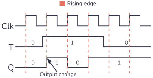
To get the Toggling behavior you have to place a 1 in the T input. What you will observe is a change from 0 to 1 or from 1 to 0 every time the flip-flop is triggered. You can see this behavior in the timing diagram below:
Building a T Flip-Flop Circuit
You can build a T Flip-Flop just by shorting the J and K inputs of a JK flip-flop. However, some websites out there suggest you build the circuit like below. But this is an incomplete circuit that will not work properly:
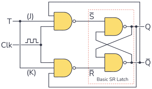
On paper, it seems to work. But what most websites that publish this circuit fail to mention is that you need a very short clock pulse for it to work.
Your clock pulse needs to go high, then low again before the output (Q) changes state. Otherwise, the Q output will toggle quickly between 1 and 0 during the entire positive pulse duration. You can see this behavior in the following timing diagram:
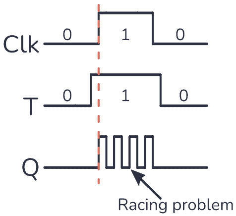
This is a problem called Racing. But it’s easily solved by using an edge-triggered JK Flip-Flop instead.
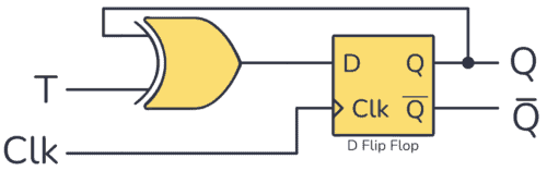
You can also build a fully functional T Flip-Flop by using a D Flip-Flop combined with an XOR gate, like this:
Example Circuit: Toggling an LED
As a practical example, you can toggle a light-emitting diode (LED) using just one push button, the T Flip-Flop, and some resistors. Check out the circuit below:
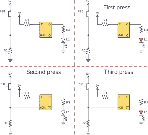
You can see how the T input is connected to 5V, which means logic 1. So every time you trigger the T Flip-Flop, the Q output will toggle its state.
The Clk input uses a pulldown resistor configuration, which means that the Clk input is 0 whenever the button is not pushed. When you press the button PB1, the Clk input will go from 0 to 1 (rising edge signal).
So every time PB1 is pushed, the LED connected to the output Q turns on or off.
To assemble the above circuit you need:
- 1x T Flip-Flop circuit (ex by combining a CD4013 and a CD4030)
- 2x 10 kΩ resistor (R1 and R2)
- 1x 330 Ω resistor (R3)
- 1x Pushbutton
- 1x LED
Questions?
Do you have any questions about this component? Let me know in the comments below and I’ll get back to you as soon as possible.
Copyright Build Electronic Circuits
Tuesday, 24 January 2023
Spin transport measured through molecular films now long enough to develop spintronic devices
Friday, 20 January 2023
Two technical breakthroughs make high-quality 2D materials possible
Thursday, 19 January 2023
Polysulfates could find wide use in high-performance electronics components
-
Do you need a MOSFET gate resistor? What value should it be? And should it go before or after the pulldown resistor? If you’re a bit impati...
-
I was first introduced to logic gates when I was around 14 years old. I had heard that computers consisted of ones and zeroes. But I didn’t...
-
CMOS (Complementary Metal Oxide Semiconductor) The main advantage of CMOS over NMOS and BIPOLAR technology is the much smaller power dis...


