Introduction
In this project, I will show you how to design a simple Radar Application using Arduino and Processing. This Arduino Radar Project is implemented with the help of Processing Application.
Radar is a long-range object detection system that uses radio waves to establish certain parameters of an object like its range, speed and position. Radar technology is used in aircrafts, missiles, marine, weather predictions and automobiles.
Even though the title says Arduino Radar Project, technically the project is based on Sonar technology as I will be using an Ultrasonic Sensor to determine the presence of any object in a particular range.
Project Overview
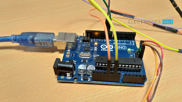
The Arduino Radar Project is more of a visual project than it is a circuit implementation. Of course, I will be using different hardware like Arduino UNO, HC-SR04 Ultrasonic Sensor and a Servo Motor but the main aspect is the visual representation in the Processing Application.
If you remember, I have already used the Processing Application in one of the earlier Arduino Projects involving MPU-6050 Sensor. I suggest you to take a look at that project before proceeding (you don’t have to actually implement the project but understand the way it is implemented).
Reference: GETTING STARTED WITH ARDUINO AND MPU6050
In the MPU-6050 Project, I have used Arduino to read the data from the MPU-6050 Sensor and send it to Processing Application through the COM Port (Serial Communication).
Based on the information received, a sketch in Processing will change the orientation of the model aircraft.
Taking the same concept here, I will collect the information from the Ultrasonic Sensor with the help of Arduino and pass it to Processing where a simple Graphics application is implemented to mimic a Radar Screen.
Circuit Diagram of Arduino Radar Project
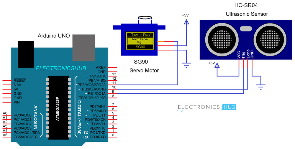
The circuit diagram of this Radar Project is very simple as it involves very little hardware.
Components Required
Hardware
- Arduino UNO
- HC-SR04 Ultrasonic Sensor
- TowerPro SG90 Servo Motor
- Mounting Bracket for Ultrasonic Sensor (optional)
- Connecting Wires
- Jumper Cables
- 5V Power Supply
- USB Cable (for Arduino)
Software
- Arduino IDE
- Processing Application
Circuit Design
If you look at the circuit diagram, the design of the circuit for this project is very simple. The control pin of the servo is connected to Pin 11 of the Arduino while the TRIG and ECHO Pins of the Ultrasonic Sensor are connected to Pins 9 & 10 of Arduino respectively.
A separate 5V power supply (with common GND) is given to the Servo Motor and the Ultrasonic Sensor.
Getting the Hardware Ready
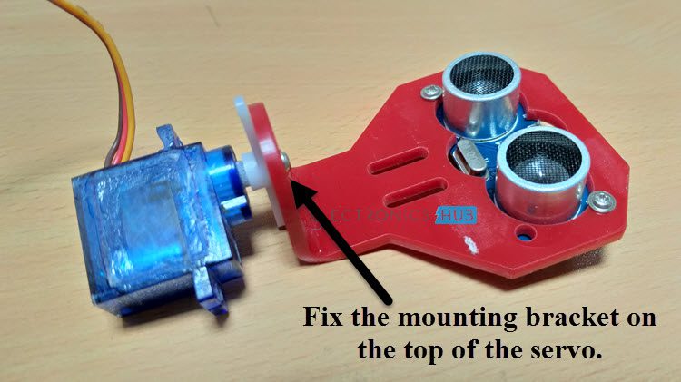
After making the connections, there is one important step in the construction you need to perform (not mandatory). Since the Ultrasonic Sensor must sweep an arc of 1800 (with the help of the Servo), I have used a mounting bracket as shown in the image below to fix the Ultrasonic Sensor.
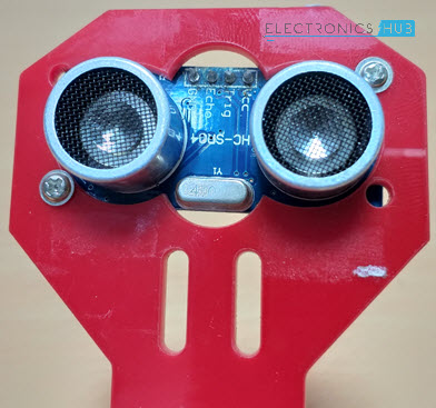
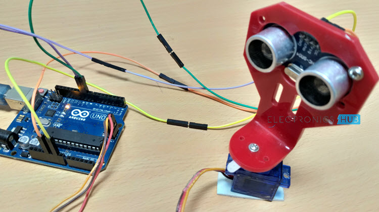
After fixing the sensor, the mounting bracket is screwed to the servo motor as shown below. As the bracket and the Ultrasonic Sensor adds weight to the servo, make sure to use a double-sided-tape to fix the Servo firmly to the surface.
This step is optional and you can make a simple structure with cardboard to hold the Ultrasonic Sensor firmly to the Servo.
A Reminder on Processing
If you are new to processing, it is a visual arts based software for learning to code. To download the application, visit the following link and choose your platform. Download Processing.
After downloading the Zip file (assuming the platform is 64-bit Windows), extract the contents of the zip file and you can find the processing application (.exe file).
The next step is to download a special library called “Toxi” from this link. After downloading the “toxiclibs-complete-0020” zip file, extract the contents to the folder of same name and move that folder to the Processing libraries directory (something like C:\Users\Ravi\Documents\Processing\libraries).
Code
There are two codes for this project: one for the Arduino UNO and the other for the Processing.
Arduino Code
The code for Arduino UNO is given below.
Processing Code
The code for Processing Application is given below.
Working
Initially, upload the code to Arduino after making the connections. You can observe the servo sweeping from 00 to 1800 and again back to 00. Since the Ultrasonic Sensor is mounted over the Servo, it will also participate in the sweeping action.
Now, open the processing application and paste the above given sketch. In the Processing Sketch, make necessary changes in the COM Port selection and replace it with the COM Port number to which your Arduino is connected to.
If you note the Processing Sketch, I have used the output display size as 1280×720 (assuming almost all computers now-a-days have a minimum resolution of 1366×768) and made calculation with respect to this resolution.
In the future, I will upload a new Processing sketch where you can enter the desired resolution (like 1920×1080) and all the calculations will be automatically adjusted to this resolution.
Now, run the sketch in the Processing and if everything goes well, a new Processing window opens up like the one shown below.
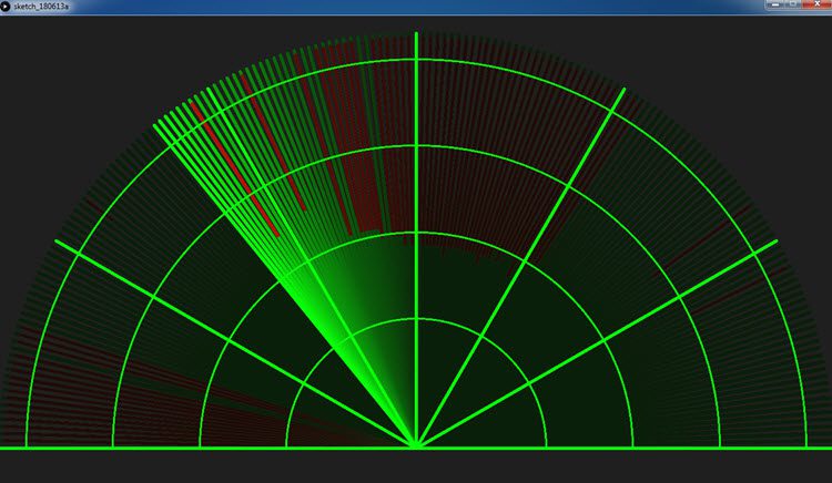
A Graphical representation of the data from the Ultrasonic Sensor is represented in a Radar type display. If the Ultrasonic Sensor detects any object within its range, the same will be displayed graphically on the screen.
The post Arduino Radar Project appeared first on Electronics Hub.
No comments:
Post a Comment