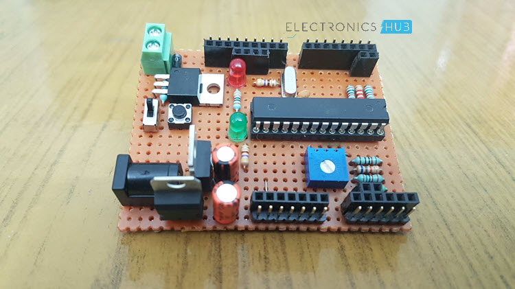
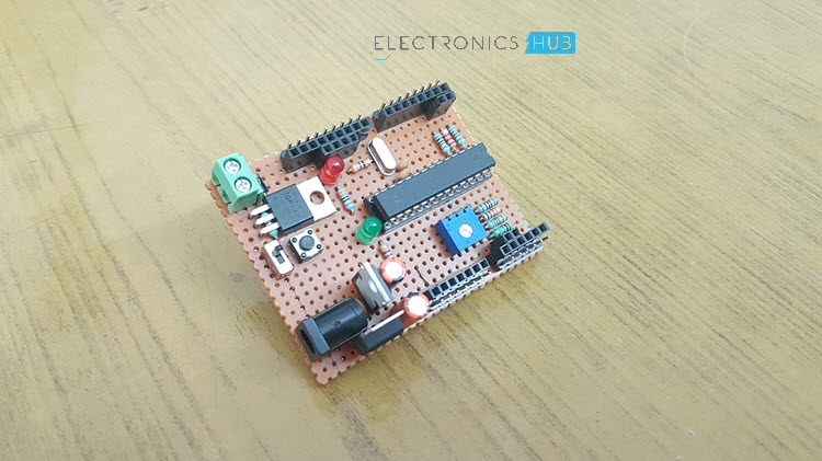
In this DIY Project, I will show you how to Make Your Own Arduino Board using easily available components and a very simple build process. Using this approach, you can make a custom Arduino Board that suits your needs.

Introduction
If you are following ElectronicsHub for some time, you will notice that we love Arduino. Not only it is a simple and easy to use platform, but also there is a huge community of users, developers that make frequent and significant contribution (either to hardware or software).
Using Arduino, you can implement simple LED Control Projects to complex Robots like these Bluetooth Controlled Robotic Arm and Line Follower Robot.
It is well and good as you can simple buy an Arduino board (an original one or a cloned one) and program it using the Arduino IDE. But what if you want to have a customized Microcontroller Board specifically for your project but still retain the important features of Arduino? Wouldn’t that be nice.
Well, in this project, I am going to show you how to Make Your Own Arduino Board by explaining the steps and process that I went through to build my custom Arduino Board.
Why Do You Need to Make Your Own Arduino Board?
Arduino Board (consider Arduino UNO as an example) provides a wide range of features like Digital Input / Output Pins, Analog Input Pins, PWM, Interrupts etc. out of the box. One of the main important features of Arduino is the USB Interface.
Simply connect your Arduino Board to the computer using an USB cable, open the Arduino IDE, write a simple code, upload it to Arduino. It is as simple as that.
But to interface with peripherals, say a Potentiometer or a Motor, you need to connect then using jumper wires.
If you some how want to integrate small components like POTs or Motor Drivers onto the Arduino Board itself to avoid the dangling wires, if would look nice and tidy and can help you go commercial (to sell your product).
The only way is to Make Your Own Arduino Board. Even if you are not building an embedded system around Arduino, you can still Make Your Own Arduino Board just for the sake of making it testing your custom design.

Prerequisites to Make Your Own Arduino Board
Before taking a look at the actual process of making your own Arduino Board, you need to keep a few things ready. The first important thing is the design of the board. If you have a custom design on mind, make use of any schematic capture software and start working on the design.
The second important thing is specific to this project. To reduce the complexity, I haven’t used the USB Connector with USB – to – Serial Convertor IC. Instead, I will be using the SPI Pins of ATmega328P (the microcontroller on Arduino UNO) to burn Bootloader, which is a one-time job, as well as upload a program.
So, take a look at this tutorial on How to Burn Bootloader to ATmega328, which gives a comprehensive information on burning Bootloader as well as the program.
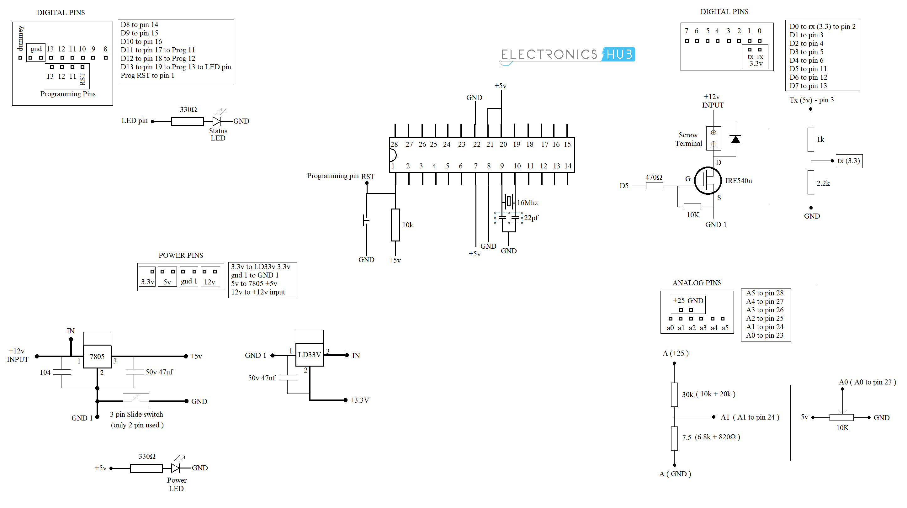
Circuit Diagram of Your Custom Arduino Board
As I have mentioned earlier, the first and important part to Make Your Own Arduino Board is to have a clear idea on the design of the board. This step starts with building the circuit. The following image shows the circuit of the Arduino Board in my project.

NOTE: To view a larger image, right click on the above image and click on “Open image in new tab” option.
Components
- ATmega328p Microcontroller IC
- 28 Pin IC Holder
- 16 MHz Quartz Crystal
- Capacitors – 2 x 22pF, 100nF, 2 x 47µF
- Resistors – 2 x 330Ω, 470Ω, 1KΩ, 2.2KΩ, 7.5KΩ, 2 x 10KΩ, 30KΩ
- LEDs x 2 (Red and Green)
- Push Button (for Reset)
- Slide Switch (ON / OFF)
- 5V Regulator (7805)
- 3.3V Regulator (LD33V)
- 10KΩ Potentiometer
- 1N4007 Diode
- IRF540N MOSFET
- Miscellaneous (Screw Terminal, Male Headers, Female Headers, 2.1mm Power Jack, Perf Board)
NOTE: These Components are specific to my design and your list of components may be different.
Make Your Own Arduino Board
If you are ready with the circuit diagram (double check every connection), you can proceed to Make Your Own Arduino Board. At this point, you can design the PCB Layout using any software and make your own PCB as shown in this tutorial: How to Make your Own PCB.
But to keep things simple, I have decided to go old school. Use a Zero Board and start building the board from scratch using loads of solder. I know this is not a reliable technique but I felt this is sufficient for a small tutorial.
May be in the future, I will design a semi-professional PCB and make a better-looking custom Arduino Board.
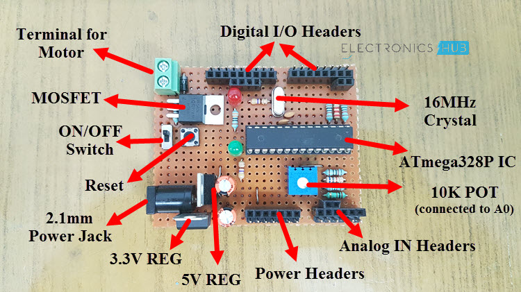
Important Features of My Custom Arduino Board
Now, I will point out some of the important features of my Arduino Board.

- I have included a MOSFET to drive a Motor and it is connected to D5 so that there is a chance of PWM Control as well.
- For Analog Input A0, I have connected a 10KΩ POT.
- Coming to Analog Input A1, I have connected a Potential Divider consisting of 30KΩ and 7.5KΩ Resistors to directly measure input voltage up to 25V.
- The TX and RX Pins are provided with an option of 3.3V Logic.
- There is slide switch to turn ON and OFF the Arduino Board.
- I have included two LEDs: One is a Power ON LED and the other is a User LED connected to D13.
- All the Analog and Digital (as well as the power) headers come with both Male and Female headers.
- A separate 4-pin female header for programming.
- In the power pins, I have provided options for 3.3V, 5V as well as 12V.
Conclusion
A DIY Project on How to Make Your Own Arduino Board is implemented here. Using a similar approach (and perhaps with a proper PCB) you can make your own Arduino Board to fulfil your custom project requirements.
The post Make Your Own Arduino Board – A DIY Tutorial appeared first on Electronics Hub.
No comments:
Post a Comment