Friday, 31 January 2020
New encapsulation technique protects electronic properties of sensitive materials
Wednesday, 29 January 2020
Making sense of flexible sensor systems
Nano-thin flexible touchscreens could be printed like newspaper
AC vs DC: The difference between alternating and direct current
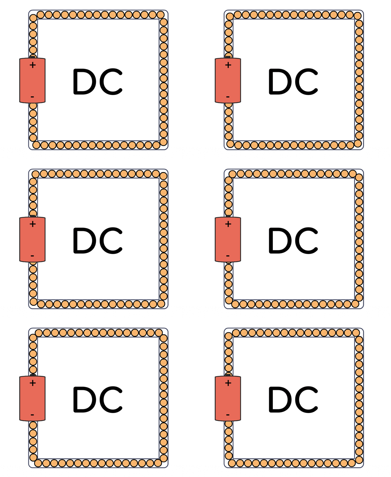
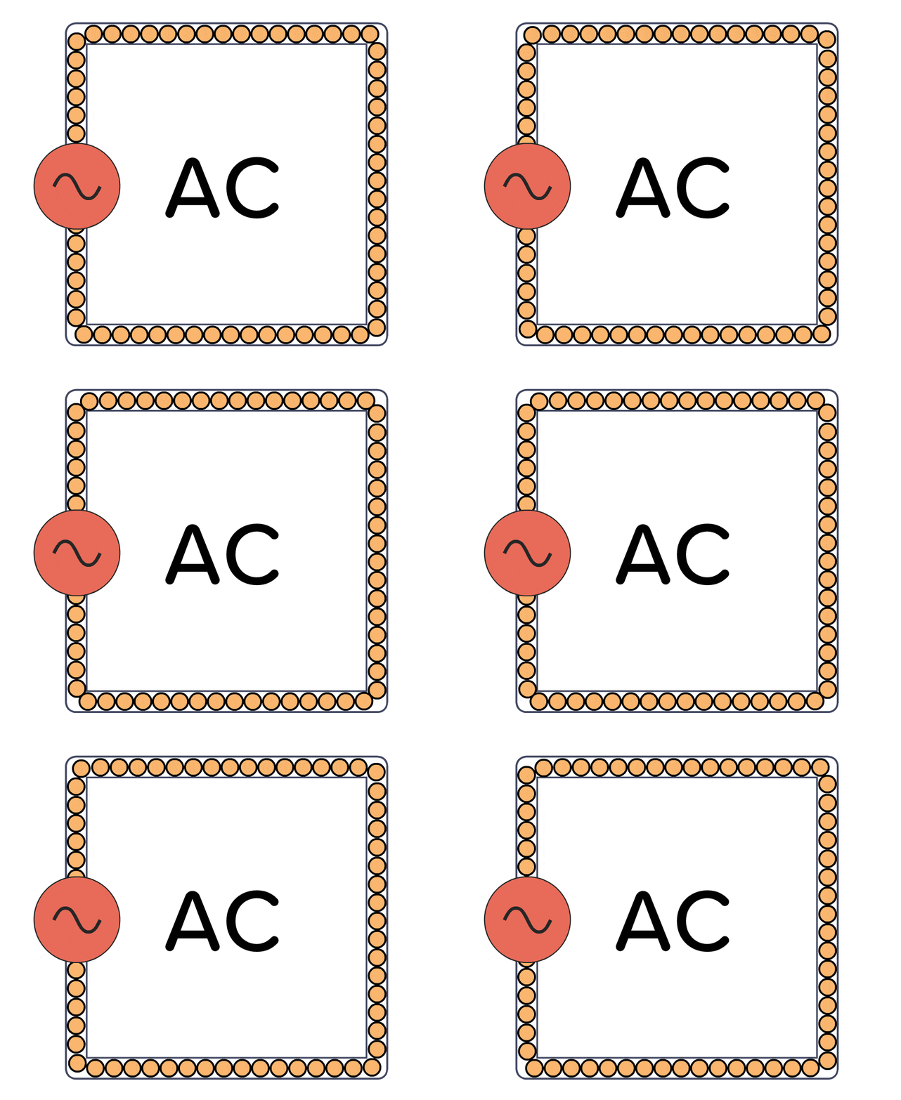
The difference between Alternating Current (AC) and Direct Current (DC) is simple. AC vs DC comes down to in which direction the current flows. AC is a current that alternates its direction. It goes back and forth continuously. DC is a current that flows in one direction.
Current flow in a DC circuit:

For example, a battery provides direct current. The current only flows one way out of a battery.
The current flow in an AC circuit:

In your wall sockets, you have AC. The current keeps changing direction about 50 to 60 times per second. But for many things, you have adapters that convert it into DC before it is used by a circuit.
(Although, it could as well have been DC in our walls if Edison had won the AC vs DC war back in the late 1800s against Tesla.)
AC vs DC in circuits
You usually need DC to power most things in electronics. I’ve never had the need for a power supply that outputs AC.
But you might find that you have AC in parts of your circuit. For example in audio circuits, radio circuits, or in power supplies.
The AC part is usually either a signal that represents something, like sound. Or an oscillating voltage to send a signal out into the field, like a radio transmitter.
Learn Electronics
If you’re looking to learn electronics, I recommend you focus on learning DC circuits. Knowing what AC is, is great to know. But most of the AC circuit lessons I’ve seen out there are focused on mathematical formulas – and don’t need it until you get to a more advanced level in electronics.
If you want to learn electronics from scratch, you’re invited to join us over at Ohmify. With more than 300 lessons to choose from and a friendly community of like-minded people to help you. And at the Ohmify forum, no question is too basic.
What are your biggest questions when it comes to AC vs DC? Let me know in the comments below.
Copyright Build Electronic Circuits
Monday, 27 January 2020
Method detects defects in 2D materials for future electronics, sensors
Sunday, 26 January 2020
New stretchable battery can power wearable electronics
Friday, 24 January 2020
Blue-emitting diode demonstrates limitations and promise of perovskite semiconductors
Thursday, 23 January 2020
Microchip capability expanded ewith new 3D inductor technology
Integrating micro chips for electronic skin
New material is heat-insulating and heat-conducting at the same time
Wednesday, 22 January 2020
Coating helps electronics stay cool by sweating
Designer-defect clamping of ferroelectric domain walls for more-stable nanoelectronics
Buckyballs can pave the way for molecular electronics
Thursday, 16 January 2020
Electron spins in slowly moving quantum dots may be controlled by electric fields
Simple VU-Meter Circuit
I put together this Voltage Unit (VU) meter using LEDs on a breadboard the other day. It only has 4 LEDs, but can easily be expanded to more:
It’s basically a simple display for showing a value. It’s originally for showing signal level in audio circuits, but there’s no reason you can’t use it to show temperature, rain intensity, light level, or whatever other value you are measuring.
In the video above, I added a potentiometer as a voltage divider between 9V and 0V, so that the output would be somewhere in between. This way I could easily test the VU meter.
If you want it to show audio level or any other signal with very low voltage, replace the potentiometer with an amplifier.
Here’s the circuit diagram:

The Qs are NPN transistors. I used BC547.
D1-D3 are standard diodes. I used 1N4007.
R1 to R4 are there to limit the current to the LEDs, and I used 1k.
R5 to R8 are there to limit the current through the transistors. I forgot what I used, but anywhere from 1k to 10k I think should work.
The potentiometer I connected between 9V and 0V. And the middle pin I connected to the “Input Voltage” port.
If you want this, but think there are too many components, an alternative is using the LM3914 IC.
Have you built this circuit or something similar? Let me know in the comments below!
Copyright Build Electronic Circuits
Wednesday, 15 January 2020
Toward safer disposal of printed circuit boards
Tuesday, 14 January 2020
Colloidal quantum dot laser diodes are just around the corner
Monday, 13 January 2020
Researchers solve a scientific mystery about evaporation
Friday, 10 January 2020
An 18-carat gold nugget made of plastic
Tuesday, 7 January 2020
New method gives robust transistors
Monday, 6 January 2020
Exploring the 'dark side' of a single-crystal complex oxide thin film
Thursday, 2 January 2020
End of year notes from Oyvind
So I just realized today that it’s not only a new year we are entering into…

We’re entering into a new decade!
I’ve been teaching electronics for about ten years now.
And it’s been a crazy ride:
From teaching a small group of students as a teaching assistant at the University – to reaching millions of people through my books, articles, videos, newsletter, workshops and online courses.
In 2019 I focused on reinventing Ohmify.
It used to be a collection of courses.
But the thing is that you don’t learn to build your own projects with electronics by watching some videos for a week.
You need to build several projects. You need to fail. You need to learn more. Fail more. Ask for help. Then succeed. Then try something harder.
And you never “finish”.
It’s like learning to draw. Or to play the guitar. You might learn to play a song in a day. But there’s always more to learn. You can always get better. You can always learn new songs, new techniques.
So I reinvented Ohmify to support you do this.
I developed more learning material. And I experienced with different formats:
Like weekly online workshops that I developed week-by-week. And draft lessons I published after the first draft to get feedback and questions.
All based on what you were asking for.
But the biggest change I did was to set up a community forum…
Everyone needs to learn the same fundamentals to get a basic understanding of electronics. But after that, there are hundreds of paths to take!
Maybe you have a specific goal of lighting up some LEDs with a remote-control?
Maybe you want to custom-fit electromotors on your child’s Brio train to make it remote-controlled?
Or maybe you’re more interested in learning all the ins and outs of sensors to create your own custom weather station?
In the forum, everyone can get individual help with their own unique path.
And not just from me.
It’s the members that really make up the community.
As we’re entering a new decade, I have no idea what the next ten years have in store for me…
But I’ll continue to develop Ohmify and help our members.
Probably launch a few crazy projects along the way.
And welcome whatever else the universe has in store for me.
Happy New Year to you!
Keep On Soldering!
Oyvind @ build-electronic-circuits.com
Copyright Build Electronic Circuits
Researchers develop recyclable, healable electronics
Electronics often get thrown away after use because recycling them requires extensive work for little payoff. Researchers have now found a w...
-
Do you need a MOSFET gate resistor? What value should it be? And should it go before or after the pulldown resistor? If you’re a bit impati...
-
I was first introduced to logic gates when I was around 14 years old. I had heard that computers consisted of ones and zeroes. But I didn’t...
-
CMOS (Complementary Metal Oxide Semiconductor) The main advantage of CMOS over NMOS and BIPOLAR technology is the much smaller power dis...