This Arduino button circuit is a simple example that shows you how to connect buttons to an Arduino.
In this quickstart guide, you’ll learn how to connect a button to an Arduino board and read a HIGH or LOW depending if the button has been pushed or not. You’ll use the Light-Emitting Diode (LED) that is included on the board to turn on and off with the button so that you can verify that your button press code is working properly.
This is a great practice circuit to build as you’re learning Arduino. The code is straightforward and the connections are simple.
Parts Needed
- Arduino Uno
- Breadboard (and some breadboard wires)
- Resistor 10 kΩ
- Pushbutton or Switch
- Wires
Arduino Button Circuit
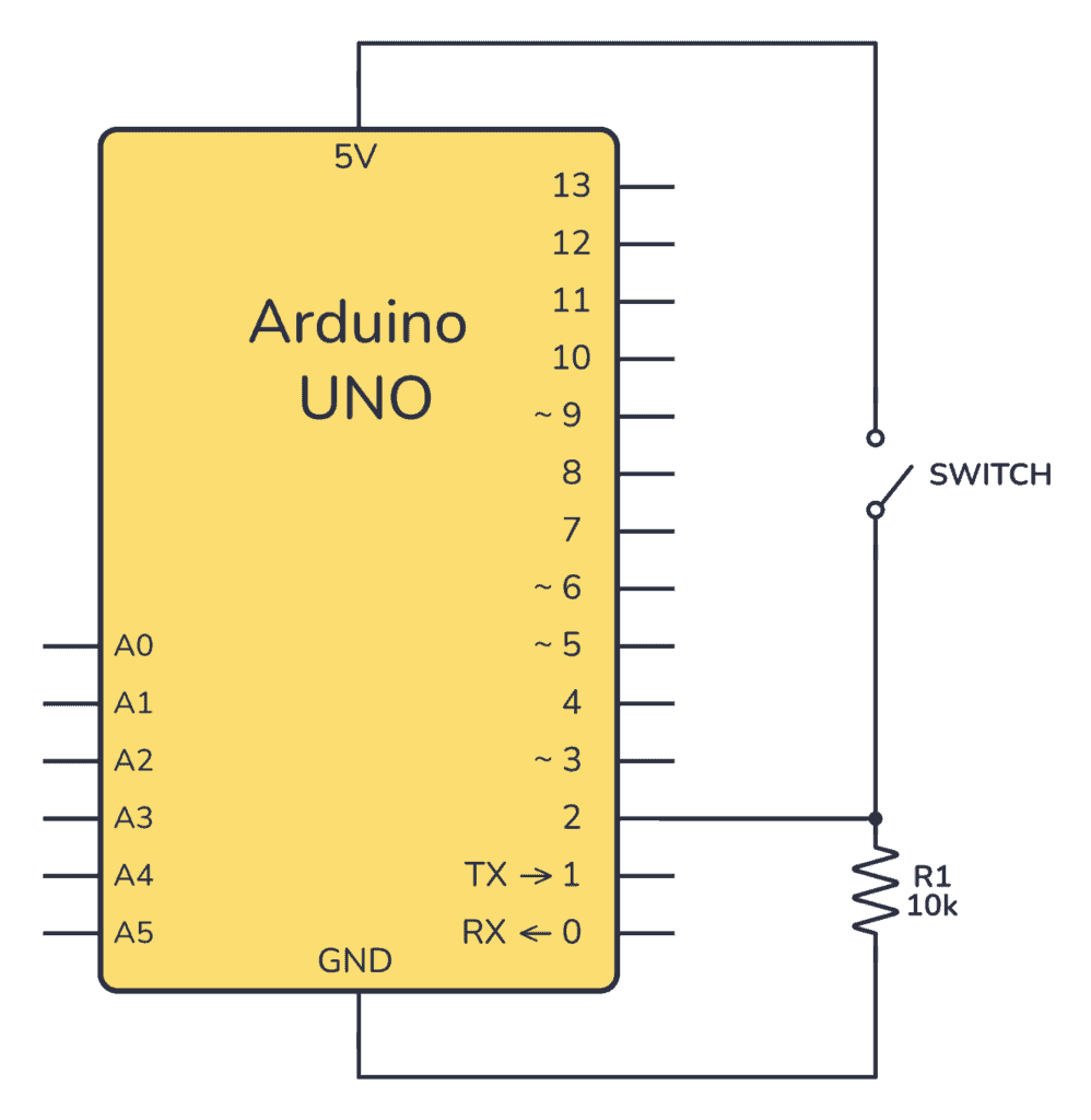
To connect a button to an Arduino, you’ll need a pull-down or a pull-up resistor. This is to make sure that when the button is not pushed, it has a defined value. In this example, we’re using a pull-down resistor of 10 kΩ.
Connecting On a Breadboard
Here’s how you can connect a potentiometer to an Arduino by using a breadboard and some cables:
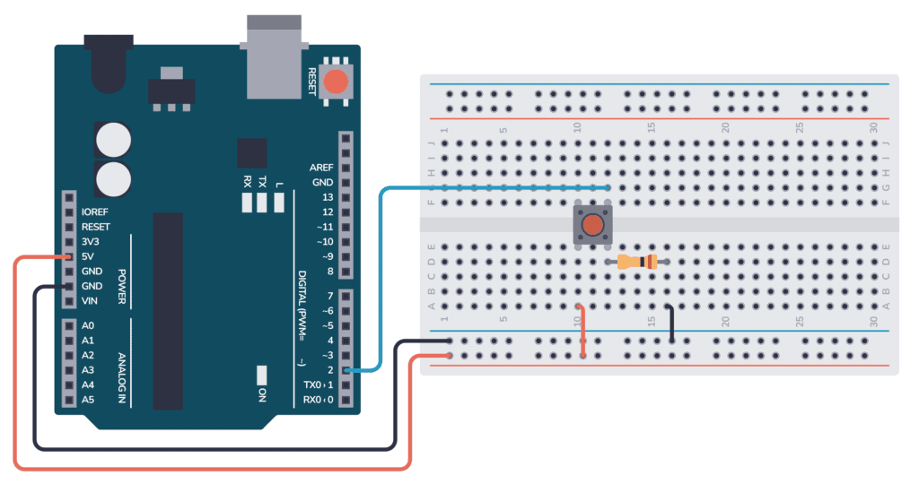
Connect one side of the pushbutton to the 5V pin on the Arduino. And connect the other side to the digital input D2 on the Arduino. Connect a resistor from D2 (and the button) to ground.
Arduino Button Code
The following code reads the button state, then turns the onboard LED either on or off, based on if the button was pushed or not.
As with all Arduino code, the code is structured around the two main functions setup() and loop():
- Inside setup(), you need to set what pins should be inputs and outputs.
- Inside loop(), you need to read the button input and set the LED pin based on the button state.
Check out the complete code:
const int buttonPin = 2;  // the number of the pushbutton pin
const int ledPin = 13;    // the number of the LED pin

// variables will change:
int buttonState = 0;  // variable for reading the pushbutton status

void setup() {
  // initialize the LED pin as an output:
  pinMode(ledPin, OUTPUT);
  // initialize the pushbutton pin as an input:
  pinMode(buttonPin, INPUT);
}

void loop() {
  // read the state of the pushbutton value:
  buttonState = digitalRead(buttonPin);

  // check if the pushbutton is pressed. If it is, the buttonState is HIGH:
  if (buttonState == HIGH) {
    // turn LED on:
    digitalWrite(ledPin, HIGH);
  } else {
    // turn LED off:
    digitalWrite(ledPin, LOW);
  }
}
How the Code Works
Here’s an overview of how the code works:
- Variables & Constants:
buttonPin: Pin 2 where the button is connected.ledPin: Pin 13 where the LED is connected.buttonState: Stores the status (HIGH or LOW) of the pushbutton.
setup():- Sets
ledPinto OUTPUT andbuttonPinto INPUT.
- Sets
loop():- Reads the pushbutton’s state.
- If button is pressed (HIGH), the LED turns on.
- Else, the LED turns off.
So in this code, pressing the button on pin 2 toggles the LED on pin 13.
Copyright Build Electronic Circuits


No comments:
Post a Comment