Friday, 12 October 2018
Researchers quickly harvest 2-D materials, bringing them closer to commercialization

Thursday, 11 October 2018
Arduino based Smartphone Charging Controller
In this project, I will show a very practical project called Arduino based Smartphone Charging Controller, where the amount of the time your smartphone charges its battery is controlled by you.
Introduction
Almost every mobile phone (either a fancy smartphone or a simple feature phone) user faces this one issue: connecting your phone to the charging adapter and forgetting that you plugged in the device.
Almost all the modern charge controllers on mobile phones are very advanced and detect when your battery is fully charged and disconnect supply of power to the battery (not completely but a keeps the device in a charging state known as trickle charge).
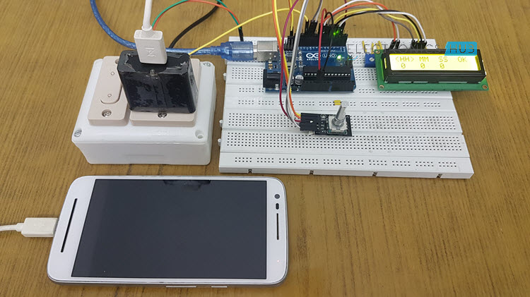
But the main disadvantage of keeping the device plugged in even after the battery is full is its affect on the lifetime of the battery. Every battery has a limit to the number of times it can be charged (known as charge cycles).
Also, temperature plays an important role in the life of a battery. Higher temperatures might disrupt the chemistry of the battery.
But what if I told you that the Arduino based Smartphone Charging Controller project can be help full to control the charging time and once the time is up, the power to the charging adapter is disconnected. Sounds interesting and practical, right.
So, let’s get started with the project Arduino based Smartphone Charging Controller.
Concept behind Arduino based Smartphone Charging Controller
The main concept behind the Arduino based Smartphone Charging Controller is very simple. Set the time for which you wish to charge your mobile phone. Once the time is reached, turn off the power supply to the charger.
For example, you have set the charging time as 2 hours (maybe based on the previous observation or by mathematical calculations). The power to the charger is turned on with the help of a relay and the timer begins.
Your mobile phone gets charged for the next two hours and when the countdown is reached to the 2-hour mark, the relay is turned off and as a result, the power supply to the charger is also cutoff.
Circuit Diagram
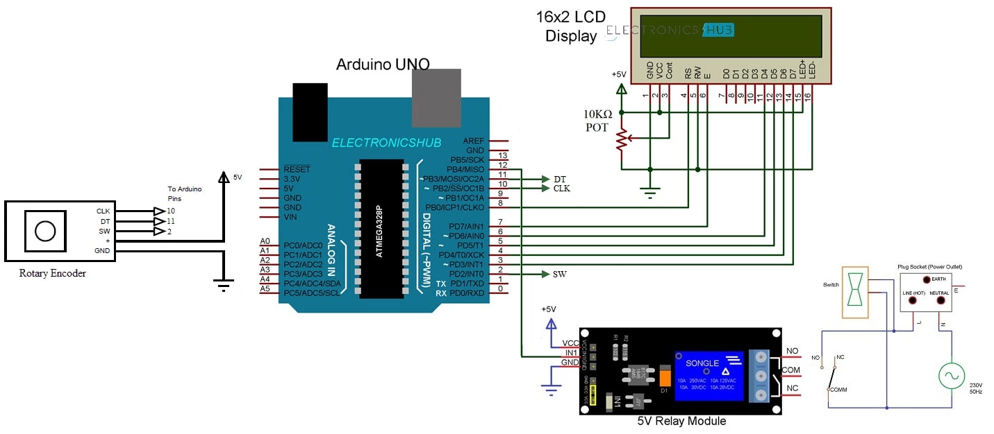
The following image shows the circuit diagram of the Arduino based Smartphone Charging Controller system.
Components Required
- Arduino UNO
- 16×2 LCD Display
- Rotary Encoder
- 5V Relay Module
- 10KΩ POT
- Connecting Wires
- Breadboard
- Charging Adapter
- Single Socket Power Outlet Box
NOTE: There is a separate tutorial on using Rotary Encoders with Arduino called “Rotary Encoder With Arduino – Know it all”. You may refer to that tutorial for any information regarding rotary encoder.
Circuit Design
The main components of the project other than Arduino UNO are Rotary Encoder, Relay and 16X2 LCD Display. Let me start with the Relay. Connect the IN1 Pin of the Relay Module to Pin 12 of Arduino.
Coming to the rotary encoder, its CLK, DT and SW pins are connected to Pins 10, 11 and 2 of Arduino UNO. Finally, the LCD, Pins 8 through 3 of Arduino are connected to RS, E, D4 – D7 of the LCD.
Setting up the Arduino based Smartphone Charging Controller Project
Components like 16×2 LCD Display, Rotary Encoder and Arduino UNO can be placed on a breadboard but I though it would be nice to place the relay in a single socket power outlet box with a control switch so that the relay would control the socket and you can plug in your charging adapter into the socket.
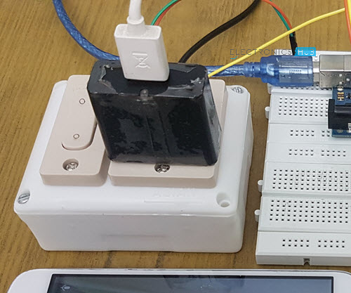
WARNING: If you are implementing this project, you have to deal with 230V AC Mains Supply, which is potentially dangerous. I suggest you take an expert guidance for the connections.
Code
The code for the project Arduino based Smartphone Charging Controller is given below.
Working
After making the necessary connections as per the circuit diagram, upload the code to Arduino and turn on the power supply.
You will get Hours (HH), Minutes (MM), Seconds (SS) on the 16×2 LCD Display. By selecting Hours, rotate the knob on the rotary encoder to set the desired number of hours. When the hours value is set, push the knob to fix that value.
Similarly, you can set minutes and seconds. After everything is set, select OK on the LCD and push the knob.
Now, the relay gets activated (which means the phone starts charging) and the countdown begins for the amount of time set by you. Once the countdown reaches “0”, the relay is turned off (power to adapter is off).
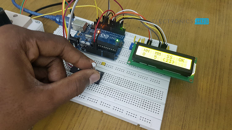
During charging if there is a power failure, the remaining time is stored in the memory and when the power comes back, it will prompt you whether to continue with the countdown or to set a new time. Accordingly, the charging will be performed.
Conclusion
Arduino based Smartphone Charging Controller is implemented here which a simple project for controlling the amount of time you charge your mobile phone.
Using this project, you can plug in your phone to the charger, set the time for which your phone gets charged and forget as the project will automatically disconnect power to the charger.
This project is very useful for people who tend to charge the phone during night time or those who often forget that they plugged in the phone to the charger.
The post Arduino based Smartphone Charging Controller appeared first on Electronics Hub.
How to build a kitchen timer?
 I’m building a kitchen timer these days.
One of those things you can set to for example 8 minutes so that it beeps when your pasta is finished.
You need:
* a display to show the time
* some buttons to set the time and start/stop the timer
* a buzzer to create sound when the timer finished
* a microcontroller to control the display, detect button press, and keep track of time
Since we only need numbers, a good type of display to use is a 7-segment LED display.
It’s easy to control, and usually pretty cheap.
The buttons can be standard tactile pushbuttons.
And an active buzzer makes the sound turn on with just a high output from the microcontroller.
The microcontroller could be an Arduino if you want to keep it simple:
https://www.build-electronic-circuits.com/what-is-arduino/
But if you want to make it compact, better to design your own microcontroller board:
https://www.build-electronic-circuits.com/microcontroller-tutorial-part1/
The components are not expensive.
Maybe around $10 in total.
You can learn all the skills you need in order to build one in Ohmify:
https://ohmify.com/join/
Soon there will also be a course that takes you through it step-by-step.
Keep On Soldering!
Oyvind @ build-electronic-circuits.com
Copyright Build Electronic Circuits
Wednesday, 10 October 2018
Researchers develop 3D printed objects that can track and store how they are used
Research on light-matter interaction could improve electronic and optoelectronic devices
New NIST method measures 3D polymer processing precisely
Topology, symmetry and magnetism: Heusler, Weyl and Berry
-
Bluetooth Controlled Electronic Home Appliances is a simple project, where we can control different electrical appliances and electronic de...
-
In this project, we will learn about TP4056 Lithium Ion Battery Charger which is based on the TP4056 Li-Ion Battery Charger IC. In the proce...
-
In this project, you will build a touch sensor circuit. It’s a cool and simple circuit that allows you to control an LED with the touch of a...


