In this project, you will build a touch sensor circuit. It’s a cool and simple circuit that allows you to control an LED with the touch of a finger. And you only need three components, how cool right?
You can build this circuit if you’re a total beginner.
The Touch Sensor Circuit Diagram
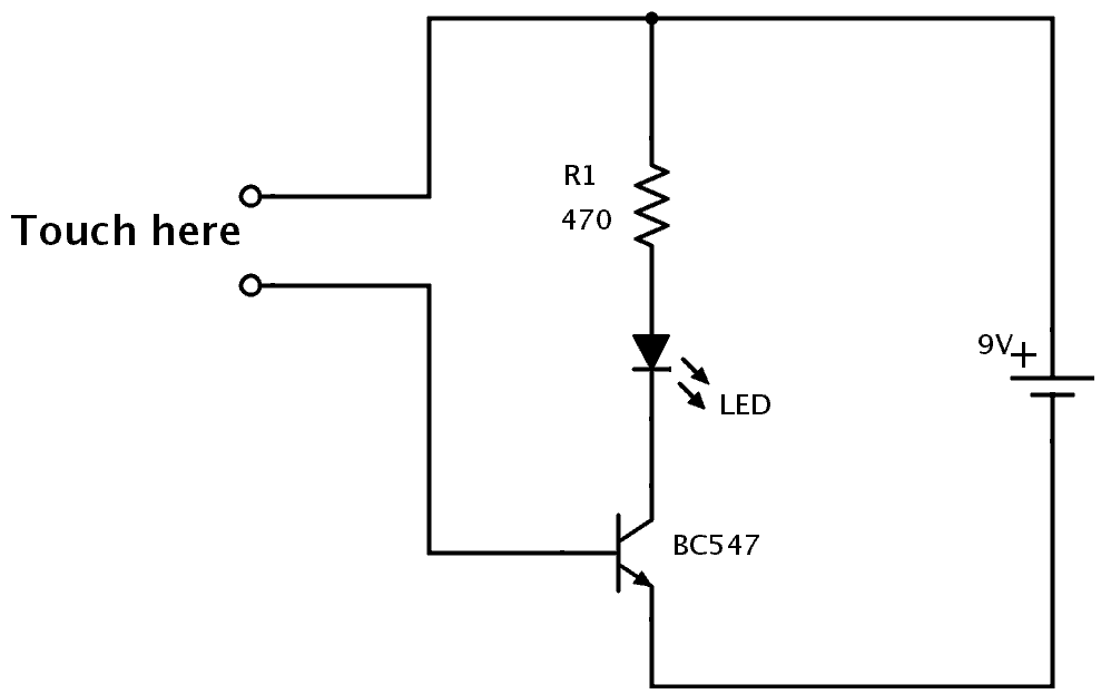
You only need a resistor, a transistor, and an LED to build this project. Below you’ll find the schematics for the touch sensor circuit:
Components Needed
- 9V Battery
- 9V Battery Clip
- Breadboard
- Jumper Wires
- 470Ω Resistor
- Red LED
- NPN Transistor (BC546/547/548 or similar)
These are all standard components you can find at most electronics shops.
How It Works
Your body has electric resistance. You can check by measuring the resistance between your fingers with a multimeter.
So when you touch the wires of the touchpad, your body behaves as a resistor. This means a small amount of current can flow from the plus of the battery, through the transistor’s base, and turn on the transistor.
When the transistor is on, current can flow from collector to emitter of the transistor and the LED will turn on. Learn more about this in the article on how transistors work.
How to Build the Touch Sensor Circuit
You will build this circuit on a breadboard. But once you’ve tested that it works properly, feel free to go a step further and solder it.
Step 1: Connect The Transistor
Start by connecting the transistor a little bit down on the board.
If you’re using a BC546/BC547/BC548 transistor, you can connect it as shown in the figure. The collector goes into row 10, the base in row 11, and the emitter in row 12.
Note: If you have a different transistor model (ex the 2N3904), you need to check the datasheet to find out which leg is which, and adjust your connections accordingly.
Step 2: Connect The Resistor
Next, connect the resistor. Connect it from row 1 to row 9.
Notice that it is not connected to the transistor since the transistor is connected in row 10.
(In the following images, a 220 Ω resistor is shown. But it could be a good idea to use a larger value like a 470 Ω resistor to make sure your LED can handle the current.)
Step 3: Place The LED And Touchpad
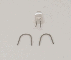
Now, you’re going to connect the LED and the touch-sensing part. For the touch-sensing part, you’ll need two exposed wires. You can get this from the LED. The LED has much longer legs than needed.
Cut off the legs of the LED so that only around 1 cm / 0.4 in is left on the LED. Bend the two legs that you just cut off, as shown below, so that they fit in between four columns on a row.
Place one on row 4 between column A and D. And one on row 6 between column A and D. This leaves room for a jumper wire to be connected later.
Insert the LED with its positive side on row 9 column F, and the other side on row 10 column F. Now the LED is connected between the resistor and the collector of the transistor, just like in the schematics of this circuit.
Step 4: Connect The Touchpad
Now you need to connect the two touch wires to the correct points in the circuit, using jumper wires.
Connect one jumper wire from row 1 column F to row 4 column E. And one jumper wire from row 6 column E to row 11 column I.
Step 5: Touch It!
Next, connect a jumper wire from row 1 column J to the positive supply column on the right. Then connect a jumper wire from row 12 column I to the negative supply column on the right.
Connect your battery connector and plug in the battery.
If everything is connected properly, nothing should happen right now.
But then, try to touch the touch wires so that your finger touches both wires at the same time, and the light will turn on.
If you can’t see the light, try making the tip of your finger wet before touching again. When the skin of your finger is wet, the resistance decreases so that more current can flow through your finger and to the base of the transistor.
What If There Is No Light?
In this circuit there are three common errors:
- the orientation of the LED is wrong
- the orientation of the transistor is wrong
- you are using a PNP transistor instead of an NPN transistor
- your finger is too dry
The NPN and the PNP transistors look exactly the same, so the only way to distinguish them is to look at what is written on the transistor. If it says BC557, it’s a PNP transistor, which is *not* correct. If it says BC546 (or BC547 or BC548) it’s NPN and it’s correct.
If you tried all of the above and it’s still not working, check the resistance value of your resistor. It should be 470 Ω. If it’s much more, it restricts the current to the LED too much. If it’s much less, it might have broken the LED.
If you have any questions about this experiment, use the comment field below.
The Result
In the video below you can see the process of building this, and the final result showing the working circuit:
Copyright Build Electronic Circuits


No comments:
Post a Comment