In this tutorial, you’ll learn how to build a 555 police siren circuit using two 555 timer ICs.
The 555 timer is a popular integrated circuit (IC) for hobbyists and can be used for a great variety of projects. For this project, we are going to use it to create sound with a twist!
Instead of a “straight” sound, we are going to make the frequency change automatically so it ends up sounding like a wailing police siren.
The 555 Police Siren Circuit
Below you’ll find the schematic for this circuit.
At first sight, the circuit might seem big and complicated. But if you take a closer look, you can see that the circuit is formed by three different basic circuits that we’ll go over in this article.

This project consists of the following three circuits combined:
- Red square: Slow 555 circuit in astable mode
- Yellow square: PNP switching circuit with a turn-on delay
- Blue square: Fast 555 circuit in astable mode with a speaker and using CV to modify the frequency
Components Needed
- 555 Timer IC x2
- PNP Transistor (PN2907)
- Small Signal Diode (1N4148)
- 8 Ω Loudspeaker
- 100k Ohm Resistor x3
- 10 kΩ Resistor x4
- 1 kΩ Resistor
- 100 Ω Resistor
- 100 µF Electrolytic Capacitor
- 10 µF Electrolytic Capacitor
- 100 nF Non-Polarized Capacitor
These are standard components you can find at most electronics shops.
How it Works
As you can see in the schematic, the circuit has three different parts for it to work. First, we have the astable multivibrator, which outputs an oscillating signal similar to this:
This is a very common configuration for 555 timers, and in this case, it’s configured to oscillate somewhat slow.
The second circuit is a PNP transistor switching circuit with a capacitor connected to its base. The capacitor will make a softer transition between 1 (max voltage) and 0 (GND). The output of this circuit will be a voltage going up and down and is connected to the CV pin of the third circuit.
The third circuit is almost the same as the first circuit, except for a couple of changes. First, it uses a much smaller capacitor, which will make the circuit reach higher frequencies. And second, it takes a varying voltage input on the CV (control voltage) pin. The output frequency will vary a bit up and down as this voltage goes up and down.
The result of this is a frequency that is going up and down, just like a police siren.
Building the Circuit
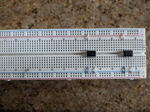
To build the 555 police siren circuit we are going to use a breadboard. First, connect every direct connection between the ICs, VCC, and GND.
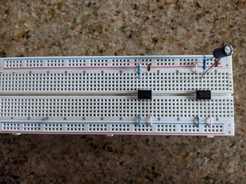
Then add the components that are connected between the IC, VCC, and GND. Remember to not cover all the holes in the row so you can add more connections later if necessary.
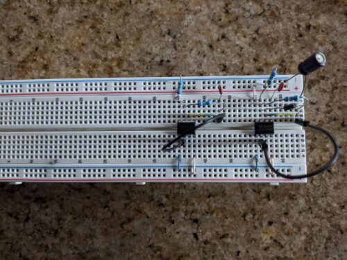
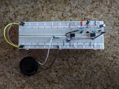
Then add the rest of the components and wires that make up the IC circuits. You can see that I used a small jumper (the yellow with blue cable) to take pin 6 to another row so that the components are placed more comfortably.
After this, connect the components for the switching circuit.
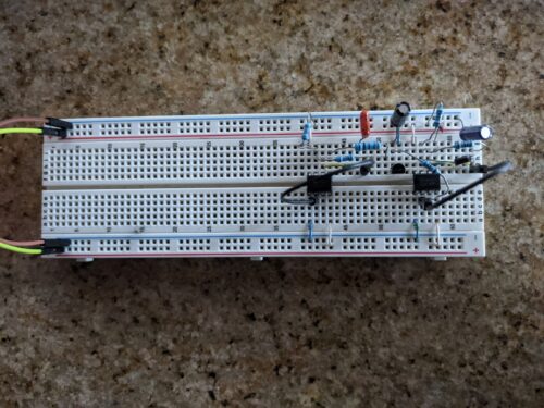
And then, add the speaker.
Remember that for every connection you can use any kind of jumper wire. I used small copper wires on occasions to avoid cluttering my circuit with a lot of oversized cables.
The Finished 555 Police Siren Circuit
For this project, I recommend trying different values for the capacitors that control the 555 circuits, and the base of the transistor. Each capacitor will affect the sound in different ways: C2 will affect the oscillation of the sound, C3 is going to affect the curve in which the sound changes, and C4 will change the range of the pitch in which the siren is going back and forward.
If you take C3 out of the board completely, you will notice how the sound changes in an abrupt manner, since there is no capacitor softening the frequency change.
Be careful with C2, since having a very low capacitor may change the oscillation into just a straight sound, on the contrary, a too high capacitor will make the changes too slow. In the video displayed above, the capacitors are different from the ones in the schematic, so you will hear a slightly different sound in your project.
Copyright Build Electronic Circuits

Hi , this was a nice informative & interesting Article. thank you for sharing this Article. I have seen more interesting related to projects like Matlab Based Projects for ECE at Takeoff Projects.
ReplyDelete